August 20, 2006

Structural Member Wizard

You may already be familiar with the Structural Member Catalog, a handy feature that has been available in Autodesk Architectural Desktop since at least the 3.3 release. The Structural Member Catalog provides an easy way to create Structural Member Styles based on real-world structural members. [Images here are from the 2006 release.]


But perhaps you have a need for a structural member style that is not in the catalog, whether to use it as a “generic” member, until the actual member is determined and you prefer not to use a real-world shape to make it easy to distinguish later; you have a special size not in the catalog; or you have some other need for a shape not in the catalog. For example, a while back, Brad Crouse had posted in the AUGI Forums [see this thread and this thread] that he was trying to create model in ADT at 1/16 actual size, in order to show, at full size, the “toy” buildings he intends to build.

One option would be to create custom structural member shapes, by drawing each outline as a closed polyline, and then using the -AecsMemberShape command to create the shapes. But if the shapes you need match “standard” structural shapes, with non-statndard size parameters, you may be able to save yourself some time and effort by using the Structural Member Wizard. You can access the Wizard from the pulldown menus, Format > Structural Members > Wizard…, or by invoking the _AecsMemberStyleWizard command.


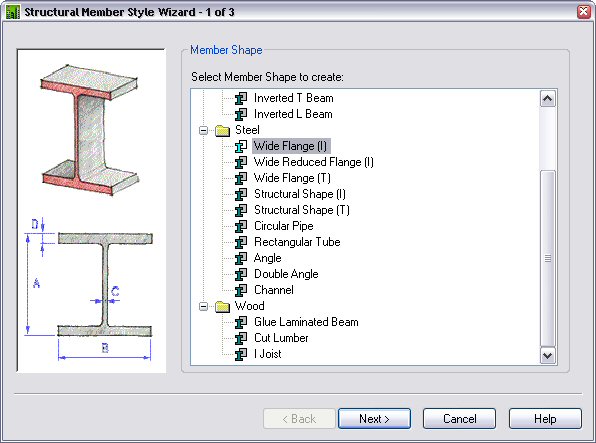
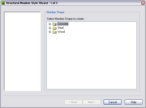
The Structural Member Wizard is a handy, dialog-driven utility that prompts you for the appropriate dimensional parameters for various types of concrete, steel or wood shapes, then generates a Structural Member Shape and Style for you to use. You can see the available options in the images below for concrete…

…steel…

…and wood.


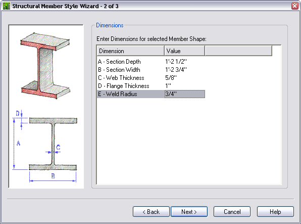
Let’s assume that our project is in the Schematic Design Phase, and we have managed to get the structural engineers to commit to using W14’s for the columns. We do not know the exact size for any of the columns, but the engineers have allowed that the largest column would be a W14x99. For schematic purposes, we want to make certain that our column enclosures can handle both the widest and deepest section, so we will use the Structural Member Wizard to create a “composite” structural member that combines the flange width of the W14x99, 14.656”, with the depth of the the W14x82, 14.31”, rounded up in case the final calculations sneak in a larger member or two. Our schematic column will have the following parameters:

A – Depth: 14.5
B – Flange Width: 14.75
C – Web Thickness: 0.625
D – Flange Thickness: 1.00
E – Weld Radius: 0.75

Start up the Structural Member Wizard and choose the Steel Wide Flange (I) option on “page” 1 of 3.

Select Next > to move to page 2 of 3, and enter the data noted above.

Select Next > and enter a style name, like “W14-Schematic” on page 3 of 3, then select Finish.


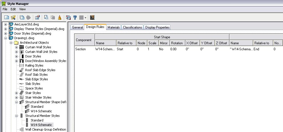
The Wizard then creates both a Structural Member Shape Definition and a Structural Member Style called “W14-Schematic”, ready for you to use.

Comic Relief

For those of you out there in the architectural profession who may be taking your job just a little too seriously, this site may help rebalance your outlook. At the very least, you may get a chuckle or two.

Thanks go out to Bryan L. Myers, in the AUGI ADT/ABS "Watering Hole" Forum for the link, in the "What they don't teach you in Architecture School" thread.

August 13, 2006

ADT Schedule Feature Resources

Here are some links to various resources that can help you understand the Scheduling Feature of ADT/ACD-A. Some are from some time back, so the specifics for more current releases may be slightly different, but all have something to offer. Do not forget to check out the ADT/ACD-A Help, too.

Brain Dumps 13, Schedule Basics and 15, Creating Schedule Tags, by Matt Dillon
Grab these from Chris Yanchar's Between the Walls ADT Weblog
or go to the original threads that were the basis of the Brain Dumps:
Brain Dump 13, Schedule Basics
Brain Dump 15, Creating Schedule Tags
9/1/2008 Update: The links to the Brain Dumps in Chris' blog appear to be dead, so you will have to go to the original threads.

Brain Dump 13, Schedule Basics, updated for ADT 2006
This is an update of Matt Dillon's classic, based on ADT 2006 means and methods.

Property Data Enhancements, by Scott Arvin
This "must read" covers the "new" property types that were added in ADT 2004, including formula properties.

NOTE: AUGI now has "levels" of membership, and access to the AUGI Training Program (ATP) materials is not part of the free membership level. In order to have access to the ATP materials noted below, you will have to join at one of the paid levels.

ATP071 Schedule Basics Course Materials, by David Koch
If you are a member of AUGI [its free], you have access to archived AUGI Training Program course materials. Download the materials for ATP071, which can be found by logging into the AUGI website and, from the Home page, clicking on the following links:
Education > AUGI Training Program > Archived ATP Courses
Scroll down to April, 2005 and download the course materials for ATP071. Then visit the archived Course Forum [click on the link] and look for the "Formula Property Exercise" thread. Download the supplemental exercise on formula properties that is attached to my first post in that thread.

Not an AUGI member yet? Sign up here.

ATP121 ADT Formula Properties Course Materials, by David Koch
This course was offered in June, 2006, and is also available in the ATP Archives.

Autodesk University 2007 - AB114-4 Get Fully Equipped in AutoCAD® Architecture Session Materials
Details on how to access the session handout and sample files can be found in this blog article.

Here are some previous articles in my blog, related to the Schedule Feature, that you may have missed:
11/25/2004 - Autodesk Architectural Desktop Tags
12/21/2004 - Overriding A Property Value Using A Formula
12/22/2004 - Clustering Spaces Within a Unit in a Space Schedule
12/24/2004 - Electrical Device Schedule Using Clustering
01/12/2005 - "Unformatted" Properties for Formulas
01/29/2005 - VBScript Operators for Formula Properties
03/21/2005 - ADT 2006 Tags Illustrated
04/03/2005 - Formula Property Interface Improved in ADT 2006
04/19/2005 - Scale-Dependent Tags in ADT
07/03/2005 - Structure/Flow in Formula Properties: If/Then/ElseIf/Else Construct
07/04/2005 - Multi-Line Room Name Formula Improvements
07/09/2005 - Multi-Line Room Name Formula Revisited
07/09/2005 - Structure/Flow in Formula Properties: Select Case Construct
07/16/2005 - Unformatted Properties and Numeric Precision
07/16/2005 - WxH Formula For Windows
08/03/2005 - Schedule Column Loss in "Old" Drawings
08/31/2005 - Rounding Up Property Data Values
08/31/2005 - Rounding Revisited
09/03/2005 - Rounding Redux
09/15/2005 - Rounding to Death
09/24/2005 - Scale-Dependent Tag Tools in ADT 2006
11/02/2005 - Filtering Objects in an ADT Schedule
11/14/2005 - Dealing with NA in Formulas
12/13/2005 - Sorting Schedules by Door Numbers with Suffixes
12/20/2005 - Underline in Tag But Not in Schedule
12/24/2005 - Schedule Table Placeholders
12/28/2005 - Schedule Basics Brain Dump for 2006
01/04/2006 - Residential Door Tags
01/12/2006 - Sorting Character Strings Like Numbers
01/14/2006 - Sorting Character Strings Like Numbers Image
01/14/2006 - Richard Binning: Auto Tagging With VBA
01/15/2006 - Door/Window Assembly Frame Depth in Window Schedule
01/25/2006 - Using System Variable Values in Formula Properties
01/28/2006 - Formatting Areas and Volumes in Schedules Using Drawing Setup
02/03/2006 - Underline in Tag But Not in Schedule II
03/11/2006 - Enhanced Property Data Features in ADT 2007, Part 1 [visibility and order]
03/21/2006 - Enhanced Property Data Features in ADT 2007, Part 2 [anchor and graphic properties]
03/24/2006 - Enhanced Property Data Features in ADT 2007, Part 3 [unit type]
03/31/2006 - Enhanced Property Data Features in ADT 2007, Part 4 [list definition]
04/08/2006 - Enhanced Property Data Features in ADT 2007, Part 5 [table title and header overrides; formula columns]
04/27/2006 - Stacking Properties in a Schedule Table
05/01/2006 - Using Property Data Formats to Force Real Number Interpretation
05/04/2006 - Retrieving the Door Type of a Door Style
05/23/2006 - Retrieving the Door Type of a Door Style 2
06/10/2006 - Tag for Polyline-based "Rooms"
06/17/2006 - Separating Structural Shape Names in a Complex Structural Member Style
06/24/2006 - Automatically Displaying a Viewport’s Scale
07/29/2006 - Room Name/Number PSD Heads Up in 2007
09/03/2006 - NA in Formulas Revisited
09/09/2006 - List Definitions and Multi-Line Room Names
01/09/2007 - Formula Property VBScript Help
01/10/2007 - List Definitions - Utility to Import/Export
01/20/2007 - Scale-Dependent Schedule Tags in ADT 2006 or 2007
02/16/2007 - Dealing "*Xxx not found*" Location Property Result
03/03/2007 - Adding a New Scale to a Scale-Dependent Block
03/20/2007 - Another Formula Property Override Example
04/01/2007 - ADT 2006 & Prior - Angular Automatic Properties
04/06/2007 - Annotative Tags With Leaders in ACA 2008
04/10/2007 - Multiple-Line Room Tags
04/15/2007 - ACA 2008/ADT 2007: Setting a Different Property Data Format in a Formula Property
04/26/2007 - Revising a Schedule Table Style
06/16/2007 - AU 2007
06/16/2007 - Rounded Values and the Quantity Column
07/01/2007 - Anchor Property Sample
07/25/2007 - Pasting Formulas
12/24/2007 - AB114-4 Class Materials and Webcast
05/01/2008 - Property Set Tools
06/16/2008 - Text Case and the Quantity Column
07/28/2008 - Copy/Paste and Formulas
09/15/2008 - On Error Resume Next
09/16/2008 - Z-Coordinates of Aec Objects
10/27/2008 - Zoom To from Schedule Table Fails
11/15/2008 - Creating Annotative Tags in AutoCAD Architecture
12/19/2008 - Non-Project Door Tag Using Room Number with Prefix and/or Suffix
04/10/2009 - Deleting Property Sets Using the Properties Palette
06/12/2009 - Copying a Schedule Table Between Drawings
08/28/2009 - Another Automatic Property Override Sample
11/25/2009 - ACA Scheduling by "Mark"
12/29/2009 - Space Schedule with Header Rows, sorted by Level and Building/Wing
11/25/2011 - Rounding and Column Totals
02/12/2012 - ACA: Extracting Text from a Style Name
03/27/2012 - ACA 2013 - Grouping and Subtotals in Schedule Tables
06/24/2012 - ACA: Occupancy Load Calculations and Division by Zero
06/26/2012 - ACA: Occupancy Load Calculations with a Column Total
03/26/2013 - ACA 2014: Property Set Defintion Auto-attach
12/10/2013 - ACA: Obtaining the Effective Name of a Dynamic Block in a Formula Property
12/12/2013 - ACA: Formula Property to Determine if a Block Instance is a Dynamic Block
02/12/2014 - ACA: Double Click a Tag to Edit Property Data
05/26/2015 - ACA/AMEP 2016: Property Visibility Override
06/29/2015 - ACA: Classification Definitions, Applies To and Tagging
12/04/2015 - ACA: Underline in Tag But Not in Schedule III
04/11/2017 - ACA: Property Set Definitions, Applies To - Just How Many Polyline Types Are There?
05/23/2017 - ACA: Wall Rotation Property
01/14/2019 - ACA: Accessing AEC Data in Formula Properties for Multiple Versions
09/11/2019 - ACA: Rotation Property for Multi-View Blocks

July 29, 2006

Room Name/Number PSD Heads Up in 2007

For those making the transition to Autodesk Architectural Desktop 2007 who are planning on migrating existing drawings to 2007 but who will be using the 2007 out-of-the-box content for room tags or who may want to use an existing custom tag with the 2007 out-of-the-box Property Set Definitions, be aware that there has been a change in the name of the Property Set Definition that holds the properties used for room tags.

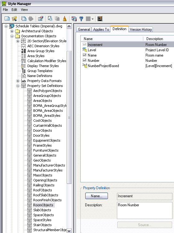
In Autodesk Architectural Desktop 2006 and earlier, the RoomObjects Property Set Definition held these properties; in Autodesk Architectural Desktop 2007, the SpaceObjects Property Set Definition does. Autodesk Architectural Desktop 2006 had a SpaceObjects Property Set Definition, but it was identical to the SpaceStyles Property Set Definition, and contained automatic properties associated with Spaces.

ADT 2006 Room Objects Property Set Definition


ADT 2007 Space Objects Property Set Definition


If you migrate previous drawings to 007, be certain to rename the RoomObjects Property Set Definition to SpaceObjects if you want to use the 2007 out-of-the-box tags. If you migrate both old drawings and old content, you would not have to make the change, but keep in mind that other Property Set Definitions with Location properties may also reference the room properties, so either bring all of your old sets and content or be prepared to edit property references if you mix and match.

If you have a custom tag that you want to use with the 2007 Property Sets, make a copy of the content file for use in 2007 [unless you will never use a previous version ever again], and then edit the view blocks, changing the attribute tag names to refer to the SpaceObjects Property Set Definition, rather than the RoomObjects Property Set Definition.

Also note that the "Name" property is no longer a manual property but now references a newly added automatic property source, which can be filled in on the Design tab of the Properties palette, in the General subheading of the Basic category. You can assign a List Definition that applies to Space Names if you like, to make it easier to enter names in a consistent manner. If you prefer multi-line tags that use multiple attributes for multiple lines, you will have to add the needed properties and create/migrate your custom tag.

July 01, 2006

More Updates & Service Packs


In addition to the updated tutorials, the following were recently added to the Autodesk Architectural Desktop Updates and Service Packs page for Autodesk® Architectural Desktop 2007:

Hotfix - Fatal Error During Save Published: 2006-06-14
Hotifx - Cut and Paste Published: 2006-06-30
Certified Hardware XML Database Update Published: 2006-06-12

Note that you need only update the acdb17.dll file from one of of the two Hot Fixes, as either currently provides version 17.0.103.50 of that file.

Revised Tutorial Files for ADT 2007


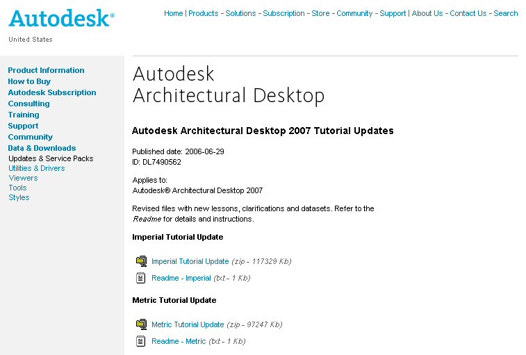
Revised Imperial and Metric tutorial files for Autodesk Architectural Desktop 2007 have been posted to the Autodesk website for downloading. According to the Imperial Readme file:

Autodesk Architectural Desktop 2007 Imperial Update Tutorials

Revised imperial tutorials with new lessons and exercises in printable PDF format.
Datasets for the new lessons included in the updated tutorials. Download the datasets to c:\Program Files\Autodesk Architectural Desktop 2007\ Tutorial\Architectural Desktop\Datasets.

Files included in this package:
  • adt_imperial_tutorials.pdf - PDF file containing updated imperial Autodesk Architectural Desktop 2007 Tutorials.
  • Getting Started_I.dwg - Getting Started tutorial dataset.
  • A4A_I.exe - Autodesk Architectural Desktop: Making AutoCAD Better for Architects tutorial dataset.
  • Small Office Building_I.exe - Small Office Building tutorial dataset.
  • Steel-Framed Residence_I.exe - Creating a Steel-Framed Residence tutorial dataset.

If you customized file locations when installing ADT 2007, you would want to place the datasets in the same folder(s) as the original datasets.

June 30, 2006

Google Earth Extension for ADT 2007 Public Beta


Shaan Hurley has announced the availability of a new public beta on the Autodesk Labs site, the Google Earth™ Extension for AutoCAD 2007, Architectural Desktop 2007, Autodesk® Civil 3D® 2007, and Autodesk Map 3D 2007.

June 24, 2006

Automatically Displaying a Viewport’s Scale

For those not using Project Navigator and the Callouts that are linked to a Model Space View, there are two ways to display the scale of a viewport that will update "semi-automatically". Users of Autodesk Architectural Desktop 2004 or later can use Formula properties to obtain and format the viewport scale. Users of Autodesk Architectural Desktop 2005 and later can use a field in Text, Mtext or an Attribute attached to a Block Reference. Each method has its advantages and disadvantages; use the method that works best for you and your workflow.

A sample file created in ADT 2006 that contains examples of both techniques has been posted to this thread in the Autodesk Architectural Desktop Dicussion Group. The content in that file is not meant to be finished content suitable for project use, but was developed solely to demonstrate that the ideas work. Testing of the content was fairly limited; should you choose to adapt any of it for your own use, please test it thoroughly to be certain it performs as you expect.

Fields
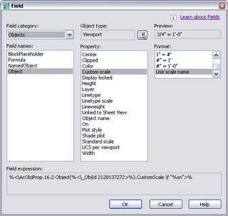
Setting up a field is certainly easier than setting up the formulas and tags. I used Dtext to hold the field, but you could add it to an attributed block just as easily. After adding the field or attributed block with the field, you will need to edit the field. Choosing the Object Field Name, use the Select Object button to select the desired viewport, select the Custom Scale Property and choose your desired Format. The 2006 version of the dialog can be seen in the image below.
I noted the following with respect to using fields:
  • Formatting in fields is "static" - you pick one of the given formats and that is how the scale is displayed. For example, Imperial "architectural" scales are usually given in terms of the distance that represents 1’-0" [1/4" = 1’-0"], while "engineering" scales are given as the distance that 1" represents [1" = 50’-0"]. There are formats for each type, but you would have to manually set that for each field. The 1" = #’ format only shows the distance as feet, not feet and inches.
  • If the scale factor of a viewport is close but not quite an exact "typical" scale, the value may round to a "typical" scale value, masking the error.
  • The #" = 1’-0" and #" = 1’ formats will always express any fractional number with a denominator that is 2 raised to some power [halves, quarters, eighths, etc.]. You will not get 1/10" = 1’-0", but 13/128" = 1’-0", which is not an exact expression of the scale.
  • 2006 and 2007 offer a formatting option, "Use scale name", that overcomes the previously mentioned issues by displaying scales that have been entered into the Scale List using the scale name. You will have to enter all of the scales you expect to use in the Scale List, but you would probably want to do that anyway. Viewport scales that do not match a value associated with a scale on the list are displayed as the raw custom scale number, making it easy to spot viewports which have "close, but not quite" scales. 2005 lacks this option, as well as the option to express Imperial scales as 1" = a number of feet.

Formulas
You can retrieve the CustomScale property for a viewport object using a Formula property that is part of a Property Set Definition attached to the viewport. You can then format that value however you like, provided you are willing to write the code to do so. There is also a StandardScale property, which returns an integer that is likely related to the Scale List, but in the time I spent looking at this, I was not able to work out how to take that number and use it to get the associated scale name.

The following assumptions were made in developing the sample Formula properties. If your situation varies, you may need to adjust the formulas to suit.
  • Drawing units for Imperial are inches and for Metric are millimeters. Other base units may require adjustments to compensate.
  • Metric scales are expressed as ratios of plotted units to real-world units, with one side or the other set to 1.
  • Imperial scales are expressed as fractions of an inch equal one foot, when the fractions of an inch can be given as a whole number of 256ths of an inch. The fraction is reduce to the lowest possible denominator. Otherwise, Imperial scales are given as 1" = a number of feet and inches.

The ViewportObjects Property Set Definition in the sample file contains the following properties:
  • DetailNumber - A text-type Manual property for entering a detail number.
  • DetailTitle - A text-type Manual property for entering a detail title.
  • Handle - An Automatic property that references the Handle automtatic property source. This property is used to get the viewport object in the ViewportScale Formula property.
  • Measurement - A Formula property that gets the value of the Measurement System Variable. This is used to determine if the viewport scale should be formatted for Imperial [value is 0] or Metric [value is 1].
  • ViewportScale - A Formula property that gets the value of the viewport's CustomScale property, and returns the inverse of that value.
  • ViewportScaleString - A Formula property that takes the value in the ViewportScale property and formats it, based on the Measurement property value and the ViewportScale value. Metric scales are expressed as a ratio of plotted units:real-world units. When each plotted unit represents more than one real-world unit [typical in architectural drawing], this results in 1:[scale factor]. For that rare case where you are showing a detail at larger than full-size, the scale is given as [1/scale factor]:1. Where Imperial scales can be expressed as a whole number of 256ths of an inch = 1'-0", that format is used, otherwise, the scale is expressed as 1" = feet and inches.

I chose to use two separate properties, one to get the scale value, and another to do the formatting, to make it easier to test these two functions. You could just as easily use one formula and eliminate any issues that might arise when reading the ViewportScale value into the ViewportScaleString property, such as the reduction of the precision to a maximum of eight decimal places.

The Measurement formula reads in the value of the MEASUREMENT System Variable, using this formula:
Set acadApp = GetObject(,"AutoCAD.Application")
RESULT = acadApp.ActiveDocument.GetVariable("MEASUREMENT")


The ViewportScale formula gets the viewport object using the Handle Automatic Property Source. Since viewports are in paper space, there will be no issue with the Handle source not working across externally referenced files; using Handle lets the same formula work in any version since the introduction of the Formula property in ADT 2004. Once the viewport object is in hand, getting the CustomScale object and taking its inverse is easily done.
Set acadApp = GetObject(,"AutoCAD.Application")
Set pViewportObj = acadApp.ActiveDocument.HandleToObject( "[Handle]" )
RESULT = 1 / pViewportObj.CustomScale


The ViewportScaleString property uses the value from the ViewportScale property and performs the formatting need to create the string to be displayed. As shown in the code below, the first test is for whether the drawing is using Metric or Imperial, based on the value in the Measurment property [MEASUREMENT System Variable value].
scaleFactor = [ViewportScale]

If [Measurement] = 1 Then
' Metric drawing
If scaleFactor > 1 Then
scaleFactor = Fix( scaleFactor * 10000.0 ) / 10000.0
RESULT = "1 : " & CStr( scaleFactor )
Else
inverseScaleFactor = Fix( 10000.0 / scaleFactor ) / 10000.0
RESULT = CStr( inverseScaleFactor ) & " : 1"
End If
Else
'Imperial drawing
'If 12.0/scaleFactor is a whole number of 256ths, return string as that
'fraction, reduced to lowest denominator = 1'-0"; otherwise, return string as
'1" = feet (and inches).

inchesPerFoot = 12.0 / scaleFactor
maxNumerator = inchesPerFoot * 256.0
If ( maxNumerator - Fix( maxNumerator ) ) = 0 Then
minNumerator = maxNumerator
powerOfTwo = 0
tempNumerator = minNumerator / 2.0
Do While tempNumerator - Fix ( tempNumerator ) = 0.0
powerOfTwo = powerOfTwo + 1
minNumerator = tempNumerator
If powerOfTwo = 8 Then
Exit Do
End If
tempNumerator = minNumerator / 2.0
Loop
minDenominator = 256.0 / 2^powerOfTwo
RESULT = minDenominator
wholeTotalInches = Fix ( minNumerator / minDenominator )
properInchesNumerator = minNumerator - ( wholeTotalInches * minDenominator )
wholeFeet = Fix ( wholeTotalInches / 12.0 )
wholeInches = wholeTotalInches - (wholeFeet * 12.0)

If wholeFeet = 0 Then
strWholeFeet = ""
Else
strWholeFeet = CStr( wholeFeet ) & "'-"
End If

If (wholeInches = 0) and (wholeFeet = 0) Then
strInches = CStr( properInchesNumerator ) & "/" & CStr( minDenominator )
Elseif properInchesNumerator = 0 Then
strInches = CStr( wholeInches )
Else
strInches = CStr( wholeInches ) & " " & CStr( properInchesNumerator ) & "/" & CStr( minDenominator )
End If

RESULT = strWholeFeet & strInches & Chr(34) & " = 1'-0" & Chr(34)

Else
wholeFeet = Fix( scaleFactor / 12.0 )
inches = ( Fix( ( scaleFactor - ( wholeFeet * 12.0) ) * 10000 ) / 10000 )
RESULT = "1" & Chr(34) & " = " & CStr(wholeFeet) & "'-" & CStr( inches ) & Chr(34)
End If
End If


Please note the following with regard to rounding: The ViewportScale property returns the inverse of the CustomScale property of the viewport, with up to eight-decimal places. The ViewportScaleString arbitrarily cuts off formatted Metric scales and Imperial scales using the 1" = feet and inches format to four decimal places without rounding. This should not be an issue if your viewport scale is a standard scale with a whole number scale factor; displaying some fractional value can help identify viewports that have been incorrectly set up or modified.

Updating of the Scales – Field and Formula
If you have read this far, you may have forgotten my use of the term "semi-automatic" way back in the first paragraph to describe the updating of the scale properties. Here is what I observed in my sample file, during the limited testing that I did. The values do not always update instantaneously; I did not test what would happen when plotting the file with a value that had not been updated. If you have all of the "Automatically update field values" options selected [User Preferences tab of the Options dialog] - including Plot - I would not expect to have a problem with fields, but you would certainly want to test this before using it in a production environment.
  • Changes made to the scale of a viewport using any of the following methods routinely did not automatically update the scale value in the Schedule Tag or in a field. REGEN [REGENALL from Model Space] updated a field in MTEXT; OBJRELUPDATE was often needed to update the Schedule Tag [and also works on fields].
    • ZOOM command in Model Space of the viewport [all options, including real time].
    • Rolling the mouse wheel in Model Space of the viewport.
    • Viewport Scale Control [a toolbar control that is a feature of the ACAD.cui Viewports toolbar], in Model Space or Paper Space. ADT does not include this toolbar, so this may not be an issue for you unless you have the ACAD.cui loaded, have transferred the Viewports toolbar to the ADT.cui or have added the Viewport Scale Control to a custom toolbar of your own.
  • Changes made to the scale by selecting the viewport in Paper Space and using the Properties palette appear to be udated immediately in a Schedule Tag; a REGEN is required to update a field. Note: On occasion, but not consistently, I have seen changes made using the Custom property not automatically update in a Schedule Tag. In these cases, a REGEN has updated that tag value.
  • Changes made to the scale by selecting the viewport in Paper Space and using the VP Scale list on the Drawing Window Status Bar appear to be updated immediately in a Schedule Tag; a REGEN is required to update a field. Note: On occasion, but not consistently, I have seen changes made using the Custom option not automatically update in a Schedule Tag. In these cases, a REGEN has updated that tag value.
  • Changes made to the scale in Model Space and using the VP Scale list on the Drawing Window Status Bar appear to be updated immediately in a Schedule Tag; a REGENALL is required to update a field [or change to Paper Space and use REGEN]. Note: On occasion, but not consistently, I have seen changes made using the Custom option not automatically update in a Schedule Tag. In these cases, a REGENALL has updated that tag value.

One other note of caution: Do not use this with multiple versions of Architectural Desktop running - not simply installed, but with separate instances of multiple versions actually running - on the same computer simultaneously. I experienced "lock ups", where not only the Schedule Tag, but the Property Data as displayed on the Properties palette, remained fixed on the initial value, even after saving, closing and reopening the file. Closing all but one instance of one version of Architectural Desktop and reopening the file restored the ability of the properties to update.

June 17, 2006

Separating Structural Shape Names in a Complex Structural Member Style

Structural Member Styles can have up to ten components. The Shape Designation - List Automatic Property Source returns a "list" of the starting shapes used by the components of a Structural Member Style. The name of each shape appears in order, separated by a semicolon from the other shapes. For example, a steel column shape with three components, a 12x12 base plate, a W8x28 column and a 12x12 top plate, would be listed as "12x12;W8x28;12x12", assuming that "12x12" and "W12x28" were the shape names for the plate and column components.

If you wanted to create a tag that listed a particular shape name, or had some other need to have access to the individual shape names, you can use a series of Formula properties, one for each component/shape name. A sample file with one approach to doing this has been posted in response to a question raised in my AUGI Training Program course on Formula Properties [ATP121]. To assure access to the file after the course concludes, I have also posted the file to this thread in the Autodesk Architectural Desktop Content Discussion Group.

In the formulas, the first thing I did was to append a semicolon onto the end of the string returned by the Shape Designation - List Automatic Property Source. This creates a string in which every shape name is followed by a semicolon and allows every shape name to be processed in the same way.

While similar formulas could be used for all ten shape names, I chose to simplify the first formula as no initial processing of the string is required; all that is needed is to extract the first shape name in the string. The VBScript Left function is used to do the extraction; the InStr function is used to determine the character position of the first semicolon, and one is subtracted from that to return just the first shape name. Here is the formula for the first structural shape name:
shapeList = "[ShapeDesignation-List]" & ";"
RESULT = Left( shapeList, InStr( 1, shapeList, ";", 0 ) - 1 )


The formulas for shape names two through ten are identical, except for the value set assigned to the shapeNumber variable, which determines which shape name gets returned [2 = second shape name, 3 = third shape name, etc]. A Do While Loop statement is used to execute the code that removes the leading shape name and its trailing semicolon until the desired shape name is at the head of the string. Then the resultant string is processed using the same code as used in the formula for the first shape name. There is one extra wrinkle here, to accommodate Stuctural Member Styles that use less than ten components - after each truncation, the resultant string is tested to see if it is an empty string. If so, the Do While Loop is immediately exited. An empty string is returned if there is no component assigned to that number, otherwise the shape name is returned. Here is the formula for the second through tenth structural shape names, shown for the tenth name:
shapeList = "[ShapeDesignation-List]" & ";"
shapeNumber = 10
loopCount = 1
Do While shapeNumber > loopCount
shapeList = Mid( shapeList, InStr( 1, shapeList, ";", 0 ) + 1 )
If shapeList = "" Then
Exit Do
End If
loopCount = loopCount + 1
Loop

If shapeList = "" Then
RESULT = shapeList
Else
RESULT = Left( shapeList, InStr( 1, shapeList, ";", 0 ) - 1 )
End If


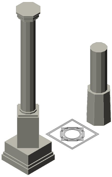
The sample file contains a ten-component Structural Member Style called TestColumn, and a two-component Structural Member Style called TestColumn2, samples columns using these styles are shown below.

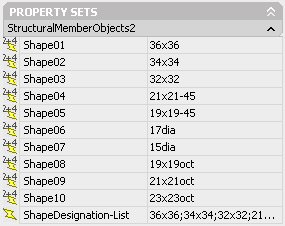
The style name property values for the ten-component style looks like this:

The style name property values for the two-component style looks like this:

June 10, 2006

Tag for Polyline-based "Rooms"

In response to a question in the Autodesk Architectual Desktop Content Discussion Group, I have posted a ZIP file containing a sample file and an AEC Content Schedule Tag file done in ADT 2005 showing that you can, if you like, use polylines to represent the outline of a room and set up a Property Set Definition and Schedule Tag that will display a room name, room number and room area.

If something like that would interest you, check it out in this thread.