October 31, 2006

Multi-View Block Creation

There have been a number of posts in the Autodesk Architectural Desktop Discussion Groups over the years asking for help in the creation of Multi-View Block Definitions. If you can create an AutoCAD block definition, then you are most of the way there. I am going to assume that you do know how create the AutoCAD blocks that will be used for the Multi-View Block, and will focus on a few tips on creating the blocks and then run through the process of creating the Multi-View Block Definition.

Terminology
  • MVB - abbreviation used in balance of article for Multi-View Block.
  • view block - an AutoCAD block definition assigned to one or more view directions for one or more Display Representations.
  • view direction - direction from which the ADT model is being viewed. MVBs allow assigning blocks to be displayed when one of the orthogonal view directions [Top, Bottom, Front, Back, Left or Right] is active, as well as one for "Other" view directions.
  • WCS - World Coordinate System, a fixed coordinate system used as the basis for defining all objects and other coordinate systems.
When creating a MVB, you need to consider what the purpose of the MVB is and under what conditions it needs to be visible. For example, a Schedule Tag may only need to be seen from the Top view direction, and a single view block may be sufficient. Other MVBs may depict a symetrical object that can use the same view block for more than one view direction. The example shown here assumes a 3D object is to be represented, with a unique view block for each orthogonal direction, as well as a "3D Block" made with a Mass Element.

The two most important things to keep in mind when creating the view blocks for your MVB are:
  • Maintain an insertion point for all view blocks that is consistent in all three dimensions, preferrably at the MVB insertion point.
  • Set the World Coordinate System current when defining the view blocks. The graphics for each orthogonal view block need to be drawn in the plane from which they will be viewed [World X-Y plane for Top and Bottom views, World X-Z plane for Front and Back views and World Y-Z plane for Left and Right views]. It may be advantageous to set an UCS that places the UCS X-Y plane parallel to the plane in which you wish to draw the graphics for a particular view block, but you MUST CHANGE BACK to the WCS before defining the view blocks!
I find it easiest to achieve both those goals when creating a new MVB by drawing a series of lines in the X-Y WCS, with one endpoint of each line at WCS Y= 0. One of the preset isometric views, such as the southwest view shown in the image below, provides a handy viewpoint for drawing the block graphics, getting them positioned correctly and getting a consistent insertion point. It also allows you to use the graphics from one view block as a starting point for drawing the graphics of the others.

You will also want to give consideration as to whether your MVB needs to display differently when different Display Representations are active. Perhaps your object should have a different top view displays for a regular plan and a reflected ceiling plan. If you have your Display System set up with two Display Representations for MVBs, one of which is only active in the Display Configuration[s] you use for regular plans and the other one of which is only active in the Display Configuration[s] you use for reflected ceiling plans, then you can create separate view blocks and assign each to the Top view direction in its corresponding Display Representation. Also remember that, unlike other ADT objects, the display control for MVBs is limited to assigning view blocks to view directions for the available Display Representations and then choosing which Display Representation[s] to have active for a given Display Representation Set. You can not control layer, color, linetype or plot style as a display setting; you need to set those up in the graphics of the view block. For example, if you want your MVB to plot screened when the Screened Display Represenation is active, then the graphics you use in the view block[s] assigned to the Screened Display Representation must be set up to plot screened, either by direct plot style/color assignment or by using ByLayer graphics on a layer that plots screened. My example MVB has the graphics in the view blocks all set to ByBlock, so that they will inherit the layer, color, linetype, etc, of the parent MVB.

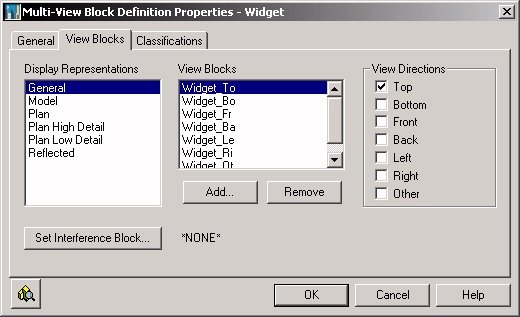
Once the view blocks are defined, the hard work is over. Open up the Style Manager and create a new Multi-View Block definition. Give the definition an appropriate name and description on the General tab. Then select the View Blocks tab, where you will assign the view blocks you created to the appropriate view directions for each Display Representation in which your MVB is to be visible. In my example file, the General Display Representation is used to display the othogonal view blocks, with the "3D block" assigned to the other view direction. The Model Display Representation has the "3D block" assigned to all view directions. Select the desired Display Representation in the left list box, then use the Add... button to select a view block. When adding a view block, the initial default is for all view directions to be selected; left click on the view direction toggles at the right to set or clear each view direction for the selected view block. The images below show the General Display Representation settings for the Widget_To [Top view block], Widget_Fr [Front view block], Widget_Le [Left view block] and Widget_Ot [Other view block]. The settings for the other view directions are similar, with the each block assigned to the appropriate view direction.


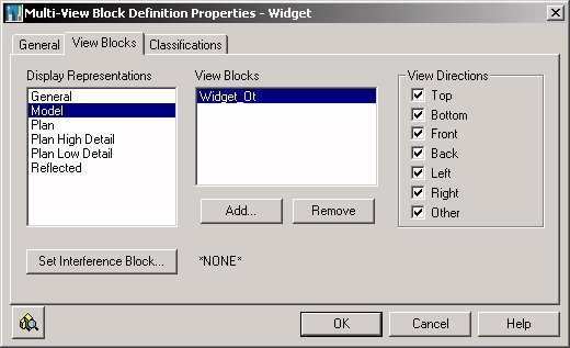
The following image shows how the Widget_Ot view block has been assigned to all view directions for the Model Display Represenation.

Select the OK button in the MVB Definition Properties dialog and the OK button in the Style Manager to save your MVB Definition to your drawing. Now would be a good time to save the drawing file, too.

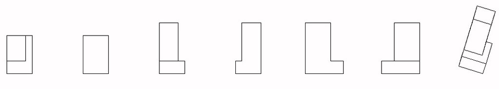
Having defined a new MVB, you will want to test it before using it yourself or distributing it to others. The image below shows a new set of orientation lines, this time with the MVB inserted at the endpoint, then rotated in three dimensions so that, when viewed from the Front predefined view, all seven view blocks will be active at the same time. This allows you to make certain all view blocks were assigned, the correct view block was assigned to each view direction and the view block is properly oriented.

The image below is the result of changing to the Front view and shows that the MVB was created correctly.

October 03, 2006

Auto-Import Layer Key Style

Autodesk Architectural Desktop provides a way to make certain the Layer Key Style in your drawing files reflects the latest revisions without having to manually import the revised Layer Key Style [or even to know that it has been updated]. The image and procedures shown here were created/developed for ADT 2004, but the same feature is available in later releases.

The Layering tab of the Drawing Setup dialog allows you to specify a Layer Standards/Key File to Auto-Import. If you have not done so already, you will want to establish a file to hold your Layer Standard[s] and Layer Key Style[s]. The AecLayerStd.dwg file holds the out-of-the-box Layer Standards and Layer Key Styles. For the 2004 release, on a standalone, local machine installation, this file is located at:

C:\Documents and Settings\All Users\Application Data\Autodesk\Autodesk Architectural Desktop 2004\R16.0\enu\Layers

The path will be similar, with some minor variation in later releases. If you have a customized installation, particularly if some files were placed on the network for common access by all users, this file could be anywhere, but is likely located with your other content files.

If you have customized or plan to customize either the Layer Standard or the Layer Key Style[s], I would highly recommend starting with a copy of the AecLayerStd.dwg file, renamed to reflect that it has your firm's customizations, to make migration to new releases easier. Be certain to back up any customizations, whether to the AecLayerStd.dwg file or your own custom file.

Having identified the name and location of your central source file for Layer Standards and Layer Key Styles, you will want to make that your Auto-Import file by selecting the ellipsis [...] button to the right of the Layer Standards/Key File to Auto-Import area, navigating to your file and selecting it.

Next, set the Layer Key Style from your source file that you wish to be current, using the dropdown list in the Default Layer Standard area. Then note the toggle at the bottom of that area, labeled "Always import Layer Key Style when first used in drawing". Check that toggle if you wish to automatically update your drawing file with any future changes made to the Layer Key Style in the source file. If you want that to be the default condition for all drawings opened on that computer, for that users, also check the Save As Default toggle in the lower left corner. [You may want to check the settings on the other tabs to be certain they have the desired initial default values set before hitting OK, as the Save As Default toggle affects the entire dialog box.]

Here is how this feature works. The first time you issue an ADT command in a given editing session for that drawing [and any other in which the Always import Layer Key Style when first used in drawing toggle is checked], ADT will check the file specified as the Layer Standards/Key File to Auto-Import to see if the Layer Key Style has been edited and saved more recently than the current drawing file. If so, it will automatically import the Layer Key Style from the source file before making use of the referenced Layer Key. If not, the Layer Key Style in the drawing file will be used. No additional checks on the Layer Key Style will be made during that editing session. If you are told the Layer Key Style has been updated while you are editing a file, you can either use the Style Manager to update it from the source file manually, or save [if you want to keep any unsaved changes], close and reopen the file.

This feature is particularly valuable if you are just implementing ADT and make frequent changes to the Layer Key Style to get things "just right" for your office at the same time others are using ADT for production work.