May 26, 2007

Drawing Accurately

I can not stress enough the importance of drawing accurately when using Autodesk® Architectural Desktop, AutoCAD® Architecture, or even AutoCAD®, for that matter. Nearly all of my work is done in imperial units, and when creating "the model" (or just "drawing"), I generally keep my units set to Engineering (feet, inches and decimal inches) and the precision set to at least five decimal places, to avoid having small errors being masked by the rounding that takes place when using architectural units.

I often hear, "Why bother, it will not be built with that level of accuracy in the field and the precision on the dimensions is set to 1/8" anyway?" I understand that in the field, getting to within 1/4" of the design is a very good day, and that any given wall is not straight, nor are any two walls perpendicular or parallel. Your design needs to make allowances for construction tolerances, particularly when a more precise item, such as a factory produced object, is installed adjacent to a less precise item, like a field-built wall. I would argue that you still want to draw accurately so that you know what dimension you "should" have, and then apply your tolerances to that.

One very important reason is that Autodesk Architectural Desktop/AutoCAD Architecture objects can do some strange things when they are not drawn precisely. (And, as Larry Bettes notes in the Discussion Group thread noted below, not only should the objects be drawn precisely, but you want to start from a point that is a whole number, or at least does not require all 16 of the significant figures available.) Another important reason is if you draw your model accurately, you can query the model for information and have a reasonable level of confidence that the information you get back is accurate. Is it just me, or are the very people who draw with the precision set to a large value or "eyeball" when placing a new object or moving an existing one ("Snaps, what are those?" "Keying in a distance takes too much time!") the very same people who think you can take that inaccurate model and blindly add dimensions and everything will be just fine? Perhaps the error between any two adjacent walls is small, and less than construction tolerances, but when you have a number of such inaccuracies added together, you can not always count on them cancelling each other out.

Here is one example of how small imprecisions can add up to sizable error. The total error in this example is small, but keep in mind the precision on the dimension strings is 1/64", and in one foot the error is already four times that. The images below are based on a file I created and posted to this thread in the Autodesk Architectural Desktop 2007 & Prior Discussion Group.

I did modify the dimension style to use the Arial text style and bumped the DIMSCALE up to 2 so that the numbers would be more easily seen in the screen captures.

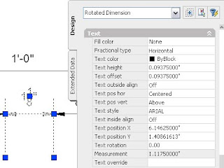
I started with a dimension style that has its precision set to 1/64" and drew a dimension exactly 1'-0" long. As you can see in the image below, the Measurement property of the dimension indicates 1'-0.00000000".
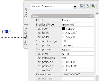
Then I added eight dimensions, each of which displays 1 1/8" as the dimension value (no text overrides here, trust me).

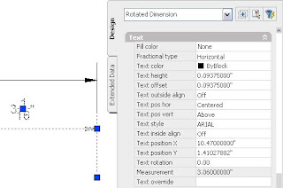
Given this, you would expect a closing dimension to show 3", since 1'-0" - (8 * 1.125") = 3". But you would be wrong, as can be seen below.

How did the closing dimension end up being 3 1/16"? Simple: all eight of the 1 1/8" dimensions are identical, and as shown below, are NOT exactly 1.125", but are instead 1.1175". This makes each one just less than 1/128" shy of 1 1/8" (and therefore just over 1/128" more than 1 7/64"), so the value rounds up to the nearest 1/64", or 1 1/8". This gives the impression of 1/8" accuracy without the substance, and allows the closing dimension's measurement, 3.06000000, to be reported at 3 1/16".
So a series of small inaccuracies can add up to a significant one. And while the difference may still be relatively minor, the point is that by drawing inaccurately, you are allowing the person doing the layout on site to determine where any extra dimension goes or where any missing dimension is taken out. Nine times out of ten you may not care. But that tenth time, when the expensive piece of millwork does not fit, you will care, but it will be too late. If you work on a team with others who rely on the accuracy of your work to do their work, you may find that you care even sooner. With all of the tools at hand in Autodesk Architectural Desktop/AutoCAD Architecture, it really does not take that much additional effort to draw accurately, and the time you save chasing dimension strings that do not add up and dealing with layout issues in the field will more than make up for the extra effort. And you may see fewer wall cleanup issues, to boot!
May 10, 2007

Cycling Between Viewports in a Layout

Those of you who used Autodesk® Architectural Desktop prior to the introduction of the Customize User Interface (CUI) files in 2006 may recall that the menu file included an "accelerator" for the CTRL+R keystroke combination that would cycle between the viewports in a layout whose extents are at least partially visible on-screen. Those of you who have been using AutoCAD® for many years may also recall that the "original" accelerator was CTRL+V [or ^V in a menu macro], which got supplanted when Windows came along and made CTRL+V "paste".

The ability to cycle through the viewports can be handy when you have overlapping viewports and the program decides the one you want is "underneath" the one you do not want, and is essential if you have an "underneath" viewport that is entirely within the boundaries of another viewport. For whatever reason, the CTRL+R accelerator did not get incorporated into the ADT.cui file, so users of 2006 and later may find they no longer can cycle through viewports using CTRL+R. The good news is nothing else has been assigned to CTRL+R, and it is not difficult to add the CTRL+R functionality back.

In CUI files, the old accelerators are now called Shortcut Keys and are found under the Keyboard Shortcuts category of a given CUI. You can add Shortcut Keys to the main CUI or any partial CUIs you may have loaded; if you have a separate CUI for your company standard menu items or for your personal use, you may want to add the CTRL+R Shortcut Key there, to aid in migrating to future releases. The Help contains instructions for how to add a Shortcut Key, and there is even a video in the 2007 Help for those of you who are visually oriented. You can find this by navigating here: AutoCAD Help > Customization Guide > Customize the User Interface > Add Shortcut Keys and Temporary Overrides. In 2006, click on the Procedures tab, then select the "To create a shortcut key" link. In 2007, the video is on the "Add Shortcut Keys and Temporary Overrides" page.

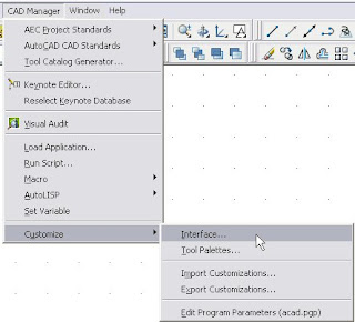
For those who have an allergic reaction to the Help, or who find the fact that the instructions are written around the ACAD.cui, not the ADT.cui too annoying to bear, the balance of this article covers the specifics of adding the ^V macro as a Shortcut Key and assigning the CTRL+R keystroke to it. The first thing you will need to do is open the Customize User Interface dialog. Type CUI at the Command: prompt. If you hate keyboarding and want to use a pulldown menu, you will not be able to use the Tools pulldown, as noted in the Help [unless you have added that from the ACAD.cui file]. If you have added the CAD Manager pulldown menu [Window > Pulldowns > CAD Manager Pulldown] you can start the CUI command from there, as shown below. [As always, you can view a full-size version of reduced size images by clicking on the image.]

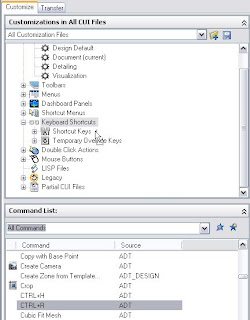
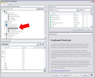
Set the Customize tab active, if it is not already current. The upper left pane of the Customize tab lists the CUI files that are loaded. You can choose to show all CUI files, or focus on one using the dropdown list at the top of the pane. Expand the CUI in which you want to add the CTRL+R Shortcut Key and then expand the Keyboard Shortcuts category, as shown below. You will not see the large red arrow, which I added to the image for emphasis.

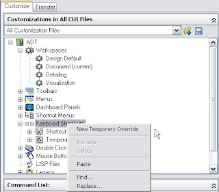
Here is a tip for those of you who have fully embraced the AutoCAD® Architecture/Autodesk Architectural Desktop mindset of right-clicking to do just about anything. In this case, it will not work. You can right click on either "Keyboard Shortcuts" or "Shortcut Keys" and a context menu will obediently appear, but there will not be an option to add a new Shortcut Key, as can be seen in the image below.

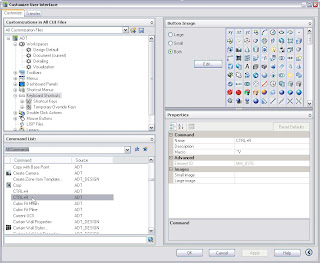
New Shortcut Keys are created by dragging the command you want from the Command List in the lower left pane of the CUI dialog and dropping it onto "Shortcut Keys" in the upper left pane. Fortunately for our example, there is alread a "command" in the Command List, named "CTRL+R", that has the ^V macro assigned to it, so we do not need to add a custom command to the list. Scroll down in the Command List list box until you see the "CTRL+R" command.

Left click on and then drag the "CTRL+R" command up to "Shortcut Keys" in the upper left pane and drop it there.

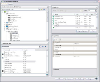
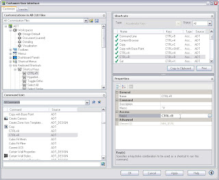
Expand the Shortcut Keys subcategory, if it did not do so automatically while you were dragging and dropping, and then find and select your new "CTRL+R" command on the list of commands. This will change the display on the right side of the Customize tab of the CUI dialog, displaying "Shortcuts" in the upper right pane, with a list of all of the Shortcut Keys commands, and "Properties" in the lower right pane. Since you selected "CTRL+R" command in the upper left pane, it is highlighted in the upper right pane and the Properties pane shows the properties for that command. Notice the horizontal bar in the left column in the Shortcuts pane, rather than the check mark that the other commands have. That is because a keystroke has not been assigned yet.

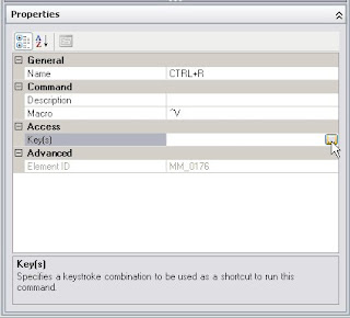
To assign a keystroke, click in the right column next to the "Key(s)" line in the Access category of the Properties pane. An ellipsis button will appear at the right side of that line; select it to open the Shortcut Keys dialog.

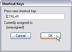
The Shortcut Keys dialog allows you to indicate what keystroke combination you want to assign to this command. Click in the edit box, if the focus is not already there, then press the "CTRL" and "R" keys at the same time, to enter "CTRL+R". The dialog will tell you what command is currently assigned to that keystroke combination, if any. If you are satisfied with the entry, select OK to return to the CUI dialog box.

You have now assigned a keystroke combination to the CTRL+R command, and the Shortcuts pane now shows a checkmark in the first column on that line, as well as the assigned keystroke combination in the Keys column. Select the Apply button to save this change to the CUI, if you have additional changes to make, or select OK to save the change and return to the drawing file.

You should now find pressing CTRL+R when model space is active on a Layout with multiple viewports visible on screen will cycle through those viewports. You will want to back up the CUI file in which you made the change, to avoid having to do it again in the future, should you ever "lose" that file.