December 04, 2020
Revit: Text Parameter Value Driven by Four or More Yes/No Parameters
Regarding my last post, I would be remiss if I did not point out that FAIR59 also replied, with a more elegant solution that is also easier to expand to 5, 6 or more parameters. Check out that post here.
December 01, 2020
Revit: Text Parameter Value Driven by Four Yes/No Parameters
I came across an interesting request in the Autodesk Revit Architecture forum the other day. The person wanted to have four Yes/No parameters (called A, B, C and D) determine the value of a text parameter (called TEXT), based on the following conditions:
The solution I devised uses a series of nested if statements to work through all of the possibilities. The condition of the first if statement is an or. Each item in the or is an and of a pair of the Yes/No parameters. There is an and for each possible combination of the four Yes/No parameters. If both items in at least one of the combinations of Yes/No parameters is true, then the entire or evaluates to true. That takes care of all of the situations where two or more of the Yes/No parameters are checked, and "SELECT ANY ONE" is returned.
The else of the first condition then launches a series of if statements that tests whether a given Yes/No parameter is checked, starting with A. If A is checked, "A" is returned; if not, another if statement tests for a check in B. If B is checked, "B" is returned, and so on through to D. If D is checked, "D" is returned; if not, "NO TEXT" is returned.
Here is the formula:
And a screen capture:
- If two or more of the four Yes/No parameters are checked, the value of TEXT is to be "SELECT ANY ONE".
- If none of the four Yes/No parameters are checked, the value of TEXT is to be "NO TEXT".
- If only the A parameter is checked, the value of TEXT is to be "A".
- If only the B parameter is checked, the value of TEXT is to be "B".
- If only the C parameter is checked, the value of TEXT is to be "C".
- If only the D parameter is checked, the value of TEXT is to be "D".
The solution I devised uses a series of nested if statements to work through all of the possibilities. The condition of the first if statement is an or. Each item in the or is an and of a pair of the Yes/No parameters. There is an and for each possible combination of the four Yes/No parameters. If both items in at least one of the combinations of Yes/No parameters is true, then the entire or evaluates to true. That takes care of all of the situations where two or more of the Yes/No parameters are checked, and "SELECT ANY ONE" is returned.
The else of the first condition then launches a series of if statements that tests whether a given Yes/No parameter is checked, starting with A. If A is checked, "A" is returned; if not, another if statement tests for a check in B. If B is checked, "B" is returned, and so on through to D. If D is checked, "D" is returned; if not, "NO TEXT" is returned.
Here is the formula:
if(or(and(A, B), and(A, C), and(A, D), and(B, C), and(B, D), and(C, D)), "SELECT ANY ONE", if(A, "A", if(B, "B", if(C, "C", if(D, "D", "NO TEXT")))))
And a screen capture:

November 25, 2020
Revit: Extracting Level Names in Dynamo
A few weeks back, I had a request to be able to filter a Door Schedule by the Level to which the Doors in the project were associated. That is a choice if you are only scheduling Doors in the current model, but is not an option if your Schedule includes Doors in linked models. I suggested that a Dyanmo graph could be created that would read the Level of each Door and write the Level name to a separate parameter, which could then be used for filtering. The graph would need to be run in each of the models, and, if there are later changes that add more Doors, re-run. Pretty standard stuff for a Dynamo graph.
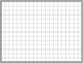
There is just one problem with that - the built-in Revit parameter Level does not return just the name of the Level, but instead returns what is shown in the image below.
I ran those results through the String from Object node to be certain the values were seen as strings. (I suppose I should try it without that node to see if it is really necessary, but I have not done so yet.) It may be possible to extract the level name for each item on the list using a series of nodes, or perhaps some code in a code block, but the amateur programmer in me wanted to work out how to do so in Python, and it turned out be be quite simple, using string slicing. The start index of the Level name is one more than the index of the equals sign ("=") and the end index of the slice is the index of the comma. A simple for loop processes each item in the list and appends it to the result list. The image below shows the code.
There is just one problem with that - the built-in Revit parameter Level does not return just the name of the Level, but instead returns what is shown in the image below.

I ran those results through the String from Object node to be certain the values were seen as strings. (I suppose I should try it without that node to see if it is really necessary, but I have not done so yet.) It may be possible to extract the level name for each item on the list using a series of nodes, or perhaps some code in a code block, but the amateur programmer in me wanted to work out how to do so in Python, and it turned out be be quite simple, using string slicing. The start index of the Level name is one more than the index of the equals sign ("=") and the end index of the slice is the index of the comma. A simple for loop processes each item in the list and appends it to the result list. The image below shows the code.

October 27, 2020
Autodesk Extends Previous Version Access
In case you missed this announcement, starting on November 2, 2020, subscription and maintenance customers will have access to the current version and the five most-recent prior versions. Currently, access is limited to the current version and three prior versions.
Technical support will continue to only be provided for the current version and three prior versions. But for large projects, as well as for those medium to small projects that just never seem to end, this may allow you to avoid having to upgrade files to a newer version due to the original authoring version no longer being available.
Technical support will continue to only be provided for the current version and three prior versions. But for large projects, as well as for those medium to small projects that just never seem to end, this may allow you to avoid having to upgrade files to a newer version due to the original authoring version no longer being available.
July 31, 2020
Emojis in File Names
File this one under, "Just because you can, does not mean you should."
A colleague had called my attention to the fact that, in Windows 10, you are allowed to use emojis in file names. (Press the Window key + . to call up a dialog that allows you to select one.) I was pretty sure AutoCAD would have a problem with that, but I was surprised to find that I was able to create a file called 🍕.dwg and AutoCAD had no problems with it.


I do not recommend doing this with project files. I will also note that I did nothing beyond creating the file. I have not fully tested this. For example, I did not see what happens if I try to externally reference this file, or even just inserting it as a block into another file.
A colleague had called my attention to the fact that, in Windows 10, you are allowed to use emojis in file names. (Press the Window key + . to call up a dialog that allows you to select one.) I was pretty sure AutoCAD would have a problem with that, but I was surprised to find that I was able to create a file called 🍕.dwg and AutoCAD had no problems with it.


July 10, 2020
Dynamo: Building User Options into a Graph
The goal of the graph on which I was working when I needed to know how to add Shared Parameters to the Other Parameter Group was to allow a user to easily add additional shared parameters that we use to track issued Sheets in our Drawing List Schedule. Our template files have the first ten of these in them, and for some projects, that is enough. Others have many more than ten issuances, particularly those that track issuances during the design phases. We have twenty additional Shared Parameters in our Shared Parameter file; adding more than one of them is tedious, at best.
Using the Parameter.AddSharedParameter node from Erik Falck Jørgensen's Orchid package makes it easy to bulk-add Shared Parameters in a Dynamo graph. For this particular task, however, I wanted to be able to offer the end user the choice of adding the second group of ten parameters, the third group of ten parameters or both the second and third groups of ten parameters, without creating separate graphs for each group of ten additional parameters, and without the user having to go into the graph and make adjustments. My solution was to use a Python Script node to handle the user options. Two separate lists of the Shared Parameter names are created, and two Boolean nodes with Is Inupt set allow the user to choose to include one or both of those lists when the graph is run. The Python Script node has four inputs; two for the lists (IN[0] and IN[2]) and two for the Boolean nodes (IN[1] and IN[3]). The image below shows the simple Python code that gathers the input values and then tests the Boolean values, adding the associated list of Shared Parameter names to the output list if the Boolean is set to True.
In Dynamo Player, when the user finds the graph file and selects the Edit Inputs tool, this is what she or he sees: Both Booleans are intially set to False. Should the user run the graph with both set to False, the Parameter List result will display the string to which the listOut variable is set if the list is empty: "Select at least one set of Parameters to add. " The user only needs to click on the "switch" displayed for each "Add Issues" Boolean to toggle it to True.

The switch turns green when set to True. Once the desired list(s) are set to True, selecting the Play tool will run the graph and the selected Shared Parameters will be added to the active project. The Parameter List result will display a list of the names of the Shared Parameters that were added.
As always, you can select an image to see it full size.
Using the Parameter.AddSharedParameter node from Erik Falck Jørgensen's Orchid package makes it easy to bulk-add Shared Parameters in a Dynamo graph. For this particular task, however, I wanted to be able to offer the end user the choice of adding the second group of ten parameters, the third group of ten parameters or both the second and third groups of ten parameters, without creating separate graphs for each group of ten additional parameters, and without the user having to go into the graph and make adjustments. My solution was to use a Python Script node to handle the user options. Two separate lists of the Shared Parameter names are created, and two Boolean nodes with Is Inupt set allow the user to choose to include one or both of those lists when the graph is run. The Python Script node has four inputs; two for the lists (IN[0] and IN[2]) and two for the Boolean nodes (IN[1] and IN[3]). The image below shows the simple Python code that gathers the input values and then tests the Boolean values, adding the associated list of Shared Parameter names to the output list if the Boolean is set to True.

In Dynamo Player, when the user finds the graph file and selects the Edit Inputs tool, this is what she or he sees:


The switch turns green when set to True. Once the desired list(s) are set to True, selecting the Play tool will run the graph and the selected Shared Parameters will be added to the active project. The Parameter List result will display a list of the names of the Shared Parameters that were added.

As always, you can select an image to see it full size.
July 02, 2020
Dynamo: Other Parameter Group
Long time, no post. If anyone is still reading this blog, I hope you and your families are doing well in these trying times. A combination of being busy with work (remotely) and not having anything about which to write caused this rather long gap between posts.
I came across something today that I wanted to document for future reference. I was working on a Dynamo graph to automate the adding of specific shared parameters as project parameters in a Revit project file, using the Parameter.AddSharedParameter node from Erik Falck Jørgensen's Orchid package.
One of the required inputs is the Group under which the parameter will be organized. The particular parameters with which I was dealing are a continuation of ten that we already have in our project template files, and they are located under the "Other" group. The Select BuiltIn Parameter Group node that ships with Dynamo is used to generate the needed value, but PG_OTHER is not on the list from which you select. The first item on the list, INVALID, might not seem like something you would want to select, but in this case, that is the correct choice, to have the parameters created placed under the Other category.


March 01, 2020
ACA: Sheet Keynote Symbols
The out-of-the-box Sheet Keynote symbol in the US Imperial content features a hexagonal "tag" (not a Schedule Tag, but a Block-type Multileader that has a User Block assigned to it).
 If your office standard is to use a differently shaped symbol, for whatever reason, that can be done; just follow the instructions that follow.

- You will need a non-annotative block to serve as the User Block of the Multi-Leader. The block will need to have a non-annotative Attribute Definition to hold the Sheet Keynote value, along with whatever other graphics you need. The Multileader that gets inserted can be annotative, if so specified in the Multileader Style; the User Block needs to be set up such that 1" in the Block Definition will end up plotting at the AutoCAD Architecture Annotation Plot Size when plotted for the active annotation scale assigned to the Multileader. Assuming that you want the Sheet Keynote text to plot at the Annotation Plot Size, it needs to be 1" high. Size the additional graphics to suit.
- The Attribute Definition's default value needs to be set up with a Field, that is set to show the Sheet Key value (only), as shown in the image below. Set the Field category to AEC Keynotes, the Field names to Sheet Key only, the Format to Uppercase and check the Insert as a placeholder toggle. Your field expression should look like what is shown in the image.

- You will need a Block-type Multileader Style that has the leader set up the way you want for your Sheet Keynotes. The Multileader Style can be set up to use your User Block, if you like; even if you do not, the settings in the Tool Palette tool that will be created to insert the Sheet Keynote will take care of setting your block as the User Block.

- You can make the process of creating the block definition with the required Field easier, by placing an instance of the out-of-the-box Sheet Keynote in the file where you are going to create the Block Definition. For the US Imperial content, that will bring in the SheetKey_Hexagon_na Block Definition. Insert an instance of this Block Definition, select it, right click and choose Copy Block Definition and Assign from the context menu. Enter a new name for your block. Now edit the block in place. Keep the Attribute Definition as is, and edit the hexagonal Polyline, or erase it and replace it with your own graphics. Inserting an instance of the out-of-the-box Sheet Keynote will also bring in the Block (Straight Leader) Multileader Style (US Imperial content). If you like that leader style, use it. If not, make your own or rename the Block (Straight Leader) Multileader Style and then edit it to create the leader you want. Keep the type set to Block.
- Save the file that contains your Block Definition and Multileader Style in a location that will be accessible to everyone who will need to make use of the Tool Palette tool that will reference this content. A shared network location is ideal for this, but you can also set it up on a local drive if everyone has the same location.
- Create a Sheet Keynote type Tool Palette tool for your content, on an editable Tool Palette. You can either copy the out-of-the-box tool and edit its properties, or add a copy of the one called Sheet Keynote in the Stock Tool Catalog > Drafting Tools. NOTE: Setting up an editable tool palette, and then sharing it with others is beyond the scope of this article. Perhaps I should write about that in the future.
- Right click on the Sheet Keynote tool, and choose Properties from the context menu. Edit the tool's properties to suit your needs. Give the tool a meaningful Name, that clearly indicates that this is your Sheet Keynote tool. You can include an extended description in the Description property; this will be shown in the tool tip when a user hovers over the tool. To have the tool use your content, set the Multileader style location and Symbol location properties to the path/file that holds your content, and then choose your content using the drop-downs in the Multileader style and Symbol properties. Verify that the Content type property is set to Block. Set any other properties as you prefer.

- Select the OK button to ratify the changes you made to the tool's properties.
- Start a new drawing, and test the new tool by selecting it, and verify that it places your Sheet Keynote Multileader correctly. Make any adjustments to the content or the tool properties as needed. If you do not have any AEC Content in the file from which a Sheet Keynote can pull the Keynote reference, you can press the ENTER key when prompted to select an object, and then manually choose a Keynote in the Select Keynote dialog.
- Place several Sheet Keynote symbols in your file, then use the out-of-the-box Document > Annotation > Sheet Keynote Legend tool, selecting your Sheet Keynotes, to verify that they show in the legend.


February 01, 2020
ACA: Property for Area of a Hatch Object
A question regarding tagging Hatch objects and being able to display the area of the hatch arose the other day. My initial response was, sure, that should not be a problem in AutoCAD® Architecture. Upon actually trying to do that, I found that there is no Area Automatic Property for Hatches. While that seems like an oversight, I then checked the object properties of Hatches and found that there is an Area property that is available through ActiveX. That is, no doubt, what drives the Area property of Hatches in the Properties palette. So while it was not quite as easy as I originally thought, it is possible to do, by creating a Formula Property that extracts the Area of the Hatch object to which the Property's Property Set is attached. Here is how to do that:
- Open the Style Manager, and create a Property Set Definition that applies to Hatch objects. I called mine HatchObjects (demonstrating my incredible creativity), and will use that name in the balance of this article. If you already have a Property Set that applies to Hatch Objects, you can add the required properties to it. If you name yours differently, substitute your name for HatchObjects wherever you see it here.
- In the HatchObjects Property Set Definition, create an Automatic Property that references the Handle Automatic Property source, if one does not already exist. Select the Add Automatic Property Definition tool on the Definition tab of the HatchObjects Property Set Definition (second from the top, at the left side of the tab, with the lightning bolt icon). Select the toggle to the right of the Hatch source to put a check mark in it, then select the OK button. I chose to leave the name of the property at the default value of Handle.

- In the HatchObjects Property Set Definition, create a Formula Property.
- Enter a name for the property in the Name edit box at the top; I used HatchArea (creativity gone wild).
- Uncheck the Use formula for description toggle (unless you really want the formula to be the description; I almost never do).
- Enter the formula in the Formula edit box. If you like, you can cut and paste the formula from the code box below. Note that the [Handle] text has to be a properly created reference to the Handle Property created in Step 2. That is done by selecting it in the Insert Property Definitions pane in the lower left corner of the Formula Property Definition dialog. You can substitute that for the pasted text, or you can follow the instructions in this blog article, if you like.
Set acadApp = GetObject(,"AutoCAD.Application")
Set hatchObj = acadApp.ActiveDocument.HandleToObject( "[Handle]" )
RESULT = hatchObj.Area / 144.0
When done correctly, the [Handle] text will have a light gray background and will be treated as one item, not individual characters. See image of dialog below. - The formula is setting the variable acadApp to the AutoCAD Application, and then getting the Hatch Object associated with the value of the Handle property (which is the Hatch Object to which the Property Set is attached). The RESULT of the formula is then set to the value of the Area property of the Hatch, which will be a real number representing the area of the Hatch, in square drawing units. My sample file used imperial units, with one unit equal to one inch. Since I wanted the Area value in square feet, I divided the raw value by 144.0 to get square feet. If you are not using imperial units, or want to show the Area in some other area unit, adjust the RESULT line to do what is necessary to get the area value in the desired units.
- Your Formula Property Definition dialog should look similar to the image below. If so, select the OK button to save the changes to the HatchArea Formula Property.

- Back in the Style Manager, on the Definition tab, assign the desired Property Data Format to the newly created Formula Property.
- If you need additional properties for your Hatch Objects, you can add them now. When done, select the OK button to accept the changes made, close the Style Manager and return to editing the drawing.
- Attach the Property Set to one or more Hatches in your file. Select the Hatch and note the value of the Area property (under the Geometry category) on the Design tab of the Properties palette. Then select the Extended Data tab and verify that the value shown matches (allowing for any rounding/formatting of the value by the chosen Property Data Format).


January 09, 2020
Revit: New Ceiling Grid Pattern, Part 3 - Ceiling Type
First article in the series.
Previous article in the series.
In Parts 1 and 2, we created a Fill Pattern to define a grid pattern for an acoustic tile Ceiling, and then set up a Material that uses that Fill Pattern as a Surface Pattern. We will now assign that Material to the finish layer of a Compound Ceiling type.
If you are using Basic Ceilings, rather than Compound Ceilings, you can still assign the Material created in Part 2. Instead of editing the Structure in the Type Properties dialog, you will assign the Material to the Material parameter under the Materials and Finishes category.
Previous article in the series.
In Parts 1 and 2, we created a Fill Pattern to define a grid pattern for an acoustic tile Ceiling, and then set up a Material that uses that Fill Pattern as a Surface Pattern. We will now assign that Material to the finish layer of a Compound Ceiling type.
- In the Project Browser, expand the Families node.
- Under the Families node, expand the Ceilings node. Then expand the Compound Ceiling node under that.
- Right click on the 2’ x 2’ ACT Compound Ceiling family type. Choose Duplicate from the context menu. If your project file does not have that type, choose another type used to show a grid-based acoustic tile ceiling.

- Give the duplicated type a meaningful name. I chose to call the example type 4-24x24_1-48x6 ACT System.
- Open a Ceiling Plan view that has an area to receive the new Ceiling Type. If the area does not already have a Ceiling, place one.
- Select the Ceiling, and, in the Properties palette, use the Type Selector at the top to change the selected Ceiling’s type to the newly created type.

- With the Ceiling still selected, in the Properties palette, select the Edit Type button.

- In the Type Properties dialog, verify that the newly created Ceiling Type name shows in the Type drop-down list. Then select the Edit button to the right of the Structure parameter, under the Construction category.

- In the Edit Assembly dialog, find the Finish 2 [5] layer under Core Boundary (line "4"). If you started with a different Ceiling Type that does not have a Finish 2 [5] layer, use the layer on the bottom, that will be exposed to the room below the Ceiling.
- Left click once in the Material column on the Finish 2 [5] line. This will highlight the name and cause a small button with an ellipsis icon (...) to appear at the right end of the column on that line. Select that button.

- In the Material Browser, find and select the Material you created in Part 2.

- Select the OK button to ratify the choice and dismiss the Material Browser dialog.
- In the Edit Assembly dialog, verify that the new material appears and that the value in the Thickness column for Finish 2 [5] is correct.

- Select the OK button in the Edit Assembly dialog to ratify the change to the material. Then select the OK button again to accept all of the changes to this ceiling type, dismiss the Type Properties dialog and see the effect on the selected ceiling.
- Synchronize the model to save the changes to the central file.


If you are using Basic Ceilings, rather than Compound Ceilings, you can still assign the Material created in Part 2. Instead of editing the Structure in the Type Properties dialog, you will assign the Material to the Material parameter under the Materials and Finishes category.
January 05, 2020
Revit: New Ceiling Grid Pattern, Part 2 - Material
First article in the series.
In Part 1, we created a custom Fill Pattern from a PAT file to define the grid pattern for an acoustic tile Ceiling. We will add that pattern to a Material in this article, so that it can then be assigned to the finish layer of a Ceiling in Part 3.
Part 3 will add the new Material to a Ceiling Type.
In Part 1, we created a custom Fill Pattern from a PAT file to define the grid pattern for an acoustic tile Ceiling. We will add that pattern to a Material in this article, so that it can then be assigned to the finish layer of a Ceiling in Part 3.
- On the Manage ribbon tab, on the Settings panel, select the Materials tool.

- For the purposes of this tutorial, all we care about is the Surface Pattern that will be seen in the contract documents, and the rendered appearance will not be adjusted. If that is also true for you, you can proceed by either creating a new Material from scratch or by duplicating one of the ceiling tile Materials and then editing the duplicate. I will take the latter approach here, as that way the new Material will inherit the graphic settings from the source material, maintaining consistency.
- In the Material Browser, find and select the Acoustic Ceiling Tile 24 x 24 material, which is part of the content supplied with the United States Imperial content in Revit. If you are working in a Metric file, choose an existing Material for a gridded ceiling.

- Right click on the material, and choose Duplicate from the context menu.

- Give the new material a meaningful name. For this example, I chose Acoustic Ceiling Tile 4-24x24_1-48x6.
- Select the Appearance tab. While we will not be setting a grid-specific render image for this Material, we do want to set the Material up with a unique Appearance Asset so that any future change made here will not affect other Materials, and any future change made to the Appearance Asset assigned to the Acoustic Ceiling Tile 24 x 24 Material (or any other Material using the same Appearance Asset) will not affect this Material. In the upper right corner, select the Duplicates this asset. tool. If successful, the name of the Appearance Asset will be changed (by adding a number in parentheses at the end) and the number next to the hand icon will be 0, indicating that this Appearance Asset is shared with no other Material. If you have a render image for this Ceiling, you would assign it here; that is beyond the scope of this tutorial.

- Select the Graphics tab.
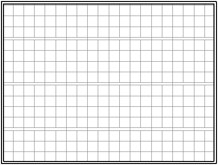
- In the Surface Pattern area of the Graphics tab, select the image tile to the right of where it says Pattern.

- In the Fill Patterns dialog, verify that the Pattern Type is set to Model. Then find and select the Fill Pattern created in Part 1.
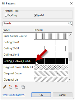
- Select the OK button to ratify the selection and dismiss the Fill Patterns dialog.
- In the Material Browser dialog, verify that the other settings on the Graphics tab are as desired. Assuming you want this ceiling pattern to appear the same one of the source Material (Acoustic Tile 24 x 24, or whatever Material you duplicated) (except for the Fill Pattern used), the settings should be correct.

- Select the OK button to add the new material to your project.


Part 3 will add the new Material to a Ceiling Type.
Subscribe to:
Posts (Atom)