January 28, 2006

Formatting Areas and Volumes in Schedules Using Drawing Setup

When displaying areas or volumes in a Schedule Table or a Schedule Tag, you could always apply a Property Data Format [login to the Triple D Design Wiki here, then copy this link and paste it into the Address line of the browser window viewing the Wiki for more about Property Data Formats] to get the desired precision and units suffix. And if those settings should always be the same, no matter what drawing an which project is open, then the Property Data Format is the way to go. You might also choose to set up fixed suffixes in a formula property, and could choose between imperial and metric by reading in the value of the MEASUREMENT System Variable, as noted in this blog article. But if you have different units needs in different projects [imperial for some, metric in others] or need to customize the precision or suffix text to suit the requirements of different clients, you would need to rework your Property Set Definition[s] for each unique case and apply a different Property Data Format to the area and volume properties.

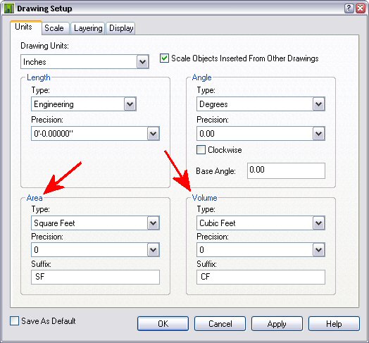
You may have noticed that the Units tab of the Drawing Setup dialog has a place to choose the Type, Precision and Suffix for both area and volume. ADT will report the area and volume values in an automatic property using the Type selected, but the Precision and Suffix are determined by the Property Data Format. You can, however, make use of the Precision and Suffix entries by using a formula property. You can read in these settings, then use a formula to apply the desired format. Special thanks go out to Tony Burba, for helping me find the right place to look for these properties in a thread in the Architectural Desktop Customization Discussion Group.


I have posted two sample files that were done in ADT 2006 to a thread in the Architectural Desktop Content Discussion Group. I chose a modular approach, with separate formulas for the Precision, Suffix and formatted value to display in a Schedule Table or Tag. If you prefer to limit the number of properties to make it easier for a user to find the manual ones when editing property data, you could just as easily have one formula for area and one for volume that read the desired precision and suffix values, storing them in variables, then using the variables to supply the values to the formatted RESULT. The formulas are in the AllObjects Property Set Definition, which is set up to apply to, strangely enough, all objects. The following discusses the properties used for the area value; the volume properties are similar.


The AreaUnformatted property is an automatic property that has the Area [or similar] property checked for all object types that have an area-type property available. I did this by checking the Area property under 3D Face, which will also check all of the other properties whose title is exactly "Area". Then I scrolled down the list and, while holding down the CTRL key, checked off other area-type properties for objects that did not have an "Area" property, such as "Base Area" for Area objects. A Property Data Format called "Standard-8" is applied to this property. Standard-8 is a copy of the out-of-the-box Standard Property Data Format, with the precision set to eight decimal places to get the maximum number of decimal places passed on the the formatting formula.

The AreaPrecision property is a formula property that reads the value set for precision on the Units tab of the Drawing Setup dialog, using the following formula:
Set acadApp = GetObject(,"AutoCAD.Application.16.2")
Set adtApp = acadApp.GetInterfaceObject("AecX.AecArchBaseApplication.4.7")
RESULT = adtApp.ActiveDocument.Preferences.AreaPrecision


Thanks also go out to Jimmy Bergmark for the tip on how to show long lines of code, posted to his JTB World blog.

The formula for the AreaSuffix property is similar to the AreaPrecision property formula, with a change to the referenced item:
Set acadApp = GetObject(,"AutoCAD.Application.16.2")
Set adtApp = acadApp.GetInterfaceObject("AecX.AecArchBaseApplication.4.7")
RESULT = adtApp.ActiveDocument.Preferences.AreaSuffix


The AreaFormatted property is the formula property that pulls it all together. The VBScript FormatNumber function is used to apply the desired precision and covert the number to a string to which the AreaSuffix value is concatenated.
FormatNumber([AreaUnformatted], [AreaPrecision], -1, 0, 0) & "[AreaSuffix]"


The application references shown above and in the sample file will work for ADT 2006 only. You can use these formulas in ADT 2004 or 2005 by changing the numbers as follows:
16.2 in 2006 becomes 16.1 in 2005 or 16 in 2004.
4.7 in 2006 becomes 4.5 in 2005 or 4 in 2004.

I also tossed in a ObjectType automatic property to have something in the sample Schedule Tables to link the sample object to the listed areas and volumes. In a real schedule, you probably have a identifcation number or some other means of showing what object is referenced on a given line and would not need this property.

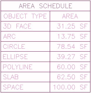
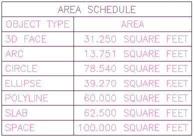
If you open the imperial units sample file, you will find the Units settings match those in the image above, and the Area Schedule looks like this:


Now change the settings for area units on the Units tab of the Drawing Setup dialog. I chose to use the settings shown below.


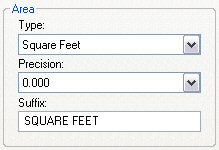
Update the Schedule Table, and you will find that the precision and units of the area values have changed according to your revised settings. For the example above, the Area Schedule now looks like this:


The AecArchBaseDatabasePreferences object gives access to a number of ADT settings. You can see the full listing in the Help. In 2006, expand the following on the Contents tab:
Architectural Desktop 2006 Help
>Architectural Desktop ActiveX Reference
>>AEC Architectural Automation Reference
>>>Objects
and then select the AecArchBaseDatabasePreferences Object.

There are quite a few settings in there that could be useful in a formula property for other scheduling "opportunities". If you hit upon a good one, be sure to share it with the community by posting a sample file in the Autodesk Architectural Desktop Content Discussion Group.

January 25, 2006

Using System Variable Values in Formula Properties

Have you ever wished you could check the value of an AutoCAD System Variable in a Formula Property? A post in the Autodesk Architectural Desktop 2006 Discussion Group asked if it were possible to set up a conditional Property Data Format that would change the suffix appended to a number, based on the units settings in a drawing. So far as I am aware, that is not possible, but it certainly would be nice to be able to do so.

It occurred to me that if I could read in the value of the MEASUREMENT System Variable, which is set to 0 for imperial units and 1 for metric units, I could then test that value and append the appropriate suffix value in a formula property.

One of the members of the ADT Development team - my apologies, as I do not know to whom to give the credit - had created a formula property for a Door that would read the fire rating property of the Wall to which the Door was anchored. You can get a sample file with that formula, written for ADT 2005, here and read additional discussion on that code here. Starting with that code and hacking my way through the VBA Help, I came up with the following. There are different versions for different ADT releases because the AutoCAD application number changes with each release:

For 2004:
Set app = GetObject(,"AutoCAD.Application.16")
RESULT = app.ActiveDocument.GetVariable("Measurement")


For 2005:
Set app = GetObject(,"AutoCAD.Application.16.1")
RESULT = app.ActiveDocument.GetVariable("Measurement")

For 2006:
Set app = GetObject(,"AutoCAD.Application.16.2")
RESULT = app.ActiveDocument.GetVariable("Measurement")


Note that in the actual formula,
RESULT = app.ActiveDocument.GetVariable("Measurement")
is all on one line; it appears on two lines here due to the format of the blog. Substitute the name of any other variable for "Measurement" to get that variable's value. The code above is set up to create a formula property that returns the value of the desired System Variable, and could then be referenced by another formula property. If you only need the value in one formula, you could add the code to the beginning of a formula, replacing RESULT with a variable name which could then be referenced in a conditional statement. For example, in an ADT 2006 drawing, if you had a Property Set Definition that included an automatic property called MyArea that held an unformatted area value, the following would append either " SF" or " m2" to the value in MyArea:

Set app = GetObject(,"AutoCAD.Application.16.2")
unitsType = app.ActiveDocument.GetVariable
("Measurement")
If unitsType = 0 Then
RESULT = "[MyArea]" & " SF"
Else
RESULT = "[MyArea]" & " m2"
End If
I attached a sample file, written for ADT 2004, to the previously mentioned thread in the ADT 2006 Discussion Group that demonstrates how this might be used. In that file, I took a "modular" approach, and have separate formulas to retrieve the MEASUREMENT value, set a suffix string and concatenate the final result. There is a sample Schedule Table showing the results, and if you change the value of MEASUREMENT and then update the Schedule Table, you will see the suffix change between " SF" and " m2".

Measurement = 0


Measurement = 1


An even cleverer method for the specific issue of area suffixes [or volume suffixes] would be to retrieve the dictionary values of the suffix as set on the Units tab of the Drawing Setup dialog. I am not certain that is possible and I will have to leave chasing that down for another day.

January 20, 2006

ADT Scheduling Class Materials Available


In April of 2005, I offered a class through the AUGI Training Program on Scheduling in ADT. The class materials were available for three months after the class concluded. AUGI has changed their archiving policy, and the materials are now available again, here. There is also a link to the class forum that was active while the class was being offered. You may want to look through it and see what discussion took place; there are also some additional example files scattered in the various threads and a "bonus" tutorial on Formula Properties in the "Formula Property Exercise" thread.

The website states that course materials will be available for three months, starting from six months after the conclusion of a course, but materials from January through June, 2005, are currently available. I do not know when older course materials will be removed, so if you are interested, download the materials soon. You do need to become a member of AUGI if you are not already a member in order to have access to the class materials, but membership is free.

If you join, be sure to take advantage of the class currently being offered by John Herridge on "Using Detail Components and Keynoting Effectively" - ATP103. You can register for the course by selecting the Current AUGI Training Program (ATP) Courses link on the AUGI Home page, or by selecting the Education link on the AUGI website, then selecting the AUGI Training Program Link at the left side, and then Current ATP Courses below that.

January 19, 2006

Half-inch GWB on Stud Wall Style

The out-of-the-box imperial walls styles use 5/8" GWB. That works fine for me, as that is my office's standard. If you want to use 1/2" GWB, you can easily make your own styles by using the following procedure. The example starts with a 3 1/2" stud, but you can apply the principles to any of the stud styles. Styles with multiple layers of GWB will require that the endcap polylines of several components be modified.

  1. Using the Style Manager or the Content Browser, bring the Stud-3.5 GWB-0.625 Each Side Wall Style into a new drawing. In the Style Manager [Walls category, under Architectural objects], edit the wall style.

  2. On the General tab, rename the style to Stud-3.5 GWB-0.5 Each Side. Edit the description to indicate 1/2" GWB.

  3. On the Components tab, change the width of the GWB components [numbers 1 and 3] to 1/2". Change the edge offset of Component 3 to -4". OK out to your drawing.

  4. Draw a "vertical" segment of the wall using the new style, from a point [say 0,0,0] to "@0,60". Zoom in on the upper end and note the gap in the endcap. This is because the endcap is was designed for 5/8" GWB, so ADT is scaling the endcap components down to make it fit 1/2" GWB, and that shortens up the part that is reaching across the stud.

  5. Still zoomed in, select the wall, right click and choose Endcaps > Edit In Place from the context menu. Select a point near the top end. If the left GWB component endcap polyline is highlighted, proceed, otherwise, hit Esc to deselect the right GWB component endcap polyline and select the left one. Grip edit the right end and stretch it to the right until it touches the left side of the right polyline. Click on the Save All Changes button of the In-Place Edit toolbar to save you changes.

  6. Open the Style Manager. In the Wall Endcap Styles category, rename the Stud-3.5 GWB-0.625 Each Side (End 1) style to Stud-3.5 GWB-0.5 Each Side (End 1), as you have changed the style to work with 1/2" GWB. Finally, in the Wall Opening Endcap Styles category, rename the Stud-3.5 GWB-0.625 Each Side (End 1)(2-Sided) style to Stud-3.5 GWB-0.5 Each Side (End 1)(2-Sided).

Now you can copy the modified wall style back to a source file [whether the out-of-the-box source file or one of your own, to make tracking your custom styles easier] and create a Tool palette tool from the new style. If you need to do this for many wall styles, you can save some time and rename the Wall Endcap Style at the same time you edit the Wall Style.

January 15, 2006

Door/Window Assembly Frame Depth in Window Schedule


In a thread in the Autodesk Architectural Desktop 2005 Discussion Group, I have posted a sample file that shows how both Windows and Door/Window Assemblies can be included in the same Schedule Table and have a Frame Depth column report values for both, even though Door/Window Assemblies do not have an automatic Frame Depth property. The example uses a style-based manual property to hold the Frame Depth value for the Door/Window Assemblies, and includes a formula property to pass through the appropriate value, depending upon the object type, so that one column can include the automatic property for Windows and the manual property for Door/Window Assemblies.

The thread includes a fairly extensive explanation of the properties I added to the out-of-the-box FrameStyles Property Set Defintion, so I will not repeat the explanation here. Be sure to download the DWADepthInSchedule2.zip attachment from my later post to get the revised Schedule Table that includes the manual DWAFrameDepthUnformatted property.

The sample file also makes use of a custom Classification Defintion called WindowSchedule, which is used to designate which Window and Door/Window Assembly styles are to be included or excluded in the test Window Schedule I added to show the results. By setting the Casement - Frameless Window Style to "NoSchedule", this style, used as an infill for the Door/Window Assemblies, is automatically filtered out of any selection set used for the Schedule Table.

January 14, 2006

Richard Binning: Auto Tagging With VBA

There have been many requests on the Autodesk Architectural Desktop Discussion Groups to have tags "built-in" to various objects, rather than having to add a tag after creating the object. The Space Auto Generate Tool, which runs the _AecSpaceAutoGenerate command, does offer the option of automatically tagging the spaces created by that command, but for other objects, like doors, you need to add the tag as a separate step.


For the past three months, Richard Binning has been graciously sharing his extensive knowledge of VBA customization in a series of articles titled "VBA Shortcuts in ADT" in AUGI Hot News that explain how you can create a VBA customization that will automatically tag a door after it is added to your drawing. If this is something you have always wanted to be able to do, or have been waiting for just the right occasion to improve your VBA skills, then I would encourage you to take a look at these articles:

November, 2005 - Part 1
December, 2005 - Part 2
January, 2006 - Part 3

Thanks to Richard for your generosity, and here is hoping that I can find the time to work through these articles myself. If you have not done so already, you will need to become a member of AUGI to access the articles above, but membership is FREE, and provides access to all of the other services offered by AUGI. Sign up now by going here.

Sorting Character Strings Like Numbers Image

Here is an image of the test schedule from the sample file referred to in the Sorting Character Strings Like Numbers article. For some reason I was unable to upload the image when I posted the original file. You can click on the image to see a larger version. Or just go to the Autodesk Architectural Desktop 2006 Discussion Group thread and download the sample file and check it out for yourself.

January 12, 2006

Sorting Character Strings Like Numbers

A question came up in a thread in the Autodesk Architectural Desktop 2006 Discussion Group regarding the sorting of a window schedule where the column to be sorted uses an Auto Increment - Character manual property type. The problem is that the column sorting treats the values as text string, and if you have more than 26 items, "AA" will be sorted between "A" and "B", rather than after "Z".

You could simply start your first value with the maximum number of characters needed to label all of the windows, for example, starting with "AAA" would allow you to have up to 17,576 windows before "AAAA" would appear between "AAA" and "AAB". You could also add another manual property to handle the sorting, but that would defeat the purpose of using an Auto Increment manual property type.

Formula properties to the rescue! I suggested that if padding the string was not acceptable, a formula property could be used to convert the character string to an integer value that could then be included in the schedule as a hidden column, with the sorting based on the numerical column. It is one thing to suggest doing so, and another altogether to write a formula that can do it, so I followed up with a sample file that demonstrates that such a formula can be written. Here is what I did in my sample file. The file was created in ADT 2004.

  1. I imported the out-of-the-box WindowObjects Property Set Definition and modified the Number property, changing its Type to Auto Increment - Character, its Default value to "A" [without the quotation marks] and its Format to "Case - Upper". I did this so I could use the out-of-the-box window tag without need for modification. I would recommend giving anything that you customize from the out-of-the-box content a different name, to avoid the potential for conflict when files already have the out-of-the-box version. You may have to modify copies of other content to coordinate with your renamed content, but in the long run that extra work will pay off, particularly when migrating to future releases.

  2. I created a new Property Set Defintion, WindowObjects2 to hold the formula property which will convert the character string in the WindowObjects:Number property to a number that can be sorted. There is no need for this to be in a separate Property Set Definition; it could just as easily been in the WindowObjects Property Set Defintion. If I had used a renamed copy of the WindowObjects definition for the changed Number property, I most likely would have included the formula in that definition as well. For the purposes of this example, separating it out here makes it easier to find it both in the Style Manager and the Properties palette and to minimize the changes in WindowObjects.

  3. The CharToNumber formula looks something like the following.

    strID = UCase("[WindowObjects:Number]")
    iLengthString = Len(strID)
    iTotal = 0

    For iCount = 1 to iLengthString
    iTotal = iTotal + (Asc(Right(strID, 1))
    * (10^(2*(iCount - 1))))
    strID = Left(strID, (iLengthString - iCount))
    Next

    RESULT = iTotal

    • Note that the iTotal line in the For Next loop is shown here on two lines, to fit the blog format, but appears on one line in the actual formula.

    • strID is a variable that is initially assigned the value of the WindowObjects:Number property, converted to upper case by the VBScript UCase function. As always, remember that you must select properties referenced by your formula from the lower panel [lower left panel in 2006], you can not simply type or cut-and-paste the name into the formula. Also be certain to enclose the property reference in double quotes so that the value is interpreted as a string, or the UCase function will fail.

    • iLengthString holds an integer indicating the initial number of characters in strID, as returned by the VBScript Len function.

    • iTotal holds the value that will be used for sorting the schedule, and is initialized at 0.

    • A For Next looping construct is used to process the string and calculate the final number to be returned. The loop is run once for every character in the strID string. The value of iCount is automatically incremented by the For Next construct on each pass.

    • Two things are done on each pass of the loop. A value based on the ASCII character code for the rightmost character, obtained using the VBScript Asc function, is added to the previous value in iTotal. The rightmost character is then stripped from the string in strID, and the loop repeats while additional characters remain.

    • Initially I was going to treat the characters just like decimal numbers, so that the rightmost character position would be the "ones" position, the one to the left of that the "tens" position, etc. Since the decimal values of the ASCII codes for capital letters in the English each have two digits, I chose to avoid any sorting problems caused by adding the overlapping positions by treating the left position as "ones", the next as "hundreds", the next as "ten thousands", etc. The (10^(2*(iCount - 1))) part of the formula provides the factor that accomplishes this. "^" is the exponentiation operator in VBScript. If you need to sort lower case letters differently from upper case letters or have any other characters above ASCII 99 in your string, you can allow three digits for each character by using a "3" instead of a "2" in that part of the formula: (10^(3*(iCount - 1)))

    • The RESULT line returns the final value of iTotal as the value of the formula.


  4. I set up some test windows, tagged them with the out-of-the-box window tag to add the WindowObjects Property Set and then manually added the WindowObjects2 Property Set by selecting all of the windows using QSelect and using the "Add property sets" button in the lower left corner of the Extended Data tab of the Properties palette. I edited the values of some of the number properties so that there would be some three-character values to include in the sort.

  5. I created a Schedule Table Style, WindowSortingTestSchedule, to display the WindowObjects:Number property as well as the WindowObjects2:CharToNumber property, with the schedule sorting on the latter column. I left the WindowObjects2:CharToNumber column visible in my test schedule so I could see the calculated value; in a "finished" Schedule Table Style, I would modify that column and make it hidden.

Download the sample file from the Autodesk Architectural Desktop 2006 Discussion Group, to see that the windows are sorted, based on the character values assigned to the WindowObjects:Number property, but in "numerical" style, starting from the right character, rather than alphbetically, starting with the left character.

January 11, 2006

AUGI CAD Matinees


In addition to CAD Camps - single-day events designed to provide an Autodesk-University-like training experience, AUGI is also organizing a series of CAD "Matinees", half-day events to provide access to training while minimizing time away from the office.

There is currently one CAD Matinee listed, on February 2, 2006, in St Paul/Minneapolis, MN. Registration for that matinee is open.

January 04, 2006

Residential Door Tags

If you are looking for an imperial units, residential-style door tag that displays the opening width and height for a 3'-0" x 7'-0" door as 3070, check out the sample content files posted to the Autodesk Architectural Desktop Content Discussion Group.

Sample by John Janzen.

Samples by Matt Dillon and David Koch.

Download the attachments from my 12/01/2005 reposts to assure getting uncorrupted downloads.


UPDATE 04/19/2014: The Content Discussion Group has been discontinued due to low activity, brought on, in part, when they allowed attachments in all of the groups. I looked through my archives, and was unable to find a copy of the John Janzen tag, but I was able to post a ZIP file that contains the residential style door tags that Matt Dillon and I had posted to this thread in the Autodesk Architectural Desktop 2007 & Prior Discussion Group.

January 01, 2006

AUGI CAD Camps - Early 2006

The dates and locations for the first AUGI CAD Camps have been posted at the CAD Camp website.

Omaha, Nebraska -- February 21
Seattle, Washington -- February 23
San Francisco Bay Area, California -- March 7
Houston, Texas -- March 9
Indianapolis, Indiana -- March 21

Registration for the Omaha event is currently open.