The NDA on discussing the features in the soon-to-be-released AutoCAD® Architecture 2011 has been lifted, and once again I find myself very busy (a good thing!). I will try to summarize the new features and improvements in this post, with the hope that I will find some time to put together some future posts with more detail (and screen captures) on some of the significant items.
User Interface
The good news (for some) is that there are no radical changes to the User Interface in 2011. There are some tweaks to the ribbons and the panels and tools thereon (to support added features, add user-requested editing tools to contextual ribbon tabs, etc.), but the basic setup remains as it was in 2010. Toolbars and pull-down menus have not been restored to the out-of-the-box CUIX files (other than the Express Tools pulldown, if you install the Express Tools).
One nice addition is that the View Cube is now available in 2D Wireframe. One consequence of that is that the grid in 2D Wireframe is now like the grids in the other visual styles – a grid of lines, rather than the old dots. I found the grid change somewhat annoying, but like having the View Cube available in 2D Wireframe, so I am willing to live with the grid (which I have generally turned off).
One new interface item is the Navigation Bar, a floating “mini palette” (I hesitate to use the term toolbar) that provides quick access to navigation commands like the steering wheels, pan, zoom and orbit. You can turn this on or off; when on, you can choose to have it free-floating or tie its position to the view cube.
There is also a minor change to the options for displaying the ribbon. You can now minimize to “panel buttons”. This is similar to the previously available minimize to panel titles, but provides a graphic icon along with the panel title. A dropdown menu has been added to the “cycle” button located at the right of the ribbon tab names, which allows you to directly pick a ribbon display state, rather than having to cycle through to the one you want.
Wall Cleanup
The Wall cleanup improvements that have been introduced in the past two releases are now “completed” with the 2011 release. While editing Wall cleanup “in place,” you now have access to Fillet and Chamfer tools to aid in creating the cleanup condition you need. (These had been previously added to the Wall Endcap edit-in-place feature.)
When using the in-place-editing feature, the Add/Remove Vertex option now displays a dynamic preview of the result should you click at the current cursor location. If you edit a Wall cleanup from an isometric view, the cleanup height is now dynamically displayed.
The “L” and “T” cleanup commands have been combined into the new “intelligent cleanup” command. You can use the intelligent cleanup command in much the same way as you previously used the “L” and “T” cleanups, or, if you have a large number of poorly drawn Walls, you can select them all and “intelligent cleanup” will go to work and do its best to clean them all up in one step, including the adjustment of cleanup radii when necessary.
I generally try to avoid non-zero cleanup radii whenever possible, but for those occasions where one must be set, if you do so by grip editing (with justification line display toggled on), a dynamic preview of the cleaned up condition (just component lines, no hatches) will display within the cleanup circle.
Constraints
A limited number of AutoCAD Architecture objects can now be used with the constraints feature that was added to AutoCAD in the 2010 release. You can apply constraints to Walls, Column Grids, Columns, Beams, Curtain Walls, Multi-View Blocks and Mass Elements. For example, a Wall can be constrained to a Grid line, so that it always remains a fixed distance from the Grid line, or two Walls, such as the opposite Walls of a corridor, can be constrained to remain a fixed distance apart.
Renovation
First included in a subscription extension for 2010, the Renovation feature is now integrated into the shipping product. The renovation feature is intended to make renovation projects done with AutoCAD Architecture easier for the user. While I have not had an opportunity to try this feature under real-world-project conditions, it does appear to be worth investigating. It makes use of the AutoCAD Architecture Display System, layers and object visibility, using rules and settings that you can customize, to allow the user to transform objects between new, existing-to-remain and existing-to-be-demolished. Once you have things set up, a click of a ribbon tool is all that is needed to toggle between a demolition plan display and a new work plan display. Any objects already drawing when renovation mode is activated become “existing” objects. If you demolish an existing Door, not only does the Door get transformed to "demolition", but the hole in the Wall will be filled with one or more Mass Elements (one per visible component) that will be visible as "new" infill when the new work drawing is displayed.
For those using the US National CAD Standard layering, it appears to work best if your “new work” layers do NOT have a status field (“-N”) specified, which would be something of a deal breaker for my office, as we do use the “-N” status field on our new work layers to make managing new work layers easier.
Demolished items can be easily excluded from Schedule Tables by setting a new property added to Schedule Tables on the Design tab of the Properties palette.
Enhanced Custom Grid
Also part of the 2010 subscription extension, the Enhanced Custom Grid allows you to create column grids where at least one column line does not run all the way across the entire building as a single object that can have column bubble tags added all at once and which supports primary and secondary levels of column line numbering (for example: 1, 1.3, 1.5, 2, 3, 4, 4.2, 4.7, 4.9, 5). This should reduce the need for converting linework and avoid the tedium of having to tag each column line of a linework-converted grid individually.
Custom Column
The Custom Column tool, from the 2010 subscription extension, provides a quick way to transform a closed shape (closed polyline, spline, ellipse, or circle) into a structural member shape, structural member style and an instance of that style in a few, easy steps. If you do not need the separate graphics for low, medium and high detail that using the MemberShape command affords, this is a great way to create a custom column shape that is not available through either the Structural Member Catalog or the Structural Member Wizard.
Placement of Openings in Walls
Yet another 2010 subscription extension item, the placement of openings in Walls (Doors, Door/Window Assemblies, Windows and Openings) has been enhanced. You can now place multiple, evenly spaced objects in one operation, and the boundaries of the spacing can now include grid lines, in addition to intersecting Walls. One consequence of this is that Center and Offset are now two separate placement modes, rather than one combined Center/Offset mode.
Miscellaneous
Structural Member Placement
When placing a Structural member that is not related to other, already existing objects, in previous releases you had to use the CTRL toggle to get to a state in which you can specify exact endpoints. In 2011, this process is greatly simplified by adding an “On object” property to the Design tab of the Properties palette, under the General category (only at the time of object placement).
Drawing Management and Windows Explorer
The Project Browser and Project Navigator dialogs can now interact with Windows Explorer. Files can be sent to the Recycle Bin (DELETE key) or permanently deleted (SHIFT+DELETE) from the Project Navigator palette. Windows Explorer can be opened directly to a project folder, category folder or single drawing by right-clicking and choosing “Show in Windows Explorer from the context menu.
IFC
A number of IFC Enhancements have been made. I have not had to use IFC to date, so I will leave the explanation of what has been added to others who have.
Web-based Help
The Help is now Web-based. If you have a live Internet connection, you will access the Help via the Autodesk website, giving you access to more frequent updates and improved search ability. This is also claimed to be the first step in providing AutoCAD Architecture help that is better integrated with the AutoCAD help. A toggle on the System tab of the Options dialog allows you to disable the over-the-Internet help, in which case a local version is used. The local version is still viewed and searched through a web browser window, however.
AutoCAD Improvements
Selection Cycling
When you click on overlapping objects, you now get a selection dialog listing all of the objects beneath the pick point, from which you can choose the one you want (or none). As you pass your cursor over the list of objects in the dialog, the object associated with the item under your cursor highlights to aid in determining which object you want. I found this quite handy.
”Borrowed” from AutoCAD Architecture
A number of “new” AutoCAD features will be familiar to AutoCAD Architecture users: Isolate Objects, Select Similar and Add Selected have made their way into the main AutoCAD product.
Polyline Grip Editing
New midpoint grips have been added, and all grips offer right click editing options, similar to what AutoCAD Architecture users have had when editing various AEC objects.
Transparency
Transparency has been added as a property that can be applied to layers and objects in the same way that color, linetype, lineweight and plot style have previously been applied. A toggle button has been added to the application status bar to toggle transparency on and off. While that toggle does not affect plotting, the Plot and Page Setup dialogs now have a checkbox for enabling/disabling transparency when plotting. Note that for AEC objects, transparency has not been added to the display settings of components, the General Properties tab of the Object Display dialog or on the Design or Display tabs of the Properties palette. You can, however, assign transparency to an AEC object’s layer. New AutoCAD features often take an extra release to work their way to AEC objects, so perhaps this will show up in 2012 or 2013.
Hatching
Hatch Creation and Hatch Editor contextual ribbon tabs avoid the need for a dialog box to display when using the Hatch tool or editing an existing hatch. When using the pick points method, as you move your cursor, a preview of the hatch that would be created if you clicked at the current cursor location is displayed.
There are many other AutoCAD changes that will, no doubt, be covered in greater detail by others; those are just a few that caught my eye.
March 25, 2010
March 10, 2010
AutoCAD® Architecture 2010 - UI Changes, Part 8 - The Ribbon, Manage Tab
Manage Tab
The Manage tab is the sixth static (always available) tab provided in the out-of-the-box ACA CUI. The image below and all screen captures in this article are based on the shipping version.
Navigate Panel
The Action Recorder Panel contains commands related to using the Action Recorder to save, edit and play back command sequences.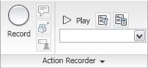 The Record command button starts the Action Recorder (ACTRECORD command). The Insert message command button allows you to insert a message in the Action tree, which will then be displayed during playback (ACTUSERMESSAGE command). The Insert Base Point command button is used to establish a point using absolute coordinates, for use by the prompts that follow in the macro (ACTBASEPOINT command). The Pause for User Input command button allows you to insert a request for user input in the macro (ACTUSERINPUT command). The Play command button plays back the macro selected in the Action Macro drop-down list. The Preference command button allows you to determine the behavior of the Action Recorder panel during recording and playback as well as indicate whether or not you want to be prompted for a macro name when recording is stopped. The Manage Action Macros command button allows you to copy, rename, modify or delete action macro files (ACTMANAGER). The Available Action Macro drop-down list allows you to choose from a list of available macros. The chosen macro is available for playback and is displayed in the Action Tree. The ACTMANAGER command can also be launched from the last item on the list.
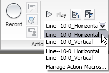 Click on the Action Recorder title bar to expand the panel and reveal the action tree. The contents of the macro chosen on the drop-down list will be displayed in the Action Tree.
CAD Standards Panel
The CAD Standards Panel contains commands related to the AutoCAD® CAD Standards feature.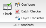 The Check command button runs the CHECKSTANDARDS command to check the current drawing for standards violations. The Configure command button allows you to associate the current drawing with one or more standards files (STANDARDS command). The Batch Checker command button allows you to specify one or more drawings to be checked (BATCHSTANDARDSCHECKER command). The Layer Translator command button runs the LAYTRANS command, allowing you to map the layers in the current drawing to layer names and properties in another drawing file or in a standards file, and then convert the layers in the current drawing based on that mapping.
Project Standards Panel
The Project Standards Panel contains commands related to the AutoCAD Architecture Project Standards feature. You must be working in an AutoCAD Architecture project (using Project Browser and Project Navigator) in order to make use of these tools.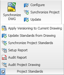 The Synchronize DWG command button will update the current drawing using the styles and settings defined in the project standards drawing(s) for the current project (SYNCHRONIZEPROJECTDRAWING command). The Configure command button allows you to indicate the project standards with which the current drawing will synchronize (PROJECTSTANDARDS command). The Synchronize Project command button runs the SYNCHRONIZEPROJECT command, which will synchronize all of the drawings in a project to the styles and settings in the project standards drawing(s). The Update command button will update the project standards check file (AutoCAD standards) for each file in the project. Select the Project Standards title bar to expand the panel and reveal additional command buttons related to Project Standards: Apply Versioning to Current Drawing (VERSIONMODIFIEDOBJECTS), Update Standards from Drawing (UPDATESTANDARDS), Synchronize Project Standards (SYNCHRONIZESTANDARDS), Setup Report (PROJECTSTANDARDSSETUPREPORT), Audit Report (AUDITPROJECT) and Audit Project Drawing (AUDITPROJECTDRAWING).
Style & Display Panel
The Style & Display Panel offers commands related to AutoCAD Architecture styles and display system.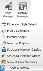 The Style Manager command button opens the Style Manager, allowing you to create, edit and/or delete styles and definitions (STYLEMANAGER). The Display Manager command button opens the Display Manager, so that you can create and/or edit drawing default settings for Display Representations, create and/or edit Display Representation Sets and create and/or edit Display Configurations (DISPLAYMANAGER). Click on the Style & Display title bar to expand the panel and reveal seven additional command buttons. The Dimension Style Wizard command button opens the AEC Dimension Display Wizard, allowing you to change the display properties of AEC Dimension Styles (DIMWIZARD). The Profile Definitions command button opens the Style Manager, filtered for Profile Definitions (PROFILEDEFINE). The Member Shape command button opens the Insert Member Shapes dialog, which allows you to insert one of the structural member shapes defined in the drawing (MEMBERSHAPEINSERT). The Insert as Polyline command button allows you to insert a profile defined in the current drawing as a polyline (PROFILEASPOLYLINE). The Structural Member Catalog command button opens the Structural Member Catalog dialog, which allows you to create Structural Member Styles (and the associated Structural Member Shapes) from a listing of predefined, industry-standard shapes (MEMBERCATALOG). The Structural Member Wizard command button opens the Structural Member Style Wizard dialog, which allows you to create Structural Member Styles based on user-input dimensions for a variety of basic shapes (MEMBERSTYLEWIZARD). The Show Display Overrides command button (SHOWDISPLAYOVERRIDES) allows you to easily identify objects that have an object-level display override by highlighting and/or listing them.
Applications Panel
The Applications Panel has commands related to custom applications that can be run in AutoCAD Architecture, such as AutoLISP or VBA routines.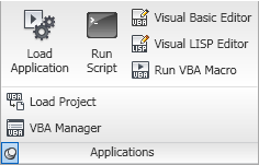 The Load Application command button runs the APPLOAD command, allowing you to load and unload custom applications and to add customizations to the Startup Suite, which will then be loaded each time you start AutoCAD Architecture. The Run Script command button allows you to execute script file (SCRIPT command). The Visual Basic Editor command button displays the Visual Basic Editor, allowing you to edit VBA projects (VBAIDE). The Visual LISP Editor command button runs the VLISP command, calling up the Visual LISP Integrated Development Environment window, where you can create and edit LISP routines. The Run VBA Macro allows you to run, edit or delete a VBA macro (VBARUN). Click on the Applications title bar to expand the panel and reveal two additional command buttons: Load Project, to load a global VBA project into the current work session (VBALOAD) and VBA Manager, to manage your VBA projects in a dialog box (VBAMAN). Note that in the 2010 release, Microsoft® Visual Basic® for Applications software is not installed when AutoCAD Architecture is installed. You can download the files needed to use VBA in AutoCAD at http://www.autodesk.com/vba-download.
Customization Panel
The Customization Panel has commands related to customizing the AutoCAD Architecture user interface.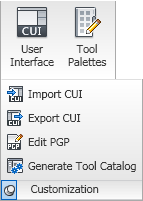 The User Interface command button opens the Customize User Interface dialog, which gives you full access to customizing most aspects of the user interface (CUI command). The Tool Palettes command button opens the Customize dialog, allowing you to customize the organization of tool palettes and tool palette groups, the one part of the interface not covered by the CUI dialog (Customize command). Click on the Customization title bar to expand the panel and reveal four additional command buttons. The Import CUI command button opens the Customize User Interface dialog, with the Transfer tab current, ready to transfer items from an enterprise or partial CUIX file to the main CUIX file (CUIIMPORT command). The Export CUI command button also opens the Customize User Interface dialog to the Transfer tab and allows you to export items from the main customization file to an enterprise or partial CUIX file (CUIEXPORT command). In fact, you can use either of those tools to move files between the main CUIX file and any other CUIX file you choose to open. The only difference is the Import CUI command button puts the main CUIX file on the right side, and the Export CUI command button puts the main CUIX file on the left side. The Edit PGP command button opens the first ACAD.pgp file found in the search path for editing (on my computer, in Notepad). The Generate Tool Catalog command button opens the Populate Tool Catalog from Content Drawings dialog, which allows you to create tools for selected ACA object types from a selected source file and place the tools in a new or existing tool catalog (AECTOOLCATALOGGENERATOR command). The tools can be created in Categories or in Palettes.
The Manage tab is the sixth static (always available) tab provided in the out-of-the-box ACA CUI. The image below and all screen captures in this article are based on the shipping version.

Navigate Panel
The Action Recorder Panel contains commands related to using the Action Recorder to save, edit and play back command sequences.
 The Record command button starts the Action Recorder (ACTRECORD command). The Insert message command button allows you to insert a message in the Action tree, which will then be displayed during playback (ACTUSERMESSAGE command). The Insert Base Point command button is used to establish a point using absolute coordinates, for use by the prompts that follow in the macro (ACTBASEPOINT command). The Pause for User Input command button allows you to insert a request for user input in the macro (ACTUSERINPUT command). The Play command button plays back the macro selected in the Action Macro drop-down list. The Preference command button allows you to determine the behavior of the Action Recorder panel during recording and playback as well as indicate whether or not you want to be prompted for a macro name when recording is stopped. The Manage Action Macros command button allows you to copy, rename, modify or delete action macro files (ACTMANAGER). The Available Action Macro drop-down list allows you to choose from a list of available macros. The chosen macro is available for playback and is displayed in the Action Tree. The ACTMANAGER command can also be launched from the last item on the list.
 Click on the Action Recorder title bar to expand the panel and reveal the action tree. The contents of the macro chosen on the drop-down list will be displayed in the Action Tree.
CAD Standards Panel
The CAD Standards Panel contains commands related to the AutoCAD® CAD Standards feature.
 The Check command button runs the CHECKSTANDARDS command to check the current drawing for standards violations. The Configure command button allows you to associate the current drawing with one or more standards files (STANDARDS command). The Batch Checker command button allows you to specify one or more drawings to be checked (BATCHSTANDARDSCHECKER command). The Layer Translator command button runs the LAYTRANS command, allowing you to map the layers in the current drawing to layer names and properties in another drawing file or in a standards file, and then convert the layers in the current drawing based on that mapping.
Project Standards Panel
The Project Standards Panel contains commands related to the AutoCAD Architecture Project Standards feature. You must be working in an AutoCAD Architecture project (using Project Browser and Project Navigator) in order to make use of these tools.
 The Synchronize DWG command button will update the current drawing using the styles and settings defined in the project standards drawing(s) for the current project (SYNCHRONIZEPROJECTDRAWING command). The Configure command button allows you to indicate the project standards with which the current drawing will synchronize (PROJECTSTANDARDS command). The Synchronize Project command button runs the SYNCHRONIZEPROJECT command, which will synchronize all of the drawings in a project to the styles and settings in the project standards drawing(s). The Update command button will update the project standards check file (AutoCAD standards) for each file in the project. Select the Project Standards title bar to expand the panel and reveal additional command buttons related to Project Standards: Apply Versioning to Current Drawing (VERSIONMODIFIEDOBJECTS), Update Standards from Drawing (UPDATESTANDARDS), Synchronize Project Standards (SYNCHRONIZESTANDARDS), Setup Report (PROJECTSTANDARDSSETUPREPORT), Audit Report (AUDITPROJECT) and Audit Project Drawing (AUDITPROJECTDRAWING).
Style & Display Panel
The Style & Display Panel offers commands related to AutoCAD Architecture styles and display system.
 The Style Manager command button opens the Style Manager, allowing you to create, edit and/or delete styles and definitions (STYLEMANAGER). The Display Manager command button opens the Display Manager, so that you can create and/or edit drawing default settings for Display Representations, create and/or edit Display Representation Sets and create and/or edit Display Configurations (DISPLAYMANAGER). Click on the Style & Display title bar to expand the panel and reveal seven additional command buttons. The Dimension Style Wizard command button opens the AEC Dimension Display Wizard, allowing you to change the display properties of AEC Dimension Styles (DIMWIZARD). The Profile Definitions command button opens the Style Manager, filtered for Profile Definitions (PROFILEDEFINE). The Member Shape command button opens the Insert Member Shapes dialog, which allows you to insert one of the structural member shapes defined in the drawing (MEMBERSHAPEINSERT). The Insert as Polyline command button allows you to insert a profile defined in the current drawing as a polyline (PROFILEASPOLYLINE). The Structural Member Catalog command button opens the Structural Member Catalog dialog, which allows you to create Structural Member Styles (and the associated Structural Member Shapes) from a listing of predefined, industry-standard shapes (MEMBERCATALOG). The Structural Member Wizard command button opens the Structural Member Style Wizard dialog, which allows you to create Structural Member Styles based on user-input dimensions for a variety of basic shapes (MEMBERSTYLEWIZARD). The Show Display Overrides command button (SHOWDISPLAYOVERRIDES) allows you to easily identify objects that have an object-level display override by highlighting and/or listing them.
Applications Panel
The Applications Panel has commands related to custom applications that can be run in AutoCAD Architecture, such as AutoLISP or VBA routines.
 The Load Application command button runs the APPLOAD command, allowing you to load and unload custom applications and to add customizations to the Startup Suite, which will then be loaded each time you start AutoCAD Architecture. The Run Script command button allows you to execute script file (SCRIPT command). The Visual Basic Editor command button displays the Visual Basic Editor, allowing you to edit VBA projects (VBAIDE). The Visual LISP Editor command button runs the VLISP command, calling up the Visual LISP Integrated Development Environment window, where you can create and edit LISP routines. The Run VBA Macro allows you to run, edit or delete a VBA macro (VBARUN). Click on the Applications title bar to expand the panel and reveal two additional command buttons: Load Project, to load a global VBA project into the current work session (VBALOAD) and VBA Manager, to manage your VBA projects in a dialog box (VBAMAN). Note that in the 2010 release, Microsoft® Visual Basic® for Applications software is not installed when AutoCAD Architecture is installed. You can download the files needed to use VBA in AutoCAD at http://www.autodesk.com/vba-download.
Customization Panel
The Customization Panel has commands related to customizing the AutoCAD Architecture user interface.
 The User Interface command button opens the Customize User Interface dialog, which gives you full access to customizing most aspects of the user interface (CUI command). The Tool Palettes command button opens the Customize dialog, allowing you to customize the organization of tool palettes and tool palette groups, the one part of the interface not covered by the CUI dialog (Customize command). Click on the Customization title bar to expand the panel and reveal four additional command buttons. The Import CUI command button opens the Customize User Interface dialog, with the Transfer tab current, ready to transfer items from an enterprise or partial CUIX file to the main CUIX file (CUIIMPORT command). The Export CUI command button also opens the Customize User Interface dialog to the Transfer tab and allows you to export items from the main customization file to an enterprise or partial CUIX file (CUIEXPORT command). In fact, you can use either of those tools to move files between the main CUIX file and any other CUIX file you choose to open. The only difference is the Import CUI command button puts the main CUIX file on the right side, and the Export CUI command button puts the main CUIX file on the left side. The Edit PGP command button opens the first ACAD.pgp file found in the search path for editing (on my computer, in Notepad). The Generate Tool Catalog command button opens the Populate Tool Catalog from Content Drawings dialog, which allows you to create tools for selected ACA object types from a selected source file and place the tools in a new or existing tool catalog (AECTOOLCATALOGGENERATOR command). The tools can be created in Categories or in Palettes.
Subscribe to:
Posts (Atom)