Previous Article in the Series: AutoCAD Architecture 2009 - Part 3
Drawing Management
There have been a number of improvements to the Drawing Management feature in the 2009 release. I do not use this feature at work, and while I have some limited experience with it, I can not pretend to be intimately familiar with it, particularly with regard to what features were added when. So bear with me as I try to convey the new features.
One item that I know has been on the wish list of many people for some time is the ability to make use of Project Browser and Project Navigator without first having to have a drawing file open. As you can see in the series of screen captures below (click on any image to see a full-size version, then use the Back button to return here), both can now be opened and used with no drawing file open.
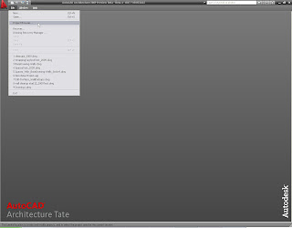
Project Browser... in the File Pulldown, Zero-Doc State
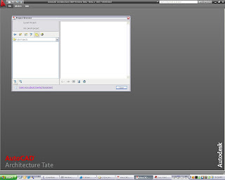
Project Browser Open, Zero-Doc State
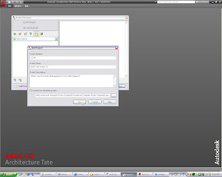
Adding a New Project, Zero-Doc State
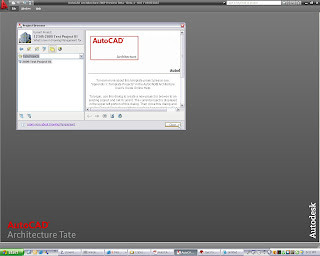
New Project Set Current, Zero Doc State
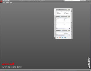
Project Navigator Open, Zero-Doc State
Here is another oft-wished for feature. There is now a button at the bottom of the Project tab of Project Navigator that will allow you to close the current project. Opening Project Browser is no longer necessary to close the current project. You will, however, need to use Project Browser to set a project current, as Project Navigator will close when the current project is closed.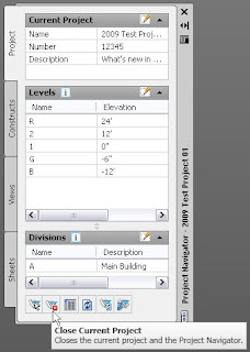
Close Current Project in Project Navigator
When closing or switching projects in 2009, you now have the option to close all project files from the project being closed.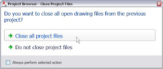
Close All Open Drawings in Closing Project
That might put you back in a zero-doc state, but that is not a problem in the 2009 release.Yet another item is removed from the wish list: you can now open a file "read-only" from Project Navigator.
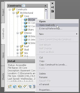
Open File Read-Only in Project Navigator
There are a number of other file-related enhancements in Project Navigator. Files that are open are now indicated graphically by the addition of a small lock in the lower right corner of the file icon. In the image below, the 00 Core, Stairs and 01 Interior Constructs are open, and show the lock icon. If you have multiple files from a project open, you are now given the opportunity to bring a particular file that is not current to the front on the right-click context menu in Project Navigator. You can also close an open file from that same context menu.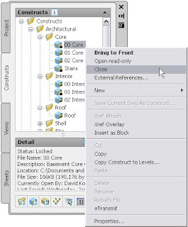
Right-click Menu Options for a Construct in Project Navigator
The External References Worksheet, accessed from that same right-click menu, has been enhanced in 2009. Instead of merely showing a list of the externally referenced files in a given Project Navigator file, you can now also see the saved path and found location for each of the external references.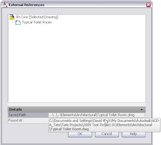
External References Worksheet
The Project Properties Worksheet has gotten a makeover, making it easier to find the particular item you want to edit. Of particular interest, note that the last item, Project Tool Palette Group, is set to None. Project Tool Palettes are now optional.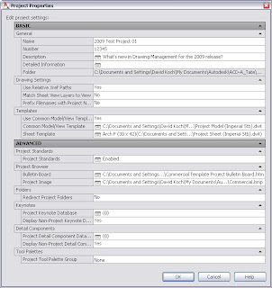
Project Properties Worksheet
Drawing tooltips in Project Navigator are now available, paralleling those available in the Sheet Set Manager in AutoCAD®. In Project Navigator, the tooltips are available for all files types, not just Sheets.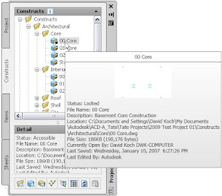
Drawing Tooltips in Project Navigator
The tooltips combine the information on the Detail and Preview options of the Detail area at the bottom of Project Navigator; you may find that you can close the Detail area, expanding the file viewing area, and using the tooltip when you need to see that information.There are a number of other Drawing Management enhancements. If these sound like a solution to one or more pain points for you, be sure to check them out in 2009:
- Double-click on APJ file enhancements.
- Commas in Sheet file names (and therefore sheet drawing titles).
- Who-has information
- Recovery from failed, cancelled or missed repathing.
- Reference file repathing queue worksheet.
- Use layout name for sheet name.
- Improvements to the Attach Elements to Constructs Worksheet
- Project Templates installation location improvements.
Additional Features
The context menu for external references has been improved, with the addition of several new options. You can now unload, reload, detatch or bind an external reference from the context menu.
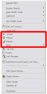
External Reference Right-Click Context Menu
Support for gbXML has been added to the 2009 release. Those of you interested in green building and extracting information from the building model will want to look into this more deeply. You can find an overview at the gbXML.org website.IFC import and export has been improved to provide greater control over the IFC process.
Material tools now allow you to apply a material directly to a component of an AEC object or to an AutoCAD object. When a tool is active, hovering over a component will highlight the component and give you a tooltip identifying the component and listing the material that would be applied. The tooltip will also let you know if the highlighted component can not accept a material. For AEC objects with styles, the assignment can be made at the style or object level.
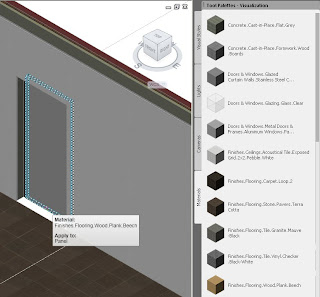
Applying a Material to a Door Panel with a Material Tool
Here is another one that many have asked for over the years - all dialogs in ACD-A 2009 are resizable. I have not personally opened every single one to see if this is true, but I do not recall any that could not be resized.The Match Properties command (MATCHPROP) now also allows you to copy the style of an AEC object to other objects of that type. Look for the new icon on the Standard toolbar.
Match Properties Icon
The Display tab of the Properties palette has also been improved. The "light bulb" icons on the components list that formerly only indicated whether or not the component was on or off can now be used to toggle the on/off status of the component.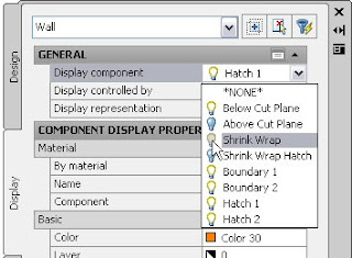
Toggle Component Visibility with Light Bulb Icon
All of the Display Properties of an object, including properties that appear on additional tabs like Cut Plane and Other in the Display Manager, are now available through the Display tab of the Properties palette.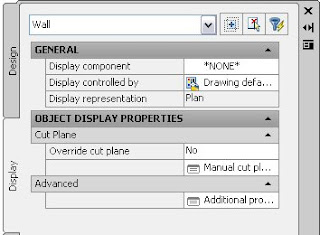
All Display Properties Accessible Through Display Tab
AutoCAD Features
There are also a number of improvements to AutoCAD 2009 that will also be available in ACD-A 2009. Many of these have been covered in detail by other bloggers of greater stature than I, and I will defer to their postings. If you have not already read these articles, you may want to take advantage of the following links.
General Overview
Heidi Hewett
Quick Access Toolbar
Lynn Allen
Heidi Hewett
Steering Wheel
Lynn Allen
ViewCube
Lynn Allen
ACD-A 2009 users will also see the ViewCube in the Object Viewer.
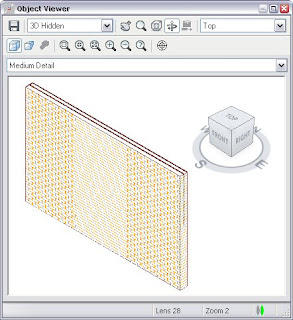 and the Components tab of a Wall Style, among other places.
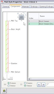
Action Recorder
Lynn Allen
Heidi Hewett
Show Motion
Lynn Allen
Quick Properties
Lynn Allen
Heidi Hewett
Quick View Layouts
Lynn Allen
Heidi Hewett
Shaan Hurley
Status Bar
Heidi Hewett
Menu Browser
Heidi Hewett
I hope this series on the new features in AutoCAD® Architecture 2009 has helped whet your appetite for the coming release and shown that there are features in the new release that make the effort to install it worthwhile.
