April 28, 2006

Stud Size Offset

3/5/2009 UPDATE: If you are using ACA 2010 or later, you can achieve the same results using Wall Cleanup Edit in Place.

In order to avoid finished surface offsets within a room, a change of stud sizes is often made at the intersection of a perpendicular wall. When this is not possible, and you end up with two wall styles that are identical except for the stud size, with one finished face aligned, you will end up with a cleanup error, as shown below (Low Detail on the left, High Detail on the right). The problem is that the finish materials on the offset side do not align, and ADT does not know how to resolve that.

You could apply a wall merge to resolve the cleanup issue, and the Low Detail graphics are acceptable, but the High Detail graphics are not, as seen below.

If you want to have the wall appear cleaned up and have the components align, with the finish material wrapping the end of the wider stud and aligning with the finish material on the narrower stud, you will have to resort to a little "trickery". The first thing you need to know is that you can create an "open" endcap for a wall, by giving the defining polyline a non-zero thickness at any segment you wish to be invisible. The second thing you need to know is that you can specify a negative offset on an endcap, which pushes the endcap graphics out beyond the end of the wall graph line. This allows you to get the appearance of having the two walls meet WITHOUT having the graphlines touch, which would trigger a cleanup attempt, which would fail - and prevent the endcaps from showing.

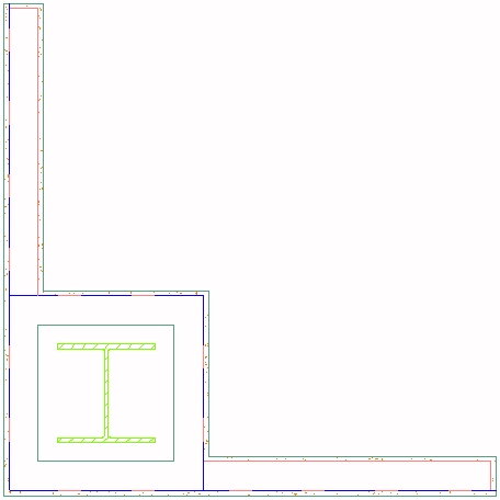
The image below shows the two walls, with the endcaps applied, but separated so you can see what each end is doing. The left viewport shows Low Detail, the right viewport shows High Detail. I separated the polylines that make up the endcaps so you can clearly see each line. The narrower partition has a simple, straight-line open endcap, where the polylines are single-segment with a non-zero width. The left polyline at the wider partition projects the finish material on the side that aligns by the thickness of the finish material; the end segment has a non-zero width. The stud component polyline offsets by the difference in stud size, then projects forward by the thickness of the finish material. The segment that abuts the narrower stud has a non-zero thickness. The finish material that offsets wraps around the stud offset; the end is composed of two segments; the left segment is the width of the finish material and has a non-zero thickness; the right segment length is the difference in stud sizes and has a zero width, so that you get a line at that portion.

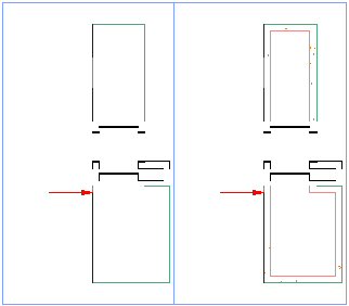
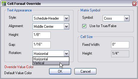
Simply drawing the polylines with the thickness of the finish material does NOT offset the endcap; if you use the Calculate Automatically option from the right-click context menu for walls, the graphline will initially extend to the end of the visible graphics. In the image above, the red arrow points to the end of the graphline, which is inset 5/8" from the end of the visible graphics. This was achieved by editing the Wall Endcap Style in the Style Manager after the endcap was created, and, on the Dimensions tab, setting a Return Offset value of -0.625", as shown below.

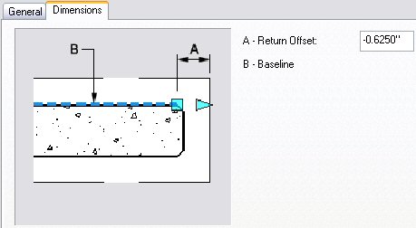
The final result can be seen below, with, as before, the Low Detail on the left and the High Detail on the right. Remember that the graphline of the narrower partition stops even with the finished face of the returning finish material; the graphline of the wider partition stops even with the end of the stud. The 5/8" gap keeps the walls from cleaning up, and the open endcaps make it look like they do clean up.

I initially tried doing the offset on the narrower partition, but got an undesirable result, as shown below. For some reason, the Shrink Wrap gets applied to the lateral offset of the narrower stud. This is particularly noticeable in Low Detail but is also present in the High Detail and would plot with the heavier Shrink Wrap lineweight. You can download a sample file that has the wall and endcap styles used to create the graphics in this article in the Cleanup at Stud Size Change thread in the Autodesk Architectural Desktop Wishes Discussion Group. Get the StudSizeOffset2.zip from my last post in that thread - Apr/27/06 - 23:34 (GMT) or 19:34 (EDT).

April 27, 2006

Stacking Properties in a Schedule Table

There is currently no ability to "stack" properties in an ADT Schedule Table, that is, to have a row where one column has one property on top of another property. But by using a Formula property, you can easily combine the values in two separate properties into one property, to be displayed in a single column. Toss in a line feed character, and you will get one property stacked on top of the other - without a dividing line, but hey, this is not Excel.

Here is an example for a Room Finish Schedule. You can get the source file that contains the formulas that generated the image below in the Split Cells in Schedule thread in the Autdesk Archtitectural Desktop Discussion Group. The formula for the "North Matl North Fin" column looks like this:

"[NorthMaterial]" & Chr(10) & "[NorthFinish]"

"[NorthMaterial]" and "[NorthFinish]" are property references. You MUST add property references by double clicking on them in the Property Definitions box [at the bottom of the Formula Property Definition dialog in 2004/2005] or the Insert Property Definitions box [at the bottom left of the Formula Property Definition dialog in 2006/2007]. Enclosing the reference in double quotation marks tells the formula to interpret the value in the NorthMaterial property as a string.

& is the concatenation operator. It tells VBScript to combine the string value in front of it with the one behind it into one string.

Chr (10) is a use of the VBScript Chr function, which takes a decimal number as an argument and returns the associated ASCII character. "10" is the ASCII character for a line feed, so this inserts a line feed character into the string, and is what causes the balance of the string to appear on a second line in the schedule table.

April 21, 2006

Wall "Bumpouts"

There are many ways to get a wall to "bumpout", whether for a column enclosure, a chase, or some other interruption. Each has its advantages and disadvantages, but my preferred way of dealing with this in metal stud and gypsum wallboard [GWB] construction is to have wall styles with GWB on only one side of the stud and "build" the bumpout just like it would be built in the real world.

This does add more walls to your drawing, including some short ones, but it offers great flexibility:
  • Draw the enclosure at any size.
  • Draw the enclosure in most any shape.
  • Position the enclosure anywhere along the length of a wall, including at the ends.
  • Edit the far ends of abutting walls without worrying whether the enclosure will be affected.
  • Edit the enclosure easily, on screen, without dialogs or in-place editing.
You can find the sample file that generated the image below in this thread in the Autodesk Architectural Desktop Discussion Group.

April 13, 2006

Matt Dillon on "Revit vs ADT"

And/or "ADT vs Revit". Read his thoughts here, and look forward to more insight from someone who uses and teaches both programs.

April 08, 2006

Enhanced Property Data Features in ADT 2007, Part 5

This post will cover the three improvements made to Schedule Tables.

  1. Table Title Overrides: In previous releases, the title for the schedule table specified on the Layout tab when editing a Schedule Table Style was the title used for all instances of that style. If you wanted otherwise identical schedules with different titles, such as "First Floor Door Schedule", "Second Floor Door Schedule", etc., you would have to copy the style for each unique title. ADT 2007 now provides for a table title override. The title specified in the Schedule Table Style is the initial title, but you can change it on the Properties palette, using the Title property in the General section, as shown in the image below.

  2. Header Overrides: In previous versions of ADT, the formatting overrides for headers was limited to making all headers of the same type [Column or Matrix] the same. In ADT 2007, you can still set global overrides on the Layout tab, but you can also override the formatting on each column individually. This is great if you have a column with "narrow" data but a "wide" header, you can now set the rotation of that single column to vertical, without affecting all of the other headers of the same type.
    Schedule Table Before Header Override


    Header Override Button in Modify Column Dialog


    Setting a Vertical Rotation


    Schedule Table After Header Override

    You can also set the header override at the time you create the column.

  3. Formula Columns: Another often requested item has been to be able to use the value in the quantity column in a formula property. You still can not do that, but there is an alternative that is very close. In previous versions, you were limited to adding a Product column, in which you could multiply the value in any other column in the Schedule Table by the Quantity. Product columns have been replaced by the new Formula columns, which, as the name implies, allows you to create a column that displays the result of a formula. Since this formula is in the Schedule Table itself, the quantity value is available, and can be added using the Insert Quantity button.

    The image below shows the Columns tab of a Schedule Table Style for equipment that has two formula columns at the far right, Net Price and Total Price.


    The Net Price value is determined by a formula. If the quantity for a given equipment item is less than three items, then the net price is the list price. If three or more items are included, the net price is 85% of the list price.


    You can not reference another column in a formula column, but you can reference any of the properties in Property Set Definitions that could be added to the Schedule Table Style as a column. This is why my Total Cost column formula, shown below, repeats the same test as the Net Cost formula, rather than referencing the Net Cost column value directly.


    If you reference a numeric property in a formula column formula and intend to perform mathematical operations on it, you will need to use an "unformatted" property, just as you would in a formula property. The Cost property has a Property Data Format called "Standard - 02", which is a copy of the out-of-the-box "Standard" Property Data Format, with the precision set to 0.00 and the rounding set to 0.01. You can read more about using unformatted properties in this previous blog article. The Property Data Format applied to the Cost property column in the Schedule Table Style is not the default from the PSD but "US Dollars", a custom format I set up to display US currency. The image below shows the resulting schedule table in a sample file that has three different types of equipment.