Showing posts with label Property Set. Show all posts

February 28, 2021

AMEP: Plumbing Line "Label" with a Leader

A question came up the other day, concerning Plumbing Lines and the "Label Curves" that AutoCAD MEP provides to label those Plumbing Lines. The request was to be able to be able to label a short Plumbing Line - one shorter than the label itself - by offsetting the label and connecting the label back to the Plumbing Line with a leader.

The results of some quick research suggested that Label Curves do not have a leader option, when offset from the Plumbing Line that they are labeling. I am not sure if there is some inherent limitation here, or it just was never part of the specification for the object. They certainly have many useful features, like masking the Pluming Line, if desired, and repeating at a specified distance or a specified number of times - but no leader.

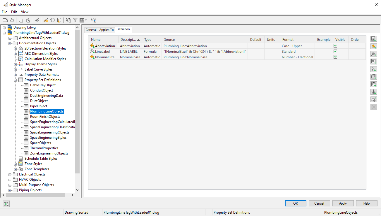
It occurred to me that, for the stated case of a short Plumbing Line, that the masking and repeating features were not necessary, and that a Schedule Tag, which can have an integral leader, could be created that looks just like the Label Curve, if the data displayed by the Label Curve was available in Property Data. It turns out that, at least for the Standard - Pipe With System Label Label Style, which shows the Object Props. and Abbr. System Name, Plumbing Lines have corresponding Automatic Property sources: Nominal Size and Abbreviation. I was able to create a Property Set Definition that applies to Plumbing Lines and includes three properties:
  • Abbreviation, created from the Abbreviation automatic property source. The Case - Upper Property Data Format was applied to this property.
  • NominalSize, created from the Nominal Size automatic property source. Since I was working in imperial units (it is one of my habits), I applied the Number - Fractional Property Data Format to this property.
  • LineLabel, a formula property, creates the string that is to be displayed in the Schedule Tag. It is a simple concatenation of the text equivalent of the NominalSize property, an inches symbol [via Chr(034)], a space and the Abbreviation property. The Standard Property Data Format was applied to this property.
A Schedule Tag can then be created to display the value in the LineLabel property, a Schedule Tag tool can be created for that Schedule Tag, the tool properties can be edited to include a leader and then the tool can be used to place a tag with a leader. The result can be seen in the image below, where the short Plumbing Line segment has both an offset Label Curve and a Schedule Tag with a leader, so you can compare the two.

November 15, 2019

ACA-AMEP: Edit Property Data Via AutoLISP, Part 3

First article in the series.
Previous article in the series.

In the previous article, we used a while loop to examine each Property Set in the collection of Property Sets attached to the object of interest, comparing each Property Set's Name to the name of the Property Set that holds the Property whose value is to be changed. At this point, there are two possible conditions:
  1. A matching Property Set was found. The value in the Property Set counter variable, iPSet, was set to one more than the number of Property Sets in the collection (variable iPSets).
  2. A matching Property Set was not found. The value in the Property Set counter variable, iPSet, will be equal to the number of Property Sets in the collection (variable iPSets).
(cond    ; Cond A.
  ((= iPSet iPSets)
   ;; If the Property Set is not found after processing all attached property sets, issue prompt.
   (prompt
     (strcat
       "\nProperty Set "
       sPSet
       " not found on object passed to argument obj. "
     ) ;_ End strcat.
   ) ;_ End prompt.
   nil    ; Return nil.
  ) ;_ End condition A1.
  (T    ; Else, continue.
   (setq oProps (vlax-get-property oPSet 'Properties)
          ; Get Properties object of the Property Set.
         iProps (vlax-get-property oProps 'Count)
    ; Get number of Properties in the Property Set.
         iProp  0  ; Initialize Property counter.
   ) ;_ End setq.

   (while (< iProp iProps) ; While unprocessed Properties remain...
     (setq oProp   (vlax-invoke-method oProps 'Item iProp)
    ; Get current Property object.
    sPropNm (vlax-get-property oProp 'Name)
    ; Get Property name.
     ) ;_ End setq.
     (if (= (strcase sPropNm) (strcase sProp))
        ; If target Property found...
       (setq iProp (1+ iProps)) ; ...exit while loop.
       (setq iProp (1+ iProp)) ; ...else, increment Property counter.
     ) ;_ End if.
   ) ;_ End while.

   (cond   ; Cond A2B.
     ((= iProp iProps)
      ;; If the Property is not found after processing all Properties in the Property Set, issue prompt.
      (prompt
        (strcat
          "\nProperty "
          sProp
          " not found in Property Set "
          sPSet
          " attached to the object passed to argument obj. "
        ) ;_ End strcat.
      ) ;_ End prompt.
      nil   ; Return nil.
     ) ;_ End condition A2B1.
     (T    ; Else, update Property value with processed value.
      (setq varPropValOld (vlax-get-property oProp 'Value))

      ***** ADD CODE HERE TO GENERATE THE DESIRED NEW VALUE   *****
      ***** SET VARIABLE sPropValNew to the NEW DESIRED VALUE *****

      (vlax-put-property oProp 'Value sPropValNew)
      sPropValNew   ; Return new string value.
     ) ;_ End condition A2B2.
   ) ;_ End cond A2B.

  ) ;_ End condition A2.
) ;_ End cond A.

Here is what is happening in that code:
  • A cond statement is used to determine which of the two conditions noted above is active. The first test checks to see if iPSet and iPSets are equal. If this is true, then the target Property Set was not found, and there is nothing to process. A prompt is written to the command line to inform the user. I have a separate subroutine to hold this code, so after issuing the prompt, this condition returns nil to the calling routine, to indicate that the requested Property Set was not found. The calling routine can then choose how to handle that situation.
  • If iPSet and iPSets are not equal, then the target Property Set was found and we can continue on. The test for this condition is T (True), because if the first test is false, no further test is required, and the code to process will be contained within this condition.
  • Variable oPSet holds the Property Set object whose name matched the target Property Set name. The Properties property of the Property Set object is used to obtain the Properties collection of that Property Set. The Properties collection contains all of the individual Property objects that are defined in that Property Set Definition.
  • The Count property of the Properties collection is used to determine the total number of Properties in the collection (variable iProps). A variable to hold the Property counter, iProp is initialized to 0, the index of the first Property in the collection.
  • Similar to the way we iterated over the Property Set collection, a while loop is used to iterate over the Properties collection, looking for a Property whose name matches the target property name, which is held in variable sProp. If a match is found, iProp is set to one more than the total number of Properties in the collection. If a match is not found, then iProp is incremented by 1, so that the next Property in the collection will be processed on the next pass of the loop, if at least one unprocessed Proeprty remains.
  • At this point, there are two possible conditions:
    1. A matching Property was found, and the value of iProp is one more than the value of iProps
    2. A matching Property was not found, and the values of iProp and iProps are equal.
  • Once again, a cond statement is used to run the appropriate code. If a matching Property was not found, the first condition writes a prompt to the command line to inform the user that the Property was not found, and returns nil to the calling routine, to indicate that the requested Property was not found in the requested Property Set. The calling routine can then choose how to handle that situation.
  • If the target Property was found, then the first condition will not be executed, and the second condition will be executed, as the test is set to T.
  • The Value property of the Property object is used to obtain the current value, storing it in variable varPropValOld.
  • At this point, you will need to add the code that generates the new value for the target Property, saving that value to variable varPropValNew
  • The vlax-put-property function is used to push the new value onto the Value property of the Property Object. This condition then returns the new value to the calling routine.
  • All of the currently open conditions and cond functions are then ended.

If you choose to have all your code in a single AutoLISP command function, then instead of returning nil or varPropValNew at the end of the A1, A2B1 and A2B2 conditions, you would add whatever additional code you may feel appropriate to run prior to the end of your command function.

November 05, 2019

ACA-AMEP: Edit Property Data Via AutoLISP, Part 2

First article in the series.

In the previous article, we obtained a collection of the Property Sets on the object for which we want to change the value of a Property. We also determined the total number of Property Sets in the collection, and set up a Property Set counter, initialized to 0, the index of the first Property Set. The following code assumes that you know not only the name of the Property that is to be changed, but also the name of the Property Set in which it resides and that the name is stored in a variable called sPSet.
(while (< iPSet iPSets)  ; While unprocessed Property Sets remain...
  (setq oPSet   (vlax-invoke-method oPSets 'Item iPSet) ; Get current Property Set object.
        sPSetNm (vlax-get-property oPSet 'Name)         ; Get Property Set name.
  ) ;_ End setq.
  (if (= (strcase sPSetNm) (strcase sPSet))             ; If target Property Set is found...
    (setq iPSet (1+ iPSets))                            ; ...exit while loop.
    (setq iPSet (1+ iPSet))                             ; ...else, increment Property Set counter.
  ) ;_ End if.
) ;_ End while.

Here is what is happening in that code:
  • A while loop is used to iterate over the Property Sets collection. The Item method is used to get the Property Set at the current index value in iPSet.
  • The Name property of the Property Set object is used to obtain the name of that Property Set.
  • An if statement is used to determine if that Property Set name matches the target Property Set name. The strcase function is used to change both strings to all capital letters, to avoid any issues with different capitalization of the names. If a match is found, the iPSet index counter is set to a number one greater than the total numnber of Property Sets in the collection, so that the loop will be exited. If a match is not found, the iPSet index counter is incremented by 1, so that the next Property Set in the collection will be processed on the next pass of the loop, if at least one unprocessed Property Set remains.

Next article in the series.

November 01, 2019

ACA-AMEP: Edit Property Data Via AutoLISP, Part 1

Sometimes you need to make changes to the values of a Property on all or many AEC Objects in a file. If that change can be done programatically (example, in a text-type manual Property, edit the text value, replacing all occurrences of "1ST" with "2ND"), and there are a large number of Objects to process, it may be easier to do so via AutoLISP, than to manually edit each value. This series of articles will show you how to do so.

NOTE: I have only used this technique on manual Properties. I am not certain what would happen if you tried to use this to change the value of an automatic property. I suspect the change may fail, at least in some cases, like formula Properies. Even if it works for some automatic Properties, such as the height or width of a Door, doing so may have unexpected results in the drawing. If you have a use case for trying to edit the values of automatic Properties, please test this thoroughly on copies of files, or files created strictly for testing purposes, not on actual project files, until you are certain there is no harm.

The VisualLISP commands will be used to access the object model. You will also need to operate on vla-objects. If your method of getting the selection set on which to operate results in AutoLISP entity names, these can be converted to vla-objects by using the
(setq obj (vlax-ename->vla-object ename))
function, where obj is the name of a variable holding the vla-object and ename is the name of a variable holding the entity name of the object on which you want to operate.

Getting to the Property value is not a matter of simply querying the object for it. You will need to drill down into the object model. Start with the following code. You can use different variable names if the ones used in the example code here do not conform to your naming standard. Just make certain you substitute your names consistently.
(vl-load-com)
(setq objAcad    (vlax-get-acad-object)  ; AutoCAD Application Object.
      objAecSchd (vla-GetInterfaceObject objAcad (strcat "AecX.AecScheduleApplication" (aecappver)))
                                         ; AecScheduleApplication object.
      oPSets     (vlax-invoke-method objAecSchd 'PropertySets obj)
                                         ; Get PropertySets collection object.
      iPSets     (vlax-get-property oPSets 'Count)
                                         ; Get number of Property Sets in the PropertySets collection object.
      iPSet  0                           ; Initialize Property Set counter.
) ;_ End setq.

Here is what is happening in that code:
  • The (vl-load-com) function loads the VisualLISP functions, if they are not already loaded. If they are loaded, it does nothing.
  • The first item in the setq function gets the AutoCAD object. This is then used to get the AEC Schedule Application object. This object is version-specific, so I use a subroutine I put together to return the version string, called AECAPPVER. You can find the code for that routine in this previous article. The article was updated to support versions through 2020.
  • The third item in the setq function uses the PropertySets method of the AEC Schedule Application object to get the PropertySets collection for the object on which we want to operate (which is held in the obj variable).
  • The final two items in the setq function determine the number of Property Sets that are in that collection, and initializes a Property Set counter to 0, which is the index of the first Property Set in the collection.

Next article in the series.

April 11, 2017

ACA: Property Set Definitions, Applies To - Just How Many Polyline Types Are There?

If you ever want to do any scheduling in AutoCAD® Architecture that involves polylines, you will find that there are three different polyline types to which your Property Set Definition can apply. You could select all three, to be safe. Here is an explanation of what each type is, should you want to be more precise (or want to explicitly exclude any of the types).

  1. Polyline: This choice applies to "modern," so-called "light-weight" LWPOLYLINEs. If you have PLINETYPE set to 1 or the default value of 2, then the PLINE command will make this type. (If it is set to 2, and you open an R14-format drawing (or older), any existing polylines will be converted to the the "new" format; if it is set to 1, existing polylines from R14 or older format drawings are not converted.)
  2. Polyline (2D): This choice applies to the old format polylines. You have to set PLINETYPE to 0 to create new polylines in that format. Unless you have a compelling reason to do so, I would not recommend that. The LWPOLYLINE format results in smaller file sizes and faster processing.
  3. Polyline (3D): This choice applies to 3D polylines created with the 3DPOLY command. Polylines created by the PLINE command are "flat" or 2D; all vertices have the same Z-coordinate in the UCS that was current at the time of creation, set by the first point selected. In a 3D polyline, the Z-coordinate of each vertex is independent of those of the other vertices.
If you select a polyline to which the Polyline choice applies, the Properties palette will show it as "Polyline" at the top. If you use the LIST command, it will indicate that it is a "LWPOLYLINE".

If you select a polyline to which the Polyline (2D) choice applies, the Properties palette will show it as "2D Polyline" at the top. If you use the LIST command, it will indicate that it is a "POLYLINE".

If you select a polyline to which the Polyline (3D) choice applies, the Properties palette will show it as "3D Polyline" at the top. If you use the LIST command, it will indicate that it is a "POLYLINE".

Here are the Automatic Properties that are available with each type. Note that the Polyline and Polyline (2D) have the same Automatic Properties; Polyline (3D) has some of the same, but lacks the Closed, Elevation and Thickness properties.

June 29, 2015

ACA: Classification Definitions, Applies To and Tagging

Classification Definitions have been around since Autodesk® Architectural Desktop 2004. One use for them is to act as an additional filter for the AEC objects that can be included in a Schedule Table; unlike layer filters, Classification Definition filters can be built right into the Schedule Table Style, on the Applies To tab. You can also use them on Property Set Definitions to limit the objects to which you can attach a Property Set.

I have been using them to control what objects are seen in Schedule Tables for quite some time now. A recent thread in the AutoCAD® Architecture General Discussion Group had me wondering if they could be used to prevent a Schedule Tag from being placed on an item, theorizing that if a Classification Definition was set up such that the Property Sets referenced by the Schedule Tag did not apply to a particular object, perhaps I would be unable to tag that object.

To test my hypothesis, in the 2016 release, I created a Classification Definition called Schedule that applies to all objects, with two Classifications: Schedule and No Schedule.

I then applied this Classification Definition to the Property Set Definitions referenced by the out-of-the-box US Imperial Door Tag (non-project), classifying each as Schedule.

Finally, I applied the Classification Definition to the Door Styles, on the Classifications tab of each style. In my test file, the Hinged - Single, Hinged - Double and Sliding - Double - Full Lite Door Styles were set to Schedule, and the Cased Opening Door Style was set to No Schedule.

I placed a few instances of the Doors (two of the Cased Opening style, one each of the others). On the Extended Data tab of the Properties palette, I observed that the Add Property Sets button was grayed out for the Cased Opening Doors, as it should be, since the DoorObjects Property Set does not apply due to the classification being set to No Schedule for those Doors. I edited the Cased Opening Door Style, and, on the General Tab, selected the Property Sets button and manually removed the FrameStyles, DoorStyles and ManufacturerStyles Property Sets (which were attached in the source file). Once I did so, the Add Property Sets remained grayed out, due to the classification.

At this point, I used the out-of-the-box US Imperial Door Tag tool (Document tool palette group, Tags palette) and attempted to tag each of the doors. As you can see in the image below, I was not prevented from tagging the Cased Opening Doors, even though none of the referenced Property Sets could be applied to those Doors. I did get a Command line message stating: Note: Not all properties apply to selected object. The DoorObjects Property Set was not applied to these Doors, and the Schedule Tag displayed the default value assigned to the attribute definition in the tag's view block. Surprisingly, the style-based Property Sets were attached to the Cased Opening Door Style, even though those did not apply, either.
In the image above, I turned on the display of the Anchor Extended Tag to Entity component, and set its color to green. The green arcs extending from the Schedule Tag insertion point to the Door origin point are these anchor components, verifying that the Tags on the Cased Opening Doors are in fact anchored. I also repeated this experiment, with a custom Schedule Tag that only referenced one object-based Property Set, but the Cased Opening Doors still received the tag, even though the referenced Property Set was not attached. Similar results were obtained in the 2015 release as well.

So, using a Classification filter to limit the objects to which Property Set Definitions apply will not prevent a Schedule Tag that references properties in such a Property Set Definition from being anchored, and will even add any style-based Property Sets referenced by the Schedule Tag. Object-based Property Sets will not be attached, and attributes that are set up to display the value of object-based properties will only show the default attribute value.

May 26, 2015

ACA/AMEP 2016: Property Visibility Override

Prior to the 2007 release of what was then called Autodesk® Architectural Desktop, all properties in a Property Set Definition attached to a selected item were displayed on the Extended Data tab of the Properties Palette, and they were displayed in alphabetical order. In response to user requests, the 2007 release added two columns to the Definition tab for Property Set Definitions, one titled Visible with a toggle that allowed you to choose whether or not each property would be displayed on the Extended Data tab, and one titled Order that allowed you to specify the the order in which the properties were shown.
In the image above, the Visible and Order columns can be seen at the far right; the properties in the Style Manager are sorted by the Order column because I clicked on that column header before making the screen capture. The ObjectID automatic property will not be seen on the Extended Data tab of the Properties palette because the toggle in the Visible column has been cleared.

These additions allowed those setting up the standards for an office to make interacting with property data easier for the end users by ordering the properties logically and hiding any properties whose values the end user cannot change and which the end user has no workflow reason to reference. But it does pose one small problem for the person managing the office's standards - it can be hard to trouble shoot an issue if you cannot see all of the values of the properties that go into the ones that do show up on a Schedule Table or that are shown on the Properties palette.

Until now, the manager would need to temporarily turn on the display of those properties, or set up a working Schedule Table that displays all of the properties, both of which can be cumbersome. In the 2016 release, the manager can use the newly added AECPSDVISIBILITY system variable to override just the visibility settings (AECPSDVISIBILITY = 1) or both the visibility and the order settings (AECPSDVISIBILITY = 2). Setting AECPSDVISIBILITY to the initial default value of 0 will remove the overrides and return property display back to normal.

The value of the AECPSDVISIBILITY system variable can be set at the Command: line or in the Options dialog, on the AEC Objects Settings tab, in the AEC Property Set Definitions area at the lower left, by using the Property Override drop down.
None is "0", Visibility is "1" and Visibility and Order is "2".

The AECPSDVISIBILITY setting applies to all drawings open within a given drawing session, as well as any drawings opened later in that same session, until/unless manually changed. It is not, however stored in any of the drawings, and when you close the program and then reopen it, the value will be back at the initial default value of 0. One other item to note: when AECPSDVISIBILITY is set to 1 or 2, the Visible column on the Definition tab will be grayed out and unavailable for editing.
Setting the value of AECPSDVISIBILITY back to 0 will allow you to edit the Visible column settings again.

December 12, 2013

ACA: Formula Property to Determine if a Block Instance is a Dynamic Block

You can use the following code in an AutoCAD® Architecture Formula Property in a Property Set that applies to Block References to determine if the Block Reference is a Dynamic Block.
set acadApp = GetObject(,"AutoCAD.Application")
set obj = acadApp.ActiveDocument.ObjectIDToObject( [ObjectID] )
RESULT = obj.IsDynamicBlock

As in the previous example, [ObjectID] is a properly created property reference to an automatic property in the same Property Set, named ObjectID, which references the Object ID automatic property source. This formula will return a value of TRUE if the block reference is a Dynamic Block and FALSE if the block is a "regular" block. The property can be used as the condition for an IF Statement, if you need another Formula property to take different actions based on whether or not the block reference is a dynamic block.

December 10, 2013

ACA: Obtaining the Effective Name of a Dynamic Block in a Formula Property

While Dynamic Blocks and ACA do not always play nicely, there are some who want to take advantage of both Dynamic Blocks and the AutoCAD® Architecture Schedule feature. One challenge is that the Name automatic property source may return an anonymous block name rather than the Dynamic Block name; for example, when a Dynamic Block with a stretch action is stretched. Fortunately, you can obtain the orignal block name from the EffectiveName property of the Dynamic Block instance, in a Formula property, using the the following VBScript code:
set acadApp = GetObject(,"AutoCAD.Application")
set obj = acadApp.ActiveDocument.ObjectIDToObject( [ObjectID] )
RESULT = obj.EffectiveName

The Property Set Definition that includes the Formula property will also need to have a property that references the Object ID automatic property source. In the example code above, this property has the default ObjectID name, and the [ObjectID] text in the formula represents a properly created property reference, created by double-clicking the property name in the Insert Property Definitions box in the lower left of the Formula Property Definition dialog.

March 26, 2013

ACA 2014: Property Set Defintion Auto-attach

AutoCAD® Architecture 2014 has a new feature that allows you to enable the automatic attachment of Property Set Definitions [PSDs] to objects. This setting is on a by-drawing basis, so you can have this turned on in some drawings and off in others.

To turn on this feature, open the Options dialog and go to the AEC Object Settings tab. In the lower left corner, in the AEC Property Set Definitions area, clik the Automatically Attach toggle so that it has a checkmark. (Note also the drawing icon next to this item, indicating that this setting is saved in the drawing, and not in your Windows registry, so any change affects only this drawing.)

You can also use the AECPSDAUTOATTACH command at the Command Line to control this setting. ON or 1 enables the auto-attach feature; OFF or 0 disables it.


When Auto-attach is enabled, any existing PSDs in that file will be automatically attached to all objects or styles/definitions to which a specific PSD applies and to which the PSD had not been previously attached. When a new object is created, any applicable object-based PSD will be automatically attached; when a new style or definition is created or imported, any applicable style-based PSD will be attached.

Here are some observations and comments based on working with this feature:
  1. While working outside of the ACA Drawing Management environment (Project Browser and Project Navigator), if you have a file ["File A"] with objects/styles that do not have certain PSDs that apply to those objects/styles attached, and you externally reference File A into a second file ["File B"] which has those PSDs in it and which also has Auto-attach enabled, the style-based PSDs in File B will be attached to the applicable styles/definitions in File A and the save time and date for File A will be updated. If style-based PSDs of the same name exist in File A (but were not previously attached to one or more styles/definitions), then the version in File A will be attached, even if it differs from the version in File B. If a style-based PSD of the same name does not exist in File A, then the style-based PSD will be copied from File B to File A. If there are no style-based PSDs in File B, or if there are style-based PSDs in File A with the same names and those are already attached to the styles/definitions in File A, then no action will be taken on File A.
  2. In the same scenario as Item 1 above, if there are style-based PSDs to be attached to objects in File A and if File A is from a previous file format, you will get a warning dialog and be given the choice to either proceed, saving File A in the current file format (2013, for ACA 2014) or to not save File A, discarding the "changes from this session" - in other words, not attaching the style-based PSDs in File A.
  3. In the same scenario as Item 1 above, the object-based PSDs in File B will be attached to the objects in File A, but only as property data overrides in File B. If those PSDs are later attached in File A, any values added there that are different from those in File B will not show in File B due to the property data override.
  4. In the same scenario as Item 1 above, if File A is open at the time it is being externally referenced into File B, the file lock on File B will prevent any style-based PSDs from being added to File A when Auto-attach is enabled. Once this fails, neither subsequent saving, closing or re-opening of File B nor moving the external reference instance within File B will trigger adding the style-based PSDs to File A. XATTACHing another instance of File A within File B will trigger another attempt to push the style-based PSDs to the File A.
  5. In the ACA Drawing Management environment (Project Browser and Project Navigator), the Auto-attach feature works the same way as noted above when working outside of it. I had expected that object-based PSDs being auto-attached to an object in an externally referenced Construct in a View file would have been attached at the Construct level, either directly on an object in the Construct, or as a property data override in the Construct to an object in a nested external reference (Element) within the Construct. That is how PSDs are treated when tagging an item through an externally referenced Construct in a View file.
Overall, I think I will be recommending that this feature remains turned off in most situations. Where it makes sense to activate it, it should be turned back off once its work has been done. It might work to turn it on in the "base" or model files (equivalent to Constructs) but it should be off in "sheet" files (or, in the Drawing Management environment, in Views and Sheets ), so that unwanted property data overrides are not introduced. I would rather have the project teams have to manually attach missing property sets in the proper place, the model file, than to have it appear to be attached in one sheet file, but have the data only exist in that one sheet file, as an override, than on the actual object, which could be externally referenced by other files.

June 26, 2012

ACA: Occupancy Load Calculations with a Column Total

In the thread in the Autodesk AutoCAD® Architecture Discussion Group that was the basis for my previous blog article post on occupant load calculations, Ted Evans pointed out that if you add a total to the occupant load column, the sum may not reflect the total of the displayed values. He is correct, if the displayed values have a sufficient number of cases where small fractional amounts were rounded up. Because any fractional amount is being rounded up in this case, there is no opportunity for round ups to be offset by round downs, making the fact that ACA uses the unformatted values when calculating the total even more apparent than in a situation where rounding is done to "nearest".

My reply today explained the reason why the total was not the same as the sum of the displayed numbers, and I indicated that in order for the total to be correct, the rounding should be done within the formula property, rather than by the Property Data Format. [For other options, see this blog article, which includes several means of achieving real number rounding and getting correct column totals.]

By placing the results of each branch of the second If statement in a variable [occs] instead of making it the RETURN value, I was able to then process the value in variable occs. If occs is not a whole number (that is, if subtracting the integer portion of occs from itself does not result in a value of zero), the value of occs is reset to the integer portion of occs plus one. Otherwise, occs is a whole number, and rounding up is not necessary. The revised formula is shown below; a sample file was included in my reply in the Discussion Group.
occLoad = [SpaceStylesCalcs:Occupant_Load]

If occLoad = 0 Then
 doCalc = 0
 occLoad = 1
Else
 doCalc = 1
End If

If doCalc = 1 Then
 occs = [SpaceStyles:BaseArea] / occLoad
Else
 occs = 0
End If

If occs - Int (occs) <> 0 Then
 occs = Int (occs) + 1
End If

RESULT = occs

June 24, 2012

ACA: Occupancy Load Calculations and Division by Zero

A question concerning occupancy load calculations and how to handle Spaces to which an occupant load of "0" has been assigned was posted to a thread in the Autodesk AutoCAD® Architecture Discussion Group. Dividing the Space's area by the occupant load causes an error in the formula when the occupant load is zero. As noted in my response, which includes a sample file done in ACA 2011, a simple If statement cannot be used test for a zero value and then avoid the calculation, because VBScript will evaluate the entire statement, including logical paths that would not be taken, and still end up in an error condition.

My solution was to use a variable (called occLoad in the example) to hold the occupant load property value and two If statements. The first tests for a zero value and sets a variable (called doCalc in the example) to indicate whether or not a calculation should be done. If it finds a zero value, the doCalc variable is set to 0 (do not calculate) AND the occLoad value is changed from 0 to 1. If occLoad is not zero, the first If statement only sets doCalc to 1 (do calculate).

The second If statement then tests the value of doCalc: if it is 1, it returns the result of dividing the area by the occupant load; if it is 0, it returns 0. Because the first If statement assures that the occLoad value will not be zero, the division in the second If statement never results in an error condition, and the desired result for an occupant load of zero is returned.
occLoad = [SpaceStylesCalcs:Occupant_Load]

If occLoad = 0 Then
 doCalc = 0
 occLoad = 1
Else
 doCalc = 1
End If

If doCalc = 1 Then
 RESULT = [SpaceStyles:BaseArea] / occLoad
Else
 RESULT = 0
End If

The example file also shows how a Property Data Format can be used to round any result with a fractional amount up to the next highest integer, since you would want that when calculating occupant loads for egress analysis. It also demonstrates using a style-based Property Set to hold the occupant load property, so that the occupant load value only needs to be added to the Space Style, and not to each individual Space.

February 12, 2012

ACA: Extracting Text from a Style Name

In a recent reply post in the Getting steel beam size thread in the Autodesk AutoCAD® Architecture Discussion Group, Dallas asked if there was a way to automatically extract a value embedded in the name of a Structural Member Style. The specific example was if the style name were to include the shape size followed by the depth in parentheses: W16x45 (16.13).

I replied with a file attachment that had a sample file demonstrating that this was possible. The style-based StrMembStyles01 Property Set Definition, which applies to Structural Member Styles, in that file contains an Automatic property called Style that uses the Style automatic property source to make the style name available. The MemberDepth property uses the following VBScript code to extract the value between the parentheses in the style name and convert it to a real number:
styleName = "[Style]"
startChar = InStr( "[Style]",  "(" ) +1
endChar = InStr(  "[Style]",  ")" )
strLen = endChar - startChar

If strLen <= 0 Then
 memberDepth = 0
Else
 memberDepth =  Mid( styleName, startChar, strLen )
End If

If Not IsNumeric( memberDepth ) Then
 memberDepth = 0
End If

RESULT = CDbl(memberDepth)
Notes:
  1. The first line assigns the text string in the [Style] property to the variable styleName. As always, you cannot simply type or paste a property reference in a formula property. You have to insert them by placing your cursor in the upper left edit box and then double click the property in the list in the lower left box.
  2. The second line uses the VBScript InStr function to determine the position of the first character of the depth value embedded in the style name, which is presumed to be the first character after the first open parenthesis character, "(", found in the string. This is saved in the variable startChar.
  3. The third line also uses the InStr function to save the position of the first close parenthesis character, ")", to the variable endChar. In both the second and third lines, I probably should have used the styleName variable in lieu of additional references to the [Style] property.
  4. The fourth line assigns difference between startChar and endChar to the variable strLen, which is the length of the string that gives the member depth. Using the InStr function with delimiter characters avoids the need to have a fixed number of characters before the depth value and a fixed number of characters for the depth. The only requirement is that the first "(" character in the name immediately precede the depth value, and the first ")" character immediately follow the depth value.
  5. At this point, we have all of the information we need to get the string representing the member depth. If the Property Set gets attached to a Structural Member Style whose name is not properly formatted (no parentheses, first "(" is either preceded by or immediately followed by the first ")", one or more non-numeric characters between the first "(" and ")") and the resultant string is converted to a double precision number, an error will result. The formula property is set up to return a depth of 0 for improperly formatted style names. All of the mentioned error conditions except for non-numeric characters will result in a string length of 0 or less. The first If statement checks for this condition and sets variable memberDepth to 0 if true; otherwise it extracts the string between the first "(" and first ")".
  6. The second If statement tests the extracted string to verify it either is numeric or is a string that can be evaluated as numeric using the IsNumeric function, preceded by the Not operator. If the extracted string is not numeric, the value of memberDepth is reset to 0, otherwise, it is left as is.
  7. At this point, the value of memberDepth is either 0 or a numeric string, and can be converted to a double precision real number using the CDbl function. It is up to whatever additional use you make of this property to determine how to handle a value of 0.
Download the sample file attached to my post to see this formula property in action.

November 25, 2011

Rounding and Column Totals

If you have a Schedule Table column that displays real-number values that are rounded by the applied Property Data Format and you also display a total for the column, you may find that the total displayed does not equal the sum of the individual numbers displayed. This can happen because ACA uses the real-number values before the format is applied when calculating the total, and then applies the Property Data Format to the result. So if there is not a balance between round up amounts and round down amounts, the total can differ from the sum of the displayed, rounded numbers.

If this bothers you (it bothers me), you can make use of the same techniques discussed in this blog article, where the task was to get rows with apparently similar values to collapse into one row in a Schedule Table with a Quantity column. The rows were not collapsing because even though the displayed, rounded numbers were the same, ACA was using the actual values, before applying the Property Data Format, to determine whether or not the values were the same.

In response to an inquiry in the Autodesk ACA Discussion Group, I posted a sample file (AutoCAD 2010 format) demonstrating several ways a Formula property can be used to make the source value the same as the rounded value, so that the total for the column will be the sum of the displayed values (and, if you have a Quantity column, that rows with identical displayed values will collapse). The image below shows the test Schedule Table I set up to show how the various properties in the SpaceObjectAreas Property Set display. The file was created using the Aec Model (Metric Stb).dwt template and the AutoCAD Architecture (US Metric) profile.

The columns in that Schedule Table display two properties from the out-of-the-box SpaceObjects Property Set Definition: Name and Number. The remaining columns display properties from a custom Property Set Definition called SpaceObjectAreas. Here is a description of these properties, and the effect that the way they are set up and formatted has on the values displayed and the column total.
  • BaseAreaUnformatted: This property, displayed in the column titled "UNFORMATTED", uses the Automatic Base Area property of Spaces to display the area of the space. A custom Property Data Format called Standard-8 has been applied to this property and to the column in the Schedule Table. This is a copy of the out-of-the-box Standard Property Data Format, with the real-number precision changed to eight decimal places and trailing zero supression turned off. There is also no prefix or suffix applied to the value, so when referenced by formula properties, the value will be treated as a numeric value. The areas of the test spaces do not generate any rounding issues when totalled, as they do not require more than the eight digits displayed.
  • BaseArea: This property, displayed in the column titled "AREA FORMAT", also uses the Automatic Base Area property of Spaces. It has the out-of-the-box Area Property Data Format applied to it, which in its metric version displays real numbers using an Area unit type, units of square meters, decimal unit format with two-decimal-place precision and a suffix of " M2". Other than Space 101, the area of each space is rounded up when displaying the value to two decimal places. The total is rounded based on the total of the raw values (see the Unformatted column total), and results in a column total that is 0.04 M2 less than the total of the displayed numbers.
  • BaseAreaPassThrough: This property, displayed in the column titled "PASS THROUGH", is a Formula property. It takes the BaseArea property and uses the feature added in ACA 2007 that allows you to assign a different Property Data Format for the purposes of the Formula property. In the example file, a custom Property Data Format called Standard-2 is assigned, which is a copy of the out-of-the-box Standard Property Data Format, with the real-number precision changed to two decimal places and trailing zero suppression turned off. The Formula takes the value of BaseArea (rounded to two decimal places by the Standard-2 Property Data Format), makes it a string, converts that to a double-precision real number and passes it through as the final value. Since we want to have a total value for the column, using the default Area Property Data Format would not work, since this includes a suffix of " M2", which would cause the value to be interpreted as a string and therefore not provide a numeric value that can be totaled. Because the Property Data Format has trailing zero suppression turned off, the CDbl conversion is not required, but because I know this value should always be a number, I put it in, should the Property Set ever get copied to a file that already has a Property Data Format called Standard-2 that has trailing zero supression turned on. In that case, if the BaseArea value was a whole number, the result would be interpreted as an integer in ACA and the real-number formatting would not be applied.
    Because the Formula property is generating the "raw" values with the area values rounded to two decimal places, the column total reflects the total of the actual values displayed, rather than the rounded sum of the source areas of the actual Spaces.
  • BaseAreaRounded_01: This Formula propery is displayed in the column titled "FORMULA ROUNDING 0.01". It accomplishes the exact same effect as the pass-through Formula, but uses the VBScript Round function to do so. CDbl( Round( [BaseArea], 2 ) ) It also assigns a different Property Data Format to the BaseArea property (Standard-8, in this case). In the example file, I could have simply referenced the BaseAreaUnformatted property without reassigning the Property Data Format in the Formula property, but I used the BaseArea property with the reassigned Property Data Format to demonstrate that you do not need to set up a separate, unformatted version of an automatic property if you are using the 2007 or later version. I included the unformatted property here so that I could display the area values to eight decimal places in the Schedule Table, so you could see the effects that the various formatting/rounding options had on the raw numbers. As with the previous formula, the column total matches the sum of the displayed values, because the raw value of the Formula property is the same as the displayed value. If you can achieve the precision and rounding you want with a Property Data Format, then you can use either the pass-through or the Round function method. As you will see in the final example, the Round function (combined with other mathematical operations) can do things that the Property Data Format cannot do, in which case the Round function would be the only choice.
  • BaseAreaRounded_05: As seen in the column titled "FORMULA ROUNDING 0.05", this Formula property rounds the area value to the nearest 0.05, and since the raw values are the actual rounded values, the column total is correct for the displayed values. CDbl( Round( ( [BaseArea] / 0.05 ), 0 ) * 0.05 ) The formula achieves the desired rounding by starting with the BaseArea property value, with the Standard-8 Property Data Format applied. It divides that value by 0.05, rounds the result to the nearest whole number and finally multiplies that result by 0.05 to achieve the desired result. I am not certain how often something like that might be used in a metric file (you could use the same technique to round to the nearest half-square meter, just change the "0.05" to "0.5"), but there are occasions, when using imperial units, that rounding room areas to the nearest 25 or 50 square feet is used as a means of not implying too much precision in early test fits.
In all of the Formula properties, the Area Property Data Format is applied to the property (and the column in the Schedule Table) to get the " M2" suffix applied to the value calcuated by the formula. Also remember that when specifying a property reference in a Formula property, you have to select the referenced property from the Insert Property Definitions box in the lower left corner of the Formula Property Definition dialog; you can not simply type in the name of the property, enclosed in square brackets. If you are interested in reading more about rounding in Formula properties or some of the other techniques discussed above, you may want to check out some of these earlier blog articles:
07/09/2005 - Unformatted Properties and Numeric Precision
08/31/2005 - Rounding Up Property Data Values
08/31/2005 - Rounding Revisited
09/03/2005 - Rounding Redux
09/15/2005 - Rounding to Death
05/01/2006 - Using Property Data Formats to Force Real Number Interpretation
04/15/2007 - ACA 2008/ADT 2007: Setting a Different Property Data Format in a Formula Property
06/16/2007 - Rounded Values and the Quantity Column

July 23, 2011

ACA: Adding a Style-Based Property Set

A style-based Property Sets is handy in that you only need to attach it to the Style or Definition once, and then it travels with the Style without any additional effort on your part. Most automatic properties are good candidates for a style-based Property Set, as are manual properties whose values remain constant for all instances of the Style or Definition. Location properties should generally be in object-based Property Sets, since the location grip will not be generated unless the object has at least one Location property in an object-based Property Set.

Creating a style-based Property Set is quite easy. When creating the Property Set Definition in the Style Manager, indicate that it should apply to Styles and Definitions by using the radio button at the top of the Applies To tab.
Then pick the object type(s) to whose style(s)/definition(s) the Property Set Defintion is to apply. Go to the Definition tab and add the properties you want in the set, if you have not already done so.

Now that you have a style-based Property Set Definition, you need to attach it to one or more styles/definitions (of the type you chose on the Applies To tab). In the Style Manager, create/edit such a style or definition. On the General Tabclick on the Property Sets... button. This will open the Edit Property Set Data dialog. If your style or definition does not already have a style-based Property Set attached, the dialog will be blank. Click on the Add Property Sets button (right button at the lower left corner). Note that the button will not be active if there are no style-based Property Sets in the current drawing that apply to the object style/definition being edited and that have not already been added. In the Add Property Sets dialog, review the list of eligible Property Sets and make certain that a check mark is in front of all those you wish to add (and not in front of any you do not want to add), and then click OK to add the Property Sets.This will return you to the Edit Property Set Data dialog, and you can review the attached properties and, if there are manual properties, you can set the desired values. Also note that now that this style has a Property Set added, the Remove Property Sets button is now active (right button at lower left, next to Add Property Sets button). Click OK to accept the changes you made, and now your style-based Property Set is attached and the Properties therein are available to Schedule Tables and Schedule Tags.
For office-standard style-based Property Sets, you will want to add the set to your style/definition source file, so when users add the style/definition to a drawing, the Property Set is already attached.

April 09, 2011

Location Property Misread

If you are experiencing Location properties not reading the correct property when working through external references, you may want to see if the problem is similar to one I recently experienced.

A project in my office was being done in ACA 2010, and was not using the Drawing Management (Project Browser/Project Navigator) feature. Space objects were placed in the main "model" file, and had the company standard Property Set attached which includes two Text-type Manual properties for the room name (for two separate lines, set up before attributes in the view block of a Multi-View Block tag could wrap text), a formula property to concatenate those two Manual properties, for use in Schedule Tables and a Manual room number property. The Property Set was an older version, which also has three "residual" properties from the out-of-the-box property set, a Project property for Level, an Integer-type Manual property for the room number "Increment" and a formula property to concatenate the Level and Increment properties. A separate Property Set was also attached to the Spaces to hold a project-specific Text-type Manual property to hold the "room code".

In order to allow additional staff to work simultaneously, the equipment for the project was placed in several different "equipment" files, which were then externally referenced into the main model file. The main model file was also externally referenced into the equipment files, so that the equipment could be located. The equipment had a Property Set that included three Location properties: one for the concatenated formula property for the room name, one for the room number and one for the room code.

There were a number of issues with the state of the files at the time I was consulted. Once I got the needed Property Sets attached, I found that the room code Location property read the information correctly, but the room name and room number properties were displaying *No Project* for a value. I double checked to make certain that the correct properties were being referenced, and that these did not make use of the Project property. All appeared to be set up correctly.

I finally discovered what the problem was (even if I do not understand why it was a problem) - the equipment drawings had our current version of the Property Set for room names and numbers, which no longer have the "residual" Project-based properties. For some reason, the fact that this was different from the version of the Property Set in the main model file caused ACA to become "confused" (no, that is not a technical term) and resulted in ACA grabbing the wrong property values from the main model. I discovered this when I added two more Location properties, referencing the two Manual properties that make up the room name. The Location property referencing the first line property also displayed *No Project*, but the Location property referencing the second line property was displaying the value of the first line property! At that point, I discovered that the Property Set in the equipment drawings was different from the one in the main model file. I did not want to take a chance on losing all of the values for the room names and numbers in the main model file, so I copied the version in that file to the equipment file, and, just like that, the Location properties started referencing the right properties.

So, if you are seeing a Location property in one file referencing the wrong property from a Space in an externally referenced file, one thing to check is whether the Property Set that has the Space property being referenced is identical in both files.

As part of my diagnostics, I opened the ACA 2010 files in both ACA 2011 and Release Candidate Beta 2012, and the problem occurred in those versions, also.

April 10, 2009

Deleting Property Sets Using the Properties Palette

Here is something that I suppose I should have known, but "discovered" today. If you are trying to remove a Property Set from multiple objects and your current selection includes at least one object that does not have that Property Set attached, you will not be offered that Property Set as a choice for removal when you choose the Remove property sets button on the Extended Data tab of the Properties Palette.

This does not apply to the reverse of this situation. If you are trying to add a Property Set to multiple objects (to which the Property Set applies) and happen to include an object that already has that Property Set attached, you will still be offered the option to attach the set.

This came to my attention because there was a drawing file (done by others) that had duplicates of two of our standard Property Set Definitions (one for Spaces and one for Doors) and the duplicates were not purgeable. The duplicates were not referenced in a Schedule Table Style, and when selecting all of the Doors or all of the Spaces in the drawing, the duplicates were not on the list that could be removed when using the Remove property sets button on the Extended Data tab of the Properties Palette, giving the impression that they were not attached.

I created two Schedule Table Styles (one for Spaces and one for Doors) to identify whether any objects had these sets attached, each using at least one property from the associated duplicate Property Set Definition. I placed an instance of each Schedule Table in the drawing, selecting all objects for the selection set for each table. Objects with ?? in the columns from the duplicate Property Set did not have it attached; objects with real data did. It turned out that there was only one Space with the duplicate Space set, which would have been tedious to find manually. A large number of Doors had the duplicate Door set, so I used the Add All Property Sets choice from the Schedule Table context menu to add the duplicate Property Set to all Doors, and was then able to use the Properties palette to remove that set from all Doors. After deleting the Schedule Tables and purging their definitions, I was able to purge the duplicate sets from the drawing.

As to how those duplicate sets got in the file and attached to objects in the first place, that will have to remain a mystery.