
Showing posts with label 2014. Show all posts
Showing posts with label 2014. Show all posts
July 12, 2014
Controlling Did You Know Balloon Notifications Revisited


June 04, 2014
ACA: ACA.dll File Location
Somewhat related to this previous post, is the location of the ACA.dll file. While this has not necessarily moved its location, if you were to copy the ACA.cuix and rename the copy in order to customize the copy while retaining the out-of-the-box version, you will also want to copy the ACA.dll file and rename the copy to match the name of your copied CUIX file, in order that your copied version will maintain the tool icons that are defined in that DLL file, such as ribbon tool icons for the AutoCAD-Architecture®-specific tools.
For the Autodesk Bulding Design Suite Premium 2014 package, the default installation location for the ACA.dll file is the
C:\Program Files\Autodesk\AutoCAD 2014\ACA
folder. For older releases or non-suite versions, you may need to look in the folder in which ACAD.exe is installed. Depending upon how your file permissions are set up, you may need administrative rights to copy/rename files in this folder.
I ran into this today because I wanted to have a separate profile to which I can add my own customizations (additional search paths, additional trusted locations, additional tool palette file locations and partial CUIX files) without messing with the office-standard, along with an associated workspace. Since the workspaces are defined and saved in the CUIX file, I decided to make a copy of the office standard CUIX file under a different name. That will require that I keep my copy of the CUIX coordinated with any changes to the office standard, but it will prevent me from having to strip out my customizations should the need to modify the office-standard CUIX arise in the future.
For the Autodesk Bulding Design Suite Premium 2014 package, the default installation location for the ACA.dll file is the
C:\Program Files\Autodesk\AutoCAD 2014\ACA
folder. For older releases or non-suite versions, you may need to look in the folder in which ACAD.exe is installed. Depending upon how your file permissions are set up, you may need administrative rights to copy/rename files in this folder.
I ran into this today because I wanted to have a separate profile to which I can add my own customizations (additional search paths, additional trusted locations, additional tool palette file locations and partial CUIX files) without messing with the office-standard, along with an associated workspace. Since the workspaces are defined and saved in the CUIX file, I decided to make a copy of the office standard CUIX file under a different name. That will require that I keep my copy of the CUIX coordinated with any changes to the office standard, but it will prevent me from having to strip out my customizations should the need to modify the office-standard CUIX arise in the future.
May 04, 2014
Revit - Residential Door Tag
There is a convention for residential projects in some areas using Imperial Units for showing the width and height of a Door at the plan representation of the Door, in the format "3070", where the "30" represents a width of 3'-0" and the "70" represents a height of 7'-0". Likewise, a 2'-10" wide by 6'-8" high door would be tagged as "21068". Sometimes the inches numbers are shown in a slight superscript, to make the values more legible.
Long-time readers may recall that Door Tags supporting this convention had been developed in AutoCAD® Architecture. The same can be done in Autodesk® Revit®, by adding some additional parameters to your Door families, and using some relatively simple formulas. The instructions below and screen captures are based on the 2014 release, but you should be able to follow them in other versions as well (tool locations and naming may vary). In order for these parameters to appear in a Door Tag, they will need to be created as shared parameters. This example assumes that your Door families have parameters called Width and Height that hold the (nominal) door opening width and height. If your Door families use differently named parameters for these values, then substitute your names for Width and Height. It also assumes that your nominal door sizes do not involve fractional inches.
We need to take the values from the Door's Width and Height parameters and extract the whole foot value and the whole inch value for both the width and the height, so that we can then create a Door Tag that combines these values. To do this, we will need to create six parameters.
2025-10-10 UPDATE: The forum link in the previous paragraph is no longer valid and I believe that thread is no longer available in the forum. A related question came up today, and I was able to find my old files. I upgraded them to Revit 2024 (from the original Revit 2014) and posted them in a reply in this thread in the Revit Architecture Forum.
 Yes/No parameters control the visibility of the parameters in each type.
See "Part 2" to see how this concept can be applied to Curtain Wall Doors, also.
Long-time readers may recall that Door Tags supporting this convention had been developed in AutoCAD® Architecture. The same can be done in Autodesk® Revit®, by adding some additional parameters to your Door families, and using some relatively simple formulas. The instructions below and screen captures are based on the 2014 release, but you should be able to follow them in other versions as well (tool locations and naming may vary). In order for these parameters to appear in a Door Tag, they will need to be created as shared parameters. This example assumes that your Door families have parameters called Width and Height that hold the (nominal) door opening width and height. If your Door families use differently named parameters for these values, then substitute your names for Width and Height. It also assumes that your nominal door sizes do not involve fractional inches.
We need to take the values from the Door's Width and Height parameters and extract the whole foot value and the whole inch value for both the width and the height, so that we can then create a Door Tag that combines these values. To do this, we will need to create six parameters.
- Edit one of your Door Families, and on the Create ribbon tab, on the Properties panel, select the Family Types tool to open the Family Types dialog.
- In the Family Types dialog, in the Parameters area at the middle of the right side, select the Add button.
- In the Parameter Properties dialog, in the Parameter Type area at the top, choose the Shared parameter radio button and then select the Select button.
- If the Shared Parameters dialog appears, select the Edit button. If a dialog appears indicating that you have not yet specified a shared parameters file, select OK.
- In the Edit Shared Parameters dialog, you will need to indicate a shared parameters file to use, if one has not previously been selected, or verify that the one that is selected is appropriate. Use the Browse button to open an existing file or the Create button to make a new one. CAUTION: If you work with others, and you are not the BIM Manager for your firm, please consult with the BIM Manager before creating a new shared parameters file or editing an existing one, to assure that you are using the correct file, not duplicating parameters that already exist, putting the parameters in the proper group and use the appropriate naming convention. For the purposes of this example, I created a new shared parameters file, just for these parameters. While you can have multiple shared parameters files, it is easier to manage shared parameters at a firm if they are all in a single file. Work all this out with your firm's management and/or your co-workers in advance, so that work will not need to be redone.
- With the proper shared parameters file selected, set (or create) the desired Parameter group. I used "Door" for this example; you may already have a similarly named group that should be used instead. (See discussion on coordinating with your BIM Manager above.)
- You can now use the New button in the Parameters area at the right side to create the six new shared parameters (unless you have existing ones that already perform the needed function). In the Parameter Properties dialog, enter WidthReal for the Name, set the Discipline to Common and set the Type of Parameter to Number. We will use this to convert the door's width from feet and inches to a real number (decimal feet).

- Select OK to return to the Edit Shared Parameters dialog.
- Using the New parameter button, create five additional shared parameters: HeightReal, WidthFeet, HeightFeet, WidthInches and HeightInches. All five should be set to the Common discipline. Height Real should also have a type of Number; the other four should have a type of Integer.

- With all six shared parameters created, select OK in the Edit Shared Parameters dialog.
- In the Shared Parameters dialog, set the appropriate Parameter group, if necessary, and then choose the WidthReal parameter and select OK.
- In the Parameter Properties dialog, set the Group under which you want to place this parameter. In the example, I used the General group, but you may feel that another group is more appropriate.
- Verify that the Type radio button is selected and select OK.
- Add the other five shared parameters by using the Add button and following the steps above, with the exception that you will not need to create the shared parameters, since all six were created at once.
- With the new parameters in place, you can add the formulas for them in the Family Types dialog. In the Formula column for the WidthReal parameter, type Width/1'. Dividing the value of the Width parameter by 1' removes the units from the value, leaving a real number (in decimal feet).
- In the Formula column for the HeightReal parameter, type Height/1'.
- In the Formula column for the WidthFeet parameter, type rounddown(WidthReal). This will round the value of the WidthReal parameter down to the next lowest whole number, which is the whole feet part of the Door width.
- In the Formula column for the HeightFeet parameter, type rounddown(HeightReal).
- In the Formula column for the WidthInches parameter, type rounddown(12.0*(WidthReal-WidthFeet)). This subtracts the whole foot value from the Door width, leaving fractional feet (if any), and then multiplies the result by 12 to arrive at the inches portion of the width. This value is rounded down to the next lowest whole number, discarding any fractional inches.
- In the Formula column for the HeightInches parameter, type rounddown(12.0*(HeightReal-HeightFeet)).
- You will see the calculated values for each of the parameters and can verify that the results are correct.

- If your Door family has multiple types with different sizes, you can select the different types to verify that the formulas work in each case.


- On the Create ribbon tab, on the Text panel, select the Label tool.

- Verify the current Label type is as desired. If not, set and/or create and set the appropriate Label type.
- On the Modify|Place Label contextual ribbon tab, on the Format panel, verify the Label justification settings are appropriate. For this example, I am using Align Center (left/right) and Center Middle (top/bottom).

- Select the placement point for the Label, keeping in mind that the initial insertion point of the tag will be at the intersection of the two Reference Planes. Do not obsess over picking the point, you can fine tune the placement after the Label is created.
- In the Edit Label dialog, select the Add Parameter button in the lower left corner of the dialog.

- In the Parameter Properties dialog, select the Select button in the Parameter Type area at the top of the dialog.

- In the Shared Parameters dialog, set the Parameter group to the one you used for the parameters you added to your Door Families ("Door" in the example here), and choose the WidthFeet parameter. If you do not see your parameter group or your parameter, use the Edit button and, in the Edit Shared parameters dialog that opens, browse to the shared parameter file that you previously used when creating the shared parameters for your Door Families. Then click OK to return to the Shared Parameters dialog and choose the WidthFeet parameter as directed.

- Click OK twice to add the parameter.

- Repeat the previous two steps to add the WidthInches, HeightFeet and HeightInches parameters.

- In the Edit Label dialog, select WidthFeet from the Category Parameters list on the left side of the dialog, and then select the Add parameter(s) to label button (with green arrow).

- In turn, do the same for the WidthInches, HeightFeet and HeightInches parameters. Add representative sample values, rather than the default, which is the name of the parameter. In my example, I set the Spaces between the parameters to 0 and did not add a Prefix or Suffix to any of the parameters. If your needs are different, set these values as you wish.

- Select OK to return to the Family Editor.
- Fine-tune the location of the label and adjust the label's width so that it is just wide enough to accomodate the widest expected value.

- Save the Door Tag family, and then load it into a project in which you have placed Doors that have the residential door parameters and formulas added. Tag the Doors with the new tag and verify that the parameters, formulas and tag are working as desired.


2025-10-10 UPDATE: The forum link in the previous paragraph is no longer valid and I believe that thread is no longer available in the forum. A related question came up today, and I was able to find my old files. I upgraded them to Revit 2024 (from the original Revit 2014) and posted them in a reply in this thread in the Revit Architecture Forum.

See "Part 2" to see how this concept can be applied to Curtain Wall Doors, also.
January 30, 2014
ACA: MNL Files Have Moved in 2014
AutoCAD® AutoLISP® Menu Source files have long been used to enable the loading of AutoLISP code and support files used by an AutoCAD Customization File (CUIX) and, if you go back far enough, the old AutoCAD Menu files. All that is required is that the file name (other than the file extension) of the MNL file match that of customization file and that the MNL file be found in the AutoCAD search path, and when the customization file is loaded, so is the MNL file.
In previous releases, the MNL file was kept in the same folder as the associated CUIX file, so if you knew where the CUIX file was, you knew where the MNL file was, as well. The default installation location in Windows 7 was under C:\Users\[USERNAME]\AppData\Roaming\Autodesk\ACA 20xx\enu\Support, where [USERNAME] is your user name and xx represents the last two digits of the release year for the version being used.
In ACA 2014, this has changed. The default installation location for the CUIX files remains the same, but the MNL files are now installed in C:\Program Files\Autodesk\AutoCAD 2014\Support\en-us (Windows 7).
Why should you care? If you are running ACA more or less out-of-the-box, or at least using the ACA.cuix file as your main customization file, you probably do not need to care. But if you choose to make a copy of the CUIX file and give it a different name (in anticipation of making customizations for yourself or your office), then you will also want to copy the ACA.mnl file, renaming it to match the name of your copied/renamed CUIX file. ACA uses the MNL file to undefine and then redefine several AutoCAD commands, including the FILLET command (which is redefined to run the AECFILLET command, enabling it to work on Walls as well as the usual AutoCAD objects). If you want that to happen for your renamed CUIX file, then you have to be able to find the MNL file in order to copy and rename it.
In previous releases, the MNL file was kept in the same folder as the associated CUIX file, so if you knew where the CUIX file was, you knew where the MNL file was, as well. The default installation location in Windows 7 was under C:\Users\[USERNAME]\AppData\Roaming\Autodesk\ACA 20xx\enu\Support, where [USERNAME] is your user name and xx represents the last two digits of the release year for the version being used.
In ACA 2014, this has changed. The default installation location for the CUIX files remains the same, but the MNL files are now installed in C:\Program Files\Autodesk\AutoCAD 2014\Support\en-us (Windows 7).
Why should you care? If you are running ACA more or less out-of-the-box, or at least using the ACA.cuix file as your main customization file, you probably do not need to care. But if you choose to make a copy of the CUIX file and give it a different name (in anticipation of making customizations for yourself or your office), then you will also want to copy the ACA.mnl file, renaming it to match the name of your copied/renamed CUIX file. ACA uses the MNL file to undefine and then redefine several AutoCAD commands, including the FILLET command (which is redefined to run the AECFILLET command, enabling it to work on Walls as well as the usual AutoCAD objects). If you want that to happen for your renamed CUIX file, then you have to be able to find the MNL file in order to copy and rename it.
November 18, 2013
Help! If only....
This is just a quick vent post on my increasing frustration with the Help that is currently available in AutoCAD® Architecture. I appreciate that moving the online Help "online" (internet-based) allows them to update the content, and that the vehicle for doing so would not necessarily be the same as it was back in the 2010 release, when the "online Help" files were locally installed. But it seems with each release, they take away another feature and make it that much harder to actually use the Help.
My personal peeve is the removal of the Contents tab. The old search function may not have always gotten me to the page I wanted, but more often than not it got me close, and I could then pop over to the Contents tab and look in the general vicinity of the "close" page and usually find what I needed. In its current incarnation, the Help is all but totally dependent upon the Search feature, as the only other options are a few general links on the home page (thank goodness they put a link to the system variables back on that page) and the Favorites, where you can save a page once you finally find it. If the new search was all that and then some, perhaps I would not be so frustrated. Here is an example of why I am frustrated:
I was trying to get up to speed on object transparency, and I had become aware that when plotting, transparency is turned off, by default, for performance reasons. I could see the toggle to enable transparency in the plot dialog, but I wanted to know more about it, and whether there was a System Variable that could also control that setting. So I did a search for PLOT TRANSPARENCY filtered for User information, and the second hit was the Plot Dialog Box article in the Help, which I selected and scrolled down to the section on Plot Options, which had the description of the Plot Transparency toggle.
 As I suspected, there was a System Variable, and I wanted to know more about it. Unfortunately, the PLOTTRANSPARENCYOVERRIDE text in the Help was not a hyperlink. "No problem," I thought, "my current search is for PLOT TRANSPARENCY, surely PLOTTRANSPARENCYOVERRIDE must be in the search results." So I scrolled down the first page of results and did not find it. I went to the second and third pages and came up empty there, too. (For the record, it was there, the twentieth item on page five. I typed two thirds of the title of that article as my search criteria. How could it possibly be the 120th result?)
After scrolling through the third page, I grew weary and decided to take advantage of the fact that I already knew the name of the System Variable. Perhaps the problem was that I had typed a space between "PLOT" and "TRANSPARENCY". I removed that space and redid the search, only to find that PLOTTRANSPARENCY generated no results.
 The Help did kindly offer an alternate search term, which I gamely tried (even though it introduced extraneous text). I was very disappointed to find that there were no search results for plottransparenz, either. Why offer an alternate search term if there are no results for it?

Finally, I did what I apparently should have done before even looking through the current search results, and changed the search string to PLOTTRANSPARENCYOVERRIDE. Searching on the entire name resulted in a much-reduced list of hits and put the one I wanted right at the top. All well and fine, since I already knew the name of the System Variable, but what about times when I half-remember part of the name? Why is the search limited to whole words?

After the fact, I did discover one somewhat hidden gem in the current Help. If you select the tool with the funnel icon to the right of the user type drop down, you have the opportunity to filter the search results to just Commands, just System Variables or just Commands and System Variables. Had I done this on my original search terms of PLOT TRANSPARENCY, the article I wanted would have been the first search result and I would have been somewhat less frustrated. The filter does not resolve the issue where partial System Variable or Command names do not generate any results (unless that part exists as a free-standing "word" somewhere in the text). But it will save me from having to scroll through five pages of results to find something that should have been on page one from the start.

Note that unchecking the "Include Autodesk Web Results" toggle only removed four items from my original search, and the PLOTTRANSPARENCYOVERRIDE page was still on the fifth search results page, moving all the way up to number 118.
My personal peeve is the removal of the Contents tab. The old search function may not have always gotten me to the page I wanted, but more often than not it got me close, and I could then pop over to the Contents tab and look in the general vicinity of the "close" page and usually find what I needed. In its current incarnation, the Help is all but totally dependent upon the Search feature, as the only other options are a few general links on the home page (thank goodness they put a link to the system variables back on that page) and the Favorites, where you can save a page once you finally find it. If the new search was all that and then some, perhaps I would not be so frustrated. Here is an example of why I am frustrated:
I was trying to get up to speed on object transparency, and I had become aware that when plotting, transparency is turned off, by default, for performance reasons. I could see the toggle to enable transparency in the plot dialog, but I wanted to know more about it, and whether there was a System Variable that could also control that setting. So I did a search for PLOT TRANSPARENCY filtered for User information, and the second hit was the Plot Dialog Box article in the Help, which I selected and scrolled down to the section on Plot Options, which had the description of the Plot Transparency toggle.

After scrolling through the third page, I grew weary and decided to take advantage of the fact that I already knew the name of the System Variable. Perhaps the problem was that I had typed a space between "PLOT" and "TRANSPARENCY". I removed that space and redid the search, only to find that PLOTTRANSPARENCY generated no results.


Finally, I did what I apparently should have done before even looking through the current search results, and changed the search string to PLOTTRANSPARENCYOVERRIDE. Searching on the entire name resulted in a much-reduced list of hits and put the one I wanted right at the top. All well and fine, since I already knew the name of the System Variable, but what about times when I half-remember part of the name? Why is the search limited to whole words?

After the fact, I did discover one somewhat hidden gem in the current Help. If you select the tool with the funnel icon to the right of the user type drop down, you have the opportunity to filter the search results to just Commands, just System Variables or just Commands and System Variables. Had I done this on my original search terms of PLOT TRANSPARENCY, the article I wanted would have been the first search result and I would have been somewhat less frustrated. The filter does not resolve the issue where partial System Variable or Command names do not generate any results (unless that part exists as a free-standing "word" somewhere in the text). But it will save me from having to scroll through five pages of results to find something that should have been on page one from the start.

Note that unchecking the "Include Autodesk Web Results" toggle only removed four items from my original search, and the PLOTTRANSPARENCYOVERRIDE page was still on the fifth search results page, moving all the way up to number 118.
August 23, 2013
AutoCAD: AutoComplete vs Alias

I was made aware of this "issue" in a thread in the Autodesk® AutoCAD® Architecture Discussion Group, and discovered something of a workaround, if you both like the AutoComplete feature [I do] and yet want to be able to use command aliases. The workaround is not foolproof, and in cases where you frequently use multiple commands that start with the same letter, it may not be "permanent".
The workaround is simple, if tedious. Select the Customize tool on the Command Line (wrench icon) and then choose Input Search Options from the context menu that displays.


Now for the tedious part: run the command you want at the top of the list repeatedly. I did not count how many times I needed to run the FILLET command to get it to the top of the list, but it was quite a few. In my case, it was probably made worse because I ran the FASTSEL command quite a few times while I was investigating this phenomenon. Once you get tired of running the command, open the Input Search Options dialog again and enable AutoComplete. Then type your alias and wait for the AutoComplete/Command Line Suggestion List to display, and see if your command is at the top. If it is, you should be able to use the command alias and get the desired command every time. If not, disable AutoComplete again and run the command repeatedly again.
Once your command is at the top, and if you increased the delay time, you may want to set it back to 300. You can do that in the Input Search Options dialog, or by changing the INPUTSEARCHDELAY system variable (which can be accessed by selecting the Customize tool on the Command Line, and then choosing Input Settings > Delay Time).
If you would rather just not deal with AutoComplete, you can disable this feature entirely by deselecting all of the options in the Input Search Options dialog (AutoComplete, AutoCorrect, Search system variables and Search content at command line).
May 27, 2013
ACA: Imperial MVB in Metric Drawing
There have been a few reports of misbehaving Multi-View Blocks [MVB] in the AutoCAD® Architecture Discussion Group recently. Specifically, the issue was that when Imperial-unit content was inserted into a Metric-unit drawing, the 3D or model view block came in incorrectly, with parts scrambled. I looked into one specific instance of this, the "Side-Side" refrigerator content, which inserts a MVB called I_Appl_Refrig_Side-Side, and have discovered what is happening.

In the image above, on the left side you can see an instance of the model view block, I_APPL_REFRIG_SIDE-SIDE_M, inserted into a drawing where the length unit is inches along with a blue "X" indicating the insertion point at the middle of the bottom back edge. This shows the model block as it is intended to be seen. On the right side of the image is the same model view block inserted into a drawing where the length unit is millimeters. In addition to the blue "X" at the insertion point, there is also an instance of the top/bottom view block placed at the same insertion point, in red.
When the Imperial content was inserted into the Metric drawing, ACA applied a scale factor of 25.4 to account for the difference in length between inches and millimeters. This worked as expected for the view blocks assigned to the orthogonal directions (top, bottom, front, back, left and right), where there were no nested blocks of any kind. In the model block, however, while the door handles are drawn "directly" using 3D Faces and Polygon Meshes, the main refrigerator body and the two doors are instances of a unit block called 3DBLOCK, which is a cube composed of six 3D Faces, each one unit on a side. This block is defined as being unitless, but ACA appears to consider it as being inch-based due to its being nested within inch-based content. The insertion point of this unit block is at one corner, with the cube extending along the positive X-, Y- and Z-axes.
In the model view block, these instances have X-, Y- and Z-scale factors applied so that each instance is the proper size for the part it represents, and the insertion point are offset from the insertion point of the view block to get the parts in the desired location. When the MVB is inserted into a millimeter-based file, the scale factor of 25.4 gets applied to the door handles, which are resized relative to the model block insertion point correctly. But the same is not true for the unit blocks. The 3DBLOCK unit block itself is redefined, such that the sides of the cube are now 25.4 units long. The instances of the 3DBLOCK are not scaled at all, however. This results in the pieces being the correct size, since the unit block definition was scaled up, but their insertion points remain at the same numeric distance from the model view block insertion point, when that distance should be 25.4 times greater. This results in the incorrect placement seen on the right side of the image above.
I redefined the view blocks in ACA 2014 to create a "proper" millimeter-based content file (which cannot be inserted into an inch-based file). You can download copies of my revised files, and also read what I did in more detail, in the Blocks corrupted thread in the Autodesk AutoCAD Architecture Discussion Group.

In the image above, on the left side you can see an instance of the model view block, I_APPL_REFRIG_SIDE-SIDE_M, inserted into a drawing where the length unit is inches along with a blue "X" indicating the insertion point at the middle of the bottom back edge. This shows the model block as it is intended to be seen. On the right side of the image is the same model view block inserted into a drawing where the length unit is millimeters. In addition to the blue "X" at the insertion point, there is also an instance of the top/bottom view block placed at the same insertion point, in red.
When the Imperial content was inserted into the Metric drawing, ACA applied a scale factor of 25.4 to account for the difference in length between inches and millimeters. This worked as expected for the view blocks assigned to the orthogonal directions (top, bottom, front, back, left and right), where there were no nested blocks of any kind. In the model block, however, while the door handles are drawn "directly" using 3D Faces and Polygon Meshes, the main refrigerator body and the two doors are instances of a unit block called 3DBLOCK, which is a cube composed of six 3D Faces, each one unit on a side. This block is defined as being unitless, but ACA appears to consider it as being inch-based due to its being nested within inch-based content. The insertion point of this unit block is at one corner, with the cube extending along the positive X-, Y- and Z-axes.
In the model view block, these instances have X-, Y- and Z-scale factors applied so that each instance is the proper size for the part it represents, and the insertion point are offset from the insertion point of the view block to get the parts in the desired location. When the MVB is inserted into a millimeter-based file, the scale factor of 25.4 gets applied to the door handles, which are resized relative to the model block insertion point correctly. But the same is not true for the unit blocks. The 3DBLOCK unit block itself is redefined, such that the sides of the cube are now 25.4 units long. The instances of the 3DBLOCK are not scaled at all, however. This results in the pieces being the correct size, since the unit block definition was scaled up, but their insertion points remain at the same numeric distance from the model view block insertion point, when that distance should be 25.4 times greater. This results in the incorrect placement seen on the right side of the image above.
I redefined the view blocks in ACA 2014 to create a "proper" millimeter-based content file (which cannot be inserted into an inch-based file). You can download copies of my revised files, and also read what I did in more detail, in the Blocks corrupted thread in the Autodesk AutoCAD Architecture Discussion Group.
April 24, 2013
Origami Alphabet
Here is a guide to the new product logos for the 2014 releases of Autodesk products. I am not 100% certain that I got all of them, and, unfortunately, a few were only available in smaller-sized images. All names are registered trademarks of Autodesk. As always, click on the image to see a larger version.


April 21, 2013
ACA 2014: Additional New Features/Improvements
In addition to the features discussed in the previous four posts, there are several additional additions/improvements to look for in AutoCAD® Architecture 2014.
3D Orbit Performance
The full regeneration that takes place after ending the use of the 3DORBIT command in previous releases of ACA (and AMEP) has been eliminated, allowing you to continue to work on your model without interruption. This does not appear to apply to the 2D Wireframe visual style, during which surface hatching is turned off and after which I still get a regeneration while restoring the surface hatching.
Project Information File Backup
If you are using the Drawing Management of ACA/AMEP, you may have run into a situation where your project information file (.APJ) had become corrupted or accidentally deleted. While not a frequent occurrence, rebuilding this critical file can take a significant amount of time from what is likely an already tight project schedule. In the 2014 release, ACA and AMEP will create a backup APJ file which can be used to replace a corrupt or deleted APJ file. A new backup is created each time a project is opened and the APJ file is different from the current backup file. The backup file is stored in the same folder and with the same name, but with an extension of .AP$. All you need to do to restore the backup is to move the corrupt file to a different folder and then change the extension from .AP$ to .APJ.
Combined Deployment
After setting up deployments for both 32-bit and 64-bit platforms, these can be combined into a single, platform-neutral, deployment by using the CombineDeploy.exe tool. This tool can be found in [AdminImageRootFolder]\Tools.
Adding Extension to a Deployment
Additional software can be included in a deployment, provided that it is an installable component, such as an MSI or a setup.exe. You can include this additional software in the section so labeled on the main Product Selection page.
Autodesk Uninstall Tool
A set of Autodesk products can now be uninstalled with one action, by using the Autodesk Uninstall Tool, rather than uninstalling each product, one at a time, through the Windows Control Panel, Programs, Programs and Features.
Annotation Scaling and Unit Scaling
ACA and AMEP have featured real-world units and a means for varying the display of annotation for different scales since their initial releases. The introduction of annotation scaling in AutoCAD resulted in certain low-level conflicts between the two systems when the drawing units were changed. These conflicts have been eliminated.
IFC
Both Column-Grid and Enhanced-Custom-Grid can now be exported to IfcGrid.
3D Orbit Performance
The full regeneration that takes place after ending the use of the 3DORBIT command in previous releases of ACA (and AMEP) has been eliminated, allowing you to continue to work on your model without interruption. This does not appear to apply to the 2D Wireframe visual style, during which surface hatching is turned off and after which I still get a regeneration while restoring the surface hatching.
Project Information File Backup
If you are using the Drawing Management of ACA/AMEP, you may have run into a situation where your project information file (.APJ) had become corrupted or accidentally deleted. While not a frequent occurrence, rebuilding this critical file can take a significant amount of time from what is likely an already tight project schedule. In the 2014 release, ACA and AMEP will create a backup APJ file which can be used to replace a corrupt or deleted APJ file. A new backup is created each time a project is opened and the APJ file is different from the current backup file. The backup file is stored in the same folder and with the same name, but with an extension of .AP$. All you need to do to restore the backup is to move the corrupt file to a different folder and then change the extension from .AP$ to .APJ.
Combined Deployment
After setting up deployments for both 32-bit and 64-bit platforms, these can be combined into a single, platform-neutral, deployment by using the CombineDeploy.exe tool. This tool can be found in [AdminImageRootFolder]\Tools.
Adding Extension to a Deployment
Additional software can be included in a deployment, provided that it is an installable component, such as an MSI or a setup.exe. You can include this additional software in the section so labeled on the main Product Selection page.
Autodesk Uninstall Tool
A set of Autodesk products can now be uninstalled with one action, by using the Autodesk Uninstall Tool, rather than uninstalling each product, one at a time, through the Windows Control Panel, Programs, Programs and Features.
Annotation Scaling and Unit Scaling
ACA and AMEP have featured real-world units and a means for varying the display of annotation for different scales since their initial releases. The introduction of annotation scaling in AutoCAD resulted in certain low-level conflicts between the two systems when the drawing units were changed. These conflicts have been eliminated.
IFC
Both Column-Grid and Enhanced-Custom-Grid can now be exported to IfcGrid.
April 14, 2013
ACA 2014: Tools from the DACH Extension
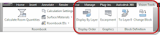
Four of the more popular tools that had been available to German, Austrian and Swiss subscribers have been made available to all AutoCAD® Architecture users. The Roombook ribbon tab from ACA 2013 has been renamed Vision Tools, and you will find these new tools there.
Display By Layer
The Display Order panel features one tool, Display By Layer, which runs the AecLayerOrder command.
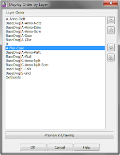
This tool allows you to rank the layers in a drawing and then have the display order set by the order in which the layers are ranked. This is a one-time deal. Future objects will appear on top of all previous objects; after setting the draw order by layer, that order is not dynamically applied to future objects. You can, of course, re-run the command, and the list is "remembered" with the drawing, so you do not need to recreate the list after saving, closing and then reopening the file. Note also that there is no way to "automatically clear" the draw order and return to what it was prior to applying this command. Two less-than-obvious ways this feature works involve external references. While you can re-order the layers of an external reference in the list and have it affect the display order, there are two limitations:
Escarpment
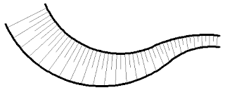
Use the Escarpment tool (AecEscarpment command) on the Graphics panel to create the linework often used to depict a sloping condition quickly and easily. You only need to pick the upper and lower sides and provide a distance between lines on the upper side. The generated linework is placed as a Block Reference, on the current layer; nested objects are on the current layer with ByBlock color, linetype, plotstyle (for drawings using named plot styles) and lineweight and ByLayer transparency and material.
To Layer 0
The To Layer 0 tool (AecMoveBlockToLayer0 command) on the Block Definition panel moves all nested objects within the Block Definition of a selected Block Reference to Layer 0. Unlike the Set Nested Objects to ByBlock option on the right-click menu when a block reference is selected (SetNestedObjectsByBlock command), this tool only changes the layer of the nested objects and leaves other attributes (color, linetype, plot style, and lineweight) alone. The SetNestedObjectsByBlock command also changes the color, linetype, plot style, and lineweight of the nested objects to ByBlock. The To Layer 0 tool also works on nested blocks, setting the objects within them to layer 0 as well; the SetNestedObjectsByBlock command does not affect objects within nested blocks.
Change Block
This tool runs the AecChangeBlock command, which allows you to select one or more Block References (which can have different Block Definitions) in the drawing and specify another Block Definition in the drawing for them. Insertion point, scale factors, layer, color, etc. remain unchanged. You have to type in the name of the new Block Definition. The command does offer a "?" option, which will list all of the Block Definitions in the drawing on the command line, for your reference.

Display By Layer
The Display Order panel features one tool, Display By Layer, which runs the AecLayerOrder command.

This tool allows you to rank the layers in a drawing and then have the display order set by the order in which the layers are ranked. This is a one-time deal. Future objects will appear on top of all previous objects; after setting the draw order by layer, that order is not dynamically applied to future objects. You can, of course, re-run the command, and the list is "remembered" with the drawing, so you do not need to recreate the list after saving, closing and then reopening the file. Note also that there is no way to "automatically clear" the draw order and return to what it was prior to applying this command. Two less-than-obvious ways this feature works involve external references. While you can re-order the layers of an external reference in the list and have it affect the display order, there are two limitations:
- Even though you can intermingle layers from an external reference with those of the host drawing and those of other external references, the net effect is to re-order the display of objects within the external reference relative to one another. All of the objects within a given external reference then are drawn relative to other objects based on the layer on which the external reference is inserted. For example, in the dialog above, even though the host layer A -Flor-Case appears in the list above the externally referenced layer BaseDwg|A-Wall, because the BaseDwg external reference is inserted on layer A-Anno-Refr (at the top of the list), all objects in the BaseDwg external reference will appear above objects on A-Flor-Case (or any other host drawing layer other than A-Anno-Refr).
- After saving a file with external references to which Display By Layer has been applied and then closing it, when you re-open the file, the display order applied to the layers in the externally referenced files is not automatically applied. The Layer Order list is remembered, however, so you can re-run the command to get the externally referenced layers order back to the way it was prior to saving/closing the file.
Escarpment

Use the Escarpment tool (AecEscarpment command) on the Graphics panel to create the linework often used to depict a sloping condition quickly and easily. You only need to pick the upper and lower sides and provide a distance between lines on the upper side. The generated linework is placed as a Block Reference, on the current layer; nested objects are on the current layer with ByBlock color, linetype, plotstyle (for drawings using named plot styles) and lineweight and ByLayer transparency and material.
To Layer 0
The To Layer 0 tool (AecMoveBlockToLayer0 command) on the Block Definition panel moves all nested objects within the Block Definition of a selected Block Reference to Layer 0. Unlike the Set Nested Objects to ByBlock option on the right-click menu when a block reference is selected (SetNestedObjectsByBlock command), this tool only changes the layer of the nested objects and leaves other attributes (color, linetype, plot style, and lineweight) alone. The SetNestedObjectsByBlock command also changes the color, linetype, plot style, and lineweight of the nested objects to ByBlock. The To Layer 0 tool also works on nested blocks, setting the objects within them to layer 0 as well; the SetNestedObjectsByBlock command does not affect objects within nested blocks.
Change Block
This tool runs the AecChangeBlock command, which allows you to select one or more Block References (which can have different Block Definitions) in the drawing and specify another Block Definition in the drawing for them. Insertion point, scale factors, layer, color, etc. remain unchanged. You have to type in the name of the new Block Definition. The command does offer a "?" option, which will list all of the Block Definitions in the drawing on the command line, for your reference.
April 10, 2013
ACA 2014: Door and Window Placement
Your requests have been heard. Prior to the 2011 release, when placing Doors and Windows, you had a choice between Unconstrained and Offset/Center, where the latter would center the Door or Window on a Wall segment if you click near the midpoint of that Wall segment or would offset the opening a user-set distance from the end of the Wall segment when clicking near that end. The 2011 release introduced a number of additional placement options, but in order to offer these, the Offset/Center option was split into two separate choices, Offset and Center. (Read more about this change in the 2011 release in a four-part series of posts starting here.) Many missed the convenience of having Offset/Center as a single choice and complained about lost efficiency in placing Doors and Windows. The 2014 release brings back the combined Offset/Center option

while keeping the options added in the 2011 release, as seen below on the Wall contextual ribbon tab, on the General panel.

In addition to restoring the combined Offset/Center option, you also now have options prior to placement for the justification of a Door or Window within the width of the Wall: in addition to the previous default initial justification of Center, you can now choose from Left and Right.

Where the Window is placed for Left or Right justification is determined the same way that Left and Right justification are determined for the Wall itself. Looking from the starting point of the Wall toward the end point, Left justification is to the left side of the Wall and Right justification is to the right side of the Wall.

If neither of these features gets your Door or Window placed exactly where you want it, the Reposition Along Wall and Reposition Within Wall tools are still available on the Door or Window contextual ribbon tabs or right-click menus, as well as the grip editing options.

while keeping the options added in the 2011 release, as seen below on the Wall contextual ribbon tab, on the General panel.

In addition to restoring the combined Offset/Center option, you also now have options prior to placement for the justification of a Door or Window within the width of the Wall: in addition to the previous default initial justification of Center, you can now choose from Left and Right.

Where the Window is placed for Left or Right justification is determined the same way that Left and Right justification are determined for the Wall itself. Looking from the starting point of the Wall toward the end point, Left justification is to the left side of the Wall and Right justification is to the right side of the Wall.

If neither of these features gets your Door or Window placed exactly where you want it, the Reposition Along Wall and Reposition Within Wall tools are still available on the Door or Window contextual ribbon tabs or right-click menus, as well as the grip editing options.
April 01, 2013
ACA 2014: Command Line Search
AutoCAD® Architecture 2014 expands upon the new AutoCAD 2014 feature that allows you to type in a few characters of a content item's name to initiate an "add" command for that content type, using that specific content. In ACA, this means you can add an instance of an object of a specific style or definition, just by typing in a few letters of the style/definition name, and then picking the style or definition from a list. This feature works on Curtain Wall Styles, Door Styles, Door/Window Assembly Styles, Railing Styles, Slab Styles, Space Styles, Stair Styles, Structural Member Styles, Wall Styles, Window Styles, AEC Dimension Styles, Schedule Table Styles, Zone Styles, AEC Polygon Styles, Mask Block Definitions and Multi-View Block Definitions. It will not work for Mass Element Styles or 2D Section/Elevation Styles.
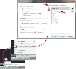
To determine if this feature is active, select the Customize tool (wrench icon) on the Command Line and choose Input Search Options from the context menu. In the Input Search Options dialog, verify that the Search content at command line toggle (top of right side) is checked, and, in the Content Type box, that the Architecture toggle is checked. You can control which AutoCAD content types are available through Command Line search using the other toggles in the Content Type area.
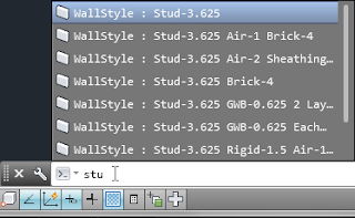
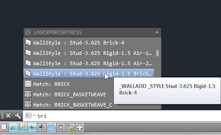
With the feature activated, simply type a few letters in the name of the style or definition for which you want to create a new instance, and a list will pop up above the Command Line. Depending on the number of types of object names and the number of names that match the typed string, you may get a list of style names, with or without a scroll bar.
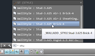
If you have tool tips enabled, you can hover over one of the choices on the list and see the entire command string that would be sent to the Command Line if you select that item.
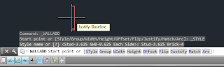
If you pick an ACA style/definition from the list, the appropriate "add" command is executed, and the style or definition is set to the one chosen. All other defaults are based on the last use of that command. See the Command Line for the next prompt or other options.
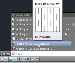
Depending upon what is typed and the names of both ACA styles/definitions and the names of AutoCAD content and command names, you may get a single line for the desired style/definition type, with a "+" (plus sign) at the right end.
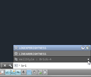
Select the "+" to expand the list and show all of the styles/definitions of that type, as well as any matching AutoCAD object styles, in this case, Walls Styles and Hatch patterns with "bri" in the name.
This new feature can speed up the process of adding an ACA object whose style/definition is already in the drawing where there is no identifiable instance on the screen to select and choose Add Selected from the contextual ribbom tab or from the right-click menu.
To determine if this feature is active, select the Customize tool (wrench icon) on the Command Line and choose Input Search Options from the context menu. In the Input Search Options dialog, verify that the Search content at command line toggle (top of right side) is checked, and, in the Content Type box, that the Architecture toggle is checked. You can control which AutoCAD content types are available through Command Line search using the other toggles in the Content Type area.

With the feature activated, simply type a few letters in the name of the style or definition for which you want to create a new instance, and a list will pop up above the Command Line. Depending on the number of types of object names and the number of names that match the typed string, you may get a list of style names, with or without a scroll bar.

If you have tool tips enabled, you can hover over one of the choices on the list and see the entire command string that would be sent to the Command Line if you select that item.

If you pick an ACA style/definition from the list, the appropriate "add" command is executed, and the style or definition is set to the one chosen. All other defaults are based on the last use of that command. See the Command Line for the next prompt or other options.

Depending upon what is typed and the names of both ACA styles/definitions and the names of AutoCAD content and command names, you may get a single line for the desired style/definition type, with a "+" (plus sign) at the right end.

Select the "+" to expand the list and show all of the styles/definitions of that type, as well as any matching AutoCAD object styles, in this case, Walls Styles and Hatch patterns with "bri" in the name.


This new feature can speed up the process of adding an ACA object whose style/definition is already in the drawing where there is no identifiable instance on the screen to select and choose Add Selected from the contextual ribbom tab or from the right-click menu.
March 26, 2013
ACA 2014: Property Set Defintion Auto-attach
AutoCAD® Architecture 2014 has a new feature that allows you to enable the automatic attachment of Property Set Definitions [PSDs] to objects. This setting is on a by-drawing basis, so you can have this turned on in some drawings and off in others.
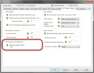
To turn on this feature, open the Options dialog and go to the AEC Object Settings tab. In the lower left corner, in the AEC Property Set Definitions area, clik the Automatically Attach toggle so that it has a checkmark. (Note also the drawing icon next to this item, indicating that this setting is saved in the drawing, and not in your Windows registry, so any change affects only this drawing.)
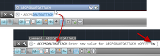
You can also use the AECPSDAUTOATTACH command at the Command Line to control this setting. ON or 1 enables the auto-attach feature; OFF or 0 disables it.
When Auto-attach is enabled, any existing PSDs in that file will be automatically attached to all objects or styles/definitions to which a specific PSD applies and to which the PSD had not been previously attached. When a new object is created, any applicable object-based PSD will be automatically attached; when a new style or definition is created or imported, any applicable style-based PSD will be attached.
Here are some observations and comments based on working with this feature:
To turn on this feature, open the Options dialog and go to the AEC Object Settings tab. In the lower left corner, in the AEC Property Set Definitions area, clik the Automatically Attach toggle so that it has a checkmark. (Note also the drawing icon next to this item, indicating that this setting is saved in the drawing, and not in your Windows registry, so any change affects only this drawing.)

You can also use the AECPSDAUTOATTACH command at the Command Line to control this setting. ON or 1 enables the auto-attach feature; OFF or 0 disables it.

When Auto-attach is enabled, any existing PSDs in that file will be automatically attached to all objects or styles/definitions to which a specific PSD applies and to which the PSD had not been previously attached. When a new object is created, any applicable object-based PSD will be automatically attached; when a new style or definition is created or imported, any applicable style-based PSD will be attached.
Here are some observations and comments based on working with this feature:
- While working outside of the ACA Drawing Management environment (Project Browser and Project Navigator), if you have a file ["File A"] with objects/styles that do not have certain PSDs that apply to those objects/styles attached, and you externally reference File A into a second file ["File B"] which has those PSDs in it and which also has Auto-attach enabled, the style-based PSDs in File B will be attached to the applicable styles/definitions in File A and the save time and date for File A will be updated. If style-based PSDs of the same name exist in File A (but were not previously attached to one or more styles/definitions), then the version in File A will be attached, even if it differs from the version in File B. If a style-based PSD of the same name does not exist in File A, then the style-based PSD will be copied from File B to File A. If there are no style-based PSDs in File B, or if there are style-based PSDs in File A with the same names and those are already attached to the styles/definitions in File A, then no action will be taken on File A.
- In the same scenario as Item 1 above, if there are style-based PSDs to be attached to objects in File A and if File A is from a previous file format, you will get a warning dialog and be given the choice to either proceed, saving File A in the current file format (2013, for ACA 2014) or to not save File A, discarding the "changes from this session" - in other words, not attaching the style-based PSDs in File A.

- In the same scenario as Item 1 above, the object-based PSDs in File B will be attached to the objects in File A, but only as property data overrides in File B. If those PSDs are later attached in File A, any values added there that are different from those in File B will not show in File B due to the property data override.
- In the same scenario as Item 1 above, if File A is open at the time it is being externally referenced into File B, the file lock on File B will prevent any style-based PSDs from being added to File A when Auto-attach is enabled. Once this fails, neither subsequent saving, closing or re-opening of File B nor moving the external reference instance within File B will trigger adding the style-based PSDs to File A. XATTACHing another instance of File A within File B will trigger another attempt to push the style-based PSDs to the File A.
- In the ACA Drawing Management environment (Project Browser and Project Navigator), the Auto-attach feature works the same way as noted above when working outside of it. I had expected that object-based PSDs being auto-attached to an object in an externally referenced Construct in a View file would have been attached at the Construct level, either directly on an object in the Construct, or as a property data override in the Construct to an object in a nested external reference (Element) within the Construct. That is how PSDs are treated when tagging an item through an externally referenced Construct in a View file.

Subscribe to:
Posts (Atom)