Showing posts with label Schedule Tag. Show all posts

February 28, 2021

AMEP: Plumbing Line "Label" with a Leader

A question came up the other day, concerning Plumbing Lines and the "Label Curves" that AutoCAD MEP provides to label those Plumbing Lines. The request was to be able to be able to label a short Plumbing Line - one shorter than the label itself - by offsetting the label and connecting the label back to the Plumbing Line with a leader.

The results of some quick research suggested that Label Curves do not have a leader option, when offset from the Plumbing Line that they are labeling. I am not sure if there is some inherent limitation here, or it just was never part of the specification for the object. They certainly have many useful features, like masking the Pluming Line, if desired, and repeating at a specified distance or a specified number of times - but no leader.

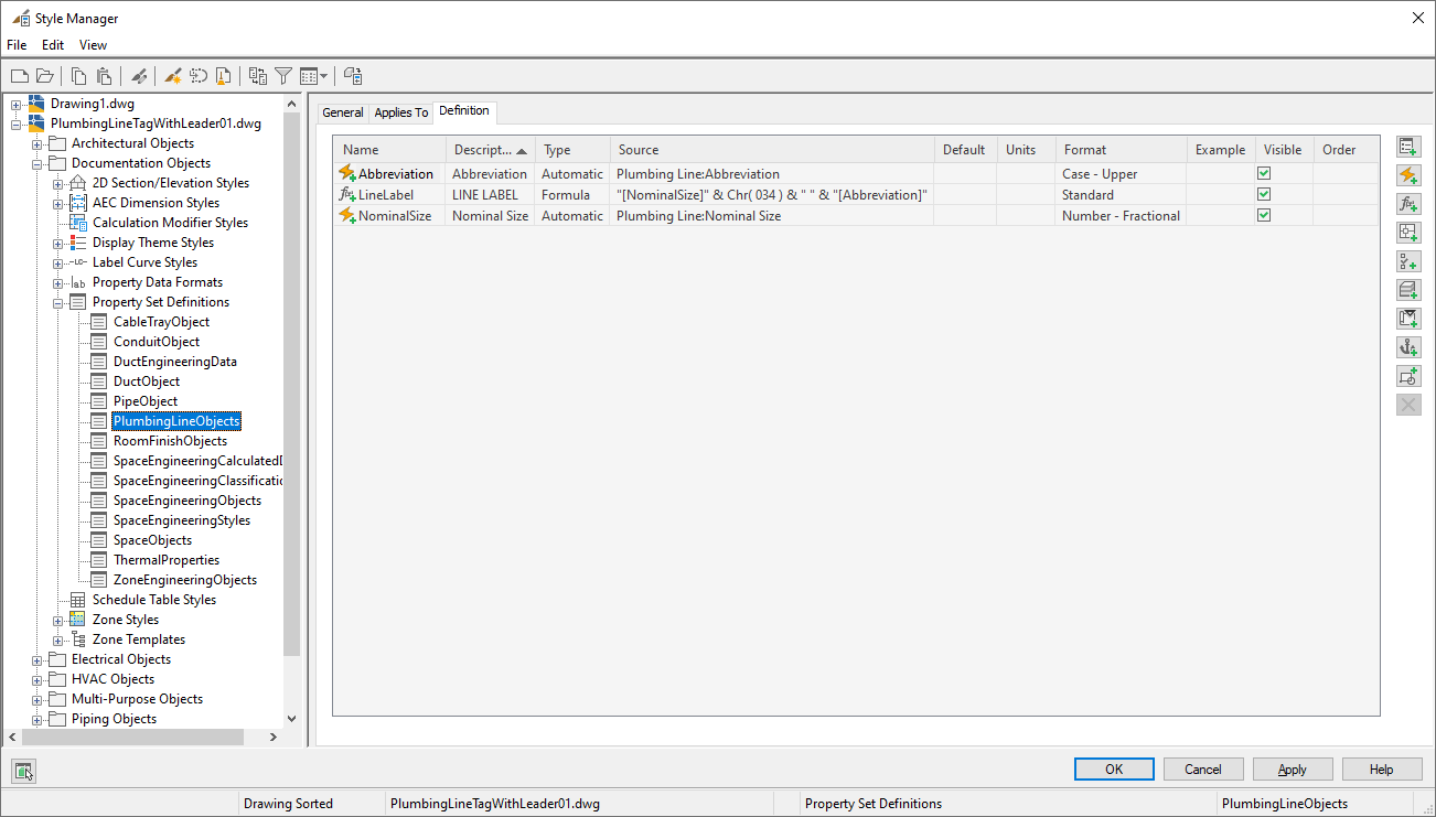
It occurred to me that, for the stated case of a short Plumbing Line, that the masking and repeating features were not necessary, and that a Schedule Tag, which can have an integral leader, could be created that looks just like the Label Curve, if the data displayed by the Label Curve was available in Property Data. It turns out that, at least for the Standard - Pipe With System Label Label Style, which shows the Object Props. and Abbr. System Name, Plumbing Lines have corresponding Automatic Property sources: Nominal Size and Abbreviation. I was able to create a Property Set Definition that applies to Plumbing Lines and includes three properties:
  • Abbreviation, created from the Abbreviation automatic property source. The Case - Upper Property Data Format was applied to this property.
  • NominalSize, created from the Nominal Size automatic property source. Since I was working in imperial units (it is one of my habits), I applied the Number - Fractional Property Data Format to this property.
  • LineLabel, a formula property, creates the string that is to be displayed in the Schedule Tag. It is a simple concatenation of the text equivalent of the NominalSize property, an inches symbol [via Chr(034)], a space and the Abbreviation property. The Standard Property Data Format was applied to this property.

A Schedule Tag can then be created to display the value in the LineLabel property, a Schedule Tag tool can be created for that Schedule Tag, the tool properties can be edited to include a leader and then the tool can be used to place a tag with a leader. The result can be seen in the image below, where the short Plumbing Line segment has both an offset Label Curve and a Schedule Tag with a leader, so you can compare the two.

July 11, 2019

ACA: Schedule Tag Background Mask

I suppose I must have known about this at some time in the past, but having never made use of it, it slipped my mind. The other day, I needed to make some Schedule Tags to replace some attributed Block References. The Attribute Definitions in the Block References had background masking turned on, so that they could be placed on top of other linework and the mask would assure that the contents of the attribute remained readable.

I made use of the graphics from the Block Reference and ran it through the DefineTag command to create the Schedule Tag Multi-View Block reference. I was hoping that the background mask on the Attribute Definition would be respected in the Schedule Tag, but it was not. An internet search turned up this Autodesk Knowledge Network Article, allowing me to re-learn what I had probably forgotten. You create an AEC Polygon Style to use for the background mask; on the Other tab, check the Use Background Mask toggle.

If you do not want the border of the AEC Polygon to plot, go to the Display Properties tab and create a Style Override for the Model Display Representation. In the override, turn off the visibility of the Exterior Edge component. (Do the same for the Model Screened Display Representation if you use that in views that include the Schedule Tags.)

Place an AEC Polygon instance using the Style you just created as part of the graphics you select for the DefineTag command. Be sure to select the AEC Polygon first, and then the other graphics, so that the other graphics are not masked by the AEC Polygon.

In the image below, the Door Tags have had a masking AEC Polygon placed behind the other graphics, and that AEC Polygon is masking out the color fill of the Space and the swing of the Door that is behind the Tag.

December 04, 2015

ACA: Underline in Tag But Not in Schedule III

This old post and this follow up post describe two ways to have a text property shown in a tag (such as a room name) be underlined in the tag, but not in a schedule table. The first post suggested adding a formula property, and concatenating %%u and the non-underlined property in the formula, and then using the formula property in the tag.

The second post accomplished the same thing by making a copy of the Property Data Format assigned to the text property and, in the copy, adding %%u in the Prefix field, and then assigning the new Property Data Format to the property in the Property Set Definition. When adding that property to a Schedule Table Style, the original, non-underlined Property Data Format would be used. The benefit of this method is that you do not need to make any changes to the view block used by the Schedule Tag's Multi-View Block Definition.

This all worked fine back in 2005/2006 when the articles were written, and for some time thereafter. I have not checked, but I suspect that the addition of multi-line attribute support for Multi-View Blocks (and, therefore, in Schedule Tags) in the 2009 release broke the recognition of %%u as a code to indicate starting (and stopping) an underlining of text. It certainly does not work in the 2016 release.

Fortunately, there is still a way to do this, and it can be used with either method. Just substitute \\L [the MText underline code] for %%u. For example, given a text property called Name, you could create a formula property that creates an underlined version of that property by using the formula
RESULT = "\\L" & "[Name]"
where "[Name]" is a properly created reference to the Name property.

Or, you could make a copy of the Property Data Format, such as Case - Upper, rename the copy Case - Upper - Underline, and add \\L to the Prefix property on the Formatting tab.

June 29, 2015

ACA: Classification Definitions, Applies To and Tagging

Classification Definitions have been around since Autodesk® Architectural Desktop 2004. One use for them is to act as an additional filter for the AEC objects that can be included in a Schedule Table; unlike layer filters, Classification Definition filters can be built right into the Schedule Table Style, on the Applies To tab. You can also use them on Property Set Definitions to limit the objects to which you can attach a Property Set.

I have been using them to control what objects are seen in Schedule Tables for quite some time now. A recent thread in the AutoCAD® Architecture General Discussion Group had me wondering if they could be used to prevent a Schedule Tag from being placed on an item, theorizing that if a Classification Definition was set up such that the Property Sets referenced by the Schedule Tag did not apply to a particular object, perhaps I would be unable to tag that object.

To test my hypothesis, in the 2016 release, I created a Classification Definition called Schedule that applies to all objects, with two Classifications: Schedule and No Schedule.

I then applied this Classification Definition to the Property Set Definitions referenced by the out-of-the-box US Imperial Door Tag (non-project), classifying each as Schedule.

Finally, I applied the Classification Definition to the Door Styles, on the Classifications tab of each style. In my test file, the Hinged - Single, Hinged - Double and Sliding - Double - Full Lite Door Styles were set to Schedule, and the Cased Opening Door Style was set to No Schedule.

I placed a few instances of the Doors (two of the Cased Opening style, one each of the others). On the Extended Data tab of the Properties palette, I observed that the Add Property Sets button was grayed out for the Cased Opening Doors, as it should be, since the DoorObjects Property Set does not apply due to the classification being set to No Schedule for those Doors. I edited the Cased Opening Door Style, and, on the General Tab, selected the Property Sets button and manually removed the FrameStyles, DoorStyles and ManufacturerStyles Property Sets (which were attached in the source file). Once I did so, the Add Property Sets remained grayed out, due to the classification.

At this point, I used the out-of-the-box US Imperial Door Tag tool (Document tool palette group, Tags palette) and attempted to tag each of the doors. As you can see in the image below, I was not prevented from tagging the Cased Opening Doors, even though none of the referenced Property Sets could be applied to those Doors. I did get a Command line message stating: Note: Not all properties apply to selected object. The DoorObjects Property Set was not applied to these Doors, and the Schedule Tag displayed the default value assigned to the attribute definition in the tag's view block. Surprisingly, the style-based Property Sets were attached to the Cased Opening Door Style, even though those did not apply, either.
In the image above, I turned on the display of the Anchor Extended Tag to Entity component, and set its color to green. The green arcs extending from the Schedule Tag insertion point to the Door origin point are these anchor components, verifying that the Tags on the Cased Opening Doors are in fact anchored. I also repeated this experiment, with a custom Schedule Tag that only referenced one object-based Property Set, but the Cased Opening Doors still received the tag, even though the referenced Property Set was not attached. Similar results were obtained in the 2015 release as well.

So, using a Classification filter to limit the objects to which Property Set Definitions apply will not prevent a Schedule Tag that references properties in such a Property Set Definition from being anchored, and will even add any style-based Property Sets referenced by the Schedule Tag. Object-based Property Sets will not be attached, and attributes that are set up to display the value of object-based properties will only show the default attribute value.

November 30, 2013

ACA: Offset External References, Location Properties and Schedule Tags

If you have ever externally referenced several files into one host file, and had Schedule Tags placed within the externally referenced files that displayed property values that were from or based on Location properties, you may have found that in the host file, the Schedule Tags did not display the expected values. One common example would be the use of a Door Tag that displays an ID value for the Door that is based in part on the associated room number, with the room number value being brought into the Door's properties via a Location property.

Depending upon what version you are using and how you place the external references, you may find that the values displayed in the tags all display values from the Spaces of one of the external references, or that you get *Space not found* in lieu of the Space-based property value that the Location property is supposed to be reading and which shows as expected when the externally referenced file is opened directly.

Things worked as expected in ACA 2009 and earlier, but some change made in the 2010 release affected the way that Location-property-dependent values are displayed in tags nested (placed) in the files that are externally referenced. All of the examples shown in this article are done outside of the Drawing Management feature (Project Browser and Project Navigator). Because managing property data overrides is difficult outside of the Drawing Management feature, tags referencing object-based properties are usually placed directly in the file that holds the object being tagged. (My firm does it this way, and from recent posts in the Discussion Groups, it appears that others do as well.) Note also that a Schedule Table placed in the host file that is set to scan external references and which uses the external references for the selection set and applies to the same objects that are tagged by the nested Schedule Tags will display the expected values in all of the releases from 2010 through 2014; the issue is only with the values displayed by nested Schedule Tags. In all releases since 2010, it appears that nested Schedule Tags do not look for a Space from the effective location of the nested Location grip in the host file, but instead take the relative X- and Y-distances from the insertion point of the external reference to the Location grip, and then apply that X, Y coordinate relative to 0,0 in the host file and look there for a Space (or, if your Location references a property attached to an AEC Polygon, for an AEC Polygon). If it finds a Space, it reads the specified property from that Space. That works fine for one external reference, inserted at 0,0. But in a file where you are inserting several external references, you will likely not place all of the files at 0,0,0, since then it would be up to ACA to determine which of what would likely be several overlapping Spaces would be used. Assuming that each floor of the floors is above or below the others (and that they share a common 0,0 point), all of the floors would be reading values from the Spaces in the floor placed at 0,0,0.

The logical solution would be to not place any of the external references in the host file at 0,0,0 and to place then such that the building footprint relative to 0,0,0 is left open in the host file. Unfortunately, in the 2010 and 2011 releases, that results in the tags displaying *Space not found* in lieu of the expected Space-based property value. I apologize to anyone still using the 2012 release, as I do not have access to an installed version of that release, so I am not certain how that release behaves. In the 2013 and 2014 releases, a partial adjustment was made, and the tags will display the value they display directly in the external reference file, provided that there is no Space at the "mapped" location relative to 0,0 in the host file.

I have posted some sample files, in the Door tag incorrectl​y finding informatio​n from other floors thread in the Autodesk AutoCAD® Architecture General Discussion Group, based on the "Room" shown in the image above, so that you can see the effects firsthand. There are three "floor" files, for the First, Second and Third floors, and a "sheet" file into which the three floor files are externally referenced. Each floor file has a single Space onto which two doors open. The files include a modified version of out-of-the-box DoorObjects Property Set Definition, in which two new properties have been added: RoomNumberNonProjectBased is a Location property, referencing the SpaceObjects:Number property attached to the Space; NumberRoomBased is a Formula property that concatenates the RoomNumberNonProjectBased property, a period (".") and the NumberSuffix property. The left-side doors have a NumberSuffix value of "1"; the right-side doors have a value of "2". The sheet file has a modified version of the out-of-the-box Door Schedule, with the MARK column deleted and replaced by a DOOR ID column, displaying the value of the NumberRoomBased property. The Doors are tagged in each floor file with a custom Schedule Tag that also references the NumberRoomBased property. The files were created in ACA 2010, so that they can be opened in that release or any later release.

The image below is of the sheet file, opened in 2010. None of the externally referenced floor files is inserted at 0,0, and there are no Spaces below the "mapped" location of the Location grips of the Doors.
Notice that the DOOR ID column in the schedule table correctly shows the values on all three floors, yet, as shown in the enlargement of the Second Floor external reference, the Schedule Tags inside the plan external references, which tag the doors, show *SPACE NOT FOUND* instead of the room number.

If the First Floor external reference is moved so that its insertion point is at 0,0,0 and the model is regenerated, then the nested Schedule Tags on the Doors on all three external references read the room number from the First Floor external reference. The Schedule Table continues to show the correct values, as seen in the image below.

If the First Floor external reference is moved back to its previous location, away from 0,0,0, and two Spaces (ROOM 5555 and ROOM 6666) are drawn in the host file, one at each mapped location and the model is regenerated, then the nested Schedule Tags on the Doors on all three external references will read the corresponding room numbers (5555 and 6666), but the Schedule Table will show the correct values, as shown in the image below.

Opening the same files in 2013 or 2014 will give the same results, with the exception of the first sheet view image above, where instead of *SPACE NOT FOUND*, the desired room numbers will be displayed on all three floor plans, because there is no Space in the "mapped" location.
November 25, 2009

ACA Scheduling by "Mark"

The out-of-the-box Door and Window Schedules and Schedule Tags are set up to identify each Door or Window with a unique identifier and list each one in the Schedule Table. While that suits many practices (including mine, for Doors), there are many who prefer to assign a "mark" to a particular Door or Window configuration and use that mark on all instances of that configuration. The Schedule Table would then list each mark only once. This is easily done in Autodesk AutoCAD® Archtecture, with the addition of a few properties and some tweaks to the Schedule Table and Schedule Tag you are using.

You can find a sample file done in the 2010 release (and, therefore, in the 2010 drawing format) posted in a reply in this thread in the Autodesk AutoCAD Architecture Discussion Group. The purpose of the sample file is to demonstrate a way of scheduling Doors by Mark, and the Property Sets, Schedule Table Style and sample data focus on that, and are not meant to represent a finished system, ready for use (or a compelling architectural design). Several other properties are included in the Property Sets and Schedule Table, to give a sense of context, but do not show all of the information you would want in a Door Schedule.

I made the following assumptions:
  • There would be a unique mark for each combination of Door parameters, including size.
  • Most Doors would be a "standard size" and that the mark for those Doors would be entered in the standard size description.
  • The system had to allow for an occasional, non-standard-size Door, without requiring that the Door Style of that Door be edited to have the non-standard size added.
  • An office-wide set of standard mark designations can be established and built into the office-standard Doors Styles, so that the standard sizes and associated marks do not have to be added to the Door Styles for each project.
If you have a unique Door Style for each mark you require, then a simple manual property in a style-based Property Set can be used to hold the mark value, add that to your tag and schedule and you would be done. If you can not establish office standards that will cover a large majority of the Doors on your projects, you may be better served with a manual property in an object-based Property Set and entering the value for each Door.

In the sample file, there are four Door Styles in which standard sizes have been entered and the desired mark has been assigned as the Description. The image below shows the Standard Sizes tab for the Single - Wood Full Flush - No Light Door Style.
There is an automatic property source for Doors, Standard Size Description, that will make the Description entered in for a Standard Size available in a Property Set. The DoorObjects2 Property Set in the sample file makes use of this for the MarkFromStdSize property. If you only use Standard Sizes, you can use this property directly in your Schedule Tag and Table. This property will display the value of the Not Applicable property of the assigned Property Data Format (NA for the out-of-the-box Case - Upper Property Data Format used in the sample file) if a non-standard size is used for a Door, so I included two additional properties: a text-type manual property (MarkOverride) to hold the value of the mark for non-standard-sized Doors and a formula property (Mark) to pass through the appropriate value for each Door.The Mark property is the one that appears in the tag and schedule. The MarkOverride property has a default value of EDITME, so that if a non-standard size is used and a MarkOverride value is not entered, it will be obvious in the tag or schedule.

The formula property checks the value of the MarkFromStdSize property. If it is "NA", then the value of the MarkOverride property is passed through; otherwise, the value of the MarkFromStdSize property is passed through. Note that in this example, changing the value of the override property is not the trigger for the formula property - the override value is only passed through when a non-standard Door size is used.
Add the Mark property to your Door Schedule Table Style, and delete any other "Mark" or "Door Number" column. To get all of the Doors with the same Mark to collapse into one row, add a quantity column to your Schedule Table Style. Hide this column if you do not want it to show in the final Schedule Table, as I did in the sample file.Keep in mind that for rows to collapse, all of the columns must show identical information. If you have an object-based Remarks column, such as the sample file has, you would need to add the exact same text the to Remarks property for each Door of a given mark for the rows to collapse. The same will hold true of any other columns in your Schedule Table.

The Door Tag in the sample file is simply a copy of the out-of-the-box Aec6_Door_Tag that has had the Multi-View Block and the assigned AutoCAD block renamed. The Attribute Tag of the assigned AutoCAD block was edited to reference/display the DoorObjects2:Mark property.

All of the Doors in the sample file are a standard size of their Door Style, except for the A4 Door, which is not and derives the "A4" mark from the MarkOverride property.

December 19, 2008

Non-Project Door Tag Using Room Number with Prefix and/or Suffix

If you are not using the Drawing Management feature (Project Browser and Project Navigator), you can still have room-number-based door numbers, and even allow for an optional prefix and/or suffix. You may have to do a little bit of setup, and create a custom Schedule Tag (or edit a copy of one of the out-of-the-box Schedule Tags), but it is really not all that hard, and the only thing that the Drawing Management feature brings (other than pre-made content) is the ability to have the room number prefixed by the Level property, which is an automatic project property. I will assume that you have dealt with that issue and have a way to assign your desired room number to each Space in a property in an object-based Property Set that is attached to each Space.

Making that room number property available to a Door is as simple as adding a Location property to an object-based Property Set that "Applies To" Doors. Location properties are best placed in object-based Property Sets. You can add one to a style-based Property Set, but unless the object already has another Location property in an object-based Property Set attached to it, the "Location grip" will not be generated and the Location property will not work. The Location grip, as seen below, is a four-pointed-star-shaped grip, that can be moved independently of the Door to which it is attached, and which will retrieve the specified property value from the first Space it finds below itself.

You can call for a Location property to return the value of any property that is in a Property Set that "Applies To" to a Space or AEC Polygon. (If you are using 2006 or earlier, Location properties also work with Area objects.) The Property Set of the referenced property must be attached to the Space or AEC Polygon in order for the Location property to return a meaningful value.

A prefix or suffix can be added by providing a manual property of the desired type. You can then display this value in a separate attribute in a Schedule Tag, as the out-of-the-box project-based Door Schedule Tag does, or by using a formula property to concatenate the prefix, room number and suffix into a single property. I have posted a sample file demonstrating how this could be done to this thread in the Autodesk Architecture Discussion Group. The DoorObjects2 Property Set in that file Applies To Door and Door/Window Assembly objects, and has the properties seen below. (Click on any image to see a larger version; use your web browser's Back button to return here.) SpaceNumber is a Location property that retrieves the SpaceObjects2:Number property that holds the room number. DoorNumberPrefix and DoorNumberSuffix are two manual properties that allow the user to add a prefix and/or a suffix to the room number value to create the final door number. The default value for each is an empty string. DoorNumber is the property that generates that final door number; it is a formula property whose formula is shown below. The formula checks the value entered into the DoorNumberPrefix property and, if it is an empty string, sets the variable doornumber1 to an empty string. If the user has entered a prefix value, doornumber1 is set to that prefix value with a period added as a delimiter, to visually separate the prefix from the room number. That part is not necessary, but some sort of delimiter may be desired if the nature of the prefixes and room numbers that you might be using could make it hard to tell if there is a prefix or not.

The formula then does a similar thing with the DoorNumberSuffix property, setting the variable doornumber2 to an empty string if a suffix was not added or to the concatenation of a period followed by the DoorNumberSuffix value, if a value was entered. Finally, the RESULT of the formula property is the concatenation of the doornumber1 value, the room number (from the SpaceNumber property) and the doornumber3 value. If no prefix or suffix is specified, then the room number is the final result, as seen at the Door in Conf 1007 in the sample plan below. The other Doors have a prefix, a suffix or both added to the room number, with the period delimeter separating any non-empty prefix or suffix from the room number.

If you want to see this in action, download and unZIP the sample file attached to my reply in the above-linked Discussion Group thread and try it out for yourself. The file was created in AutoCAD Architecture 2008, so you would need 2007 or later to be able to open the file.

November 15, 2008

Creating Annotative Tags in AutoCAD® Archtitecture

Annotative content, first added in the 2008 release, is a great feature, particulary for things like Schedule Tags – no more messing around with multiple view blocks and adding Display Representations/Display Representation Sets/Display Configurations to get a single tag to display at multiple scales. But, as you may have discovered, it can make creating a new tag, or even modifying an old one, and getting things the right size something of a challenge. Part of the confusion stems from the fact that AutoCAD and AutoCAD Architecture treat annotative content differently. AutoCAD will insert an annotative block using the current drawing scale’s scale factor to determine the final size; AutoCAD Architecture will use annotation scaling (as it did before AutoCAD added the annotative feature), a combination of the current drawing scale’s scale factor and the annotation plot size (specified on the Scale tab of the Drawing Setup dialog). Here is a method I use to make certain I get the Schedule Tag size I want, and it works whether I am drawing the graphics from scratch, inserting an existing Schedule Tag Multi-View Block and exploding it or directly inserting an existing view block and exploding it. It also works whether I use the Define Schedule Tag (AecDefineTag) or choose to build the Multi-View Block for my Schedule Tag manually.

Step 1: Set the Drawing Scale to 1’-0” = 1’=0” (or 1:1, for metric users) and the Annotation Plot Size to 1. In 2008, you can do both on the Scale tab of the Drawing Setup dialog. In 2009, you will need to set the Scale in the popup list on the Drawing Window Status Bar (or on the Application Status Bar, if you have the Drawing Window Status Bar turned off), since the Scale list on the Scale tab is only used to associate a Display Configuration with a scale, not to set the Drawing Scale.
Step 2: Create the graphics for your view block(s), keeping in mind that one unit in the block will plot at the Annotation Plot Size in effect at plot time. So if you want the property datum displayed in a particular attribute to plot at the Annotation Plot Size, make the attribute definition or text placeholder (if you are using the Define Schedule Tag wizard) one unit high. You can scale attribute definitions/text place holders up or down from one unit to get larger or smaller text in the tag, if desired. Draw any other graphics to suit. If you plan to start with the graphics from an existing Multi-View Block, you can insert an instance of it now, and it will be scaled in accordance with one unit plotting at the Annotation Plot Size, since the effective scale factor in 1 (Drawing Scale of 1 x Annotation Plot Size of 1). If you prefer to insert the view block of the tag directly, that too will insert at the proper size (Drawing Scale Factor of 1). Make the desired changes to the exploded content, or draw the desired graphics from scratch.

Step 3, Option A: Fire up the Define Schedule Tag wizard, select your graphics, convert any placeholder labels that are meant to display properties to have a Type of Property and assign the desired Property Set and Property to each. TIP: I like to to follow the out-of-the-box naming convention of using the Multi-View Block name with “_P” appended to it for the view block. The wizard will assign the same name to both the Multi-View Block for the Schedule Tag and the view block definition. I find it easier to use the view block name in the dialog, and then rename the Multi-View Block Definition in the Style Manager after it is created. Once you have everything set the way you want in the dialogselect the OK button, specify an insertion point for the Multi-View Block/view block, save the file and make a Tag tool by dragging the Multi-View Block to an editable tool palette. (For shared content, save the file as a source file in a location accessible to all, or copy the new Multi-View Block Definition to such a file, and then make the Tag tool from that file.) Set a Layer Key and make certain all of the other Properties of the Tag tool are as you desire, and you should be good to go. Reset the Annotation Plot Size back to your office standard, and set an appropriate Drawing Scale, and try out your new tag. It should come in at the expected size, and react to changes in Drawing Scale or Annotation Plot Size as expected.

Step 3, Option B: To use this option, you need to have attribute definitions with properly formatted attribute tags for each Property you want the Schedule Tag to show. Create an AutoCAD block definition for each view block you are going to assign to your tag. Fire up the Style Manager, create a new Multi-View Block Definition and add the view block(s) to the appropriate Display Representation(s) and then indicate the view directions for which each is to be visible. Exit Style Manager and save the file, or use Style Manager to copy the Multi-View Block Definition to a central source file and apply the changes. Create a Tag tool on an editable tool palette, set a Layer Key and make certain all of the other Properties of the Tag tool are as you desire, reset your Annnotation Plot Size and Drawing Scale and give it a try.

For a “simple” one-view-block Schedule Tag (as at least 90% of your tags will be, now that annotative content eliminates the need for multiple view blocks for multiple scales), Option A in Step 3 would be the way to go. Option B, on the other hand, may be useful if, for example, you have a space tag that needs to show different things for different drawing types – perhaps it shows the room name and area for schematic plans, room name and number for contract document floor plans and room name, number and ceiling height in reflected ceiling plans. Depending upon your workflow, it may be easier to have one tag that can do all of that than to have three separate tags. Of course, you could start out with Option A to get the first view block and the Multi-View Block set up, then add additional view blocks and adjust the Display Representations each block uses in the Multi-View Block as required.

May 01, 2008

Property Set Tools

While this feature was added way back in the 2006 release, I suspect that many are not aware of its existence. As you may recall, that release added Schedule Tag tools, providing an easier way to create and use Schedule Tags. Mastery of the AEC Content Wizard was no longer required!

One of the abilities of Schedule Tag tools is that you can specify additional Property Sets to be attached when tagging, even if those sets are not referenced by the Schedule Tag itself. Not only that, but you can also have the tool only add Property Sets, and dispense with the Schedule Tag altogether. An external source file can be specified to serve as the source of the Property Set(s), if the set(s) is(are) not already defined in the target file.

If you have ever wanted a tool that would attach Property Sets without adding a tag, simply make a copy of an existing Schedule Tag tool and edit the tool's properties. For example, in the 2008 release, I copied the out-of-the-box non-project-based Door Tag tool and pasted it on an editable tool palette.Right clicking on the tool and choosing Properties... from the context menu...
...opens the Tool Properties dialog, as shown below. This tool is a "Tag" type tool that currently does not add any Property Sets other than those referenced in the Schedule Tag, since the Property data property is empty.
If you left click on the Type property, you will get a pulldown menu with two choices: Tag and Property set data, as seen below. Change this from Tag to Property set data...
to have the tool attach Property Sets without adding a tag.
The tool you copied may point to a source file other than the one where your properties are kept. If so, simply left click on the Property def location property, and choose Browse... from the pulldown list.
This will open a standard file selection dialog that will allow you to navigate to the folder holding your source file and select that source file. With the proper source file chosen, left click on the Property data property, and choose the property or properties you wish to have the tool add from the Add Property Sets worksheet that displays. You can choose from both object-based and style-based Property Sets, keeping in mind that if you add a style-based set to an object, all objects of the same style will also have that Property Set added.
Select OK to register your choice(s), and then OK again to save the changes you made to your tool. Its as simple as 1, 3, 2 - and your tool is good to go. For a truly professional look, you may want to create a custom image file for your Property Set tool and add that to the tool (right click on the image in the Tool Properties dialog and choose Specify Image... from the context menu to specify the image file you created). Unlike tools that reference visible drawing objects, there is no "automatic" image for a Property Set only tool; the tool will retain the original image from the tag you copied unless you manually replace it with another image.

One feature I would like to see added is the ability to drag and drop a Property Set from Style Manager onto an editable tool palette to create a Property Set tool. Unfortunately, that is not possible in the 2008 release. Sounds like a good addition to the Wish List.

April 10, 2007

Multiple-Line Room Tags

There have been several recent requests for information on creating multi-line room tags in ADT/ACA. I thought I would collect the links I have been posting in a single article here, to make replying to future requests easier and to make certain I do not forget one or more of the resources.

Using Multiple Manual Properties to Enter the Room Name, And Then Combining Them in a Formula Property
This thread contains a sample file of an early version, done in ADT 2004, that supports two-line room names, from June 6, 2003. Download the sample from the file reposted on August 24, 2004.

In this thread, you will find a more clever formula, which supports three lines and could be easily expanded to even more lines, from January 25, 2005. That thread was also discussed in two blog articles, on July 4, 2005 and July 9, 2005.

Using a Single Manual Property to Enter the Room Name with MTEXT Codes, And Then Stripping the MTEXT Codes With a Formula Property
This Autodesk Knowledge Base article contains instructions on how to create a multi-line room tag using this approach.

Using a Single Manual Property [Driven by a List Definition in 2007 or Later], an Index Number and Multiple Formula Properties
Tomaslav Zigo posted this article to his blog showing a way to have a two-line room name tag populated from a single source and split at a user designated place without the need to type in MTEXT codes. This allows the use of List Definitions for the room name [and index] in 2007 and later, contrary to this previous post.

Multi-Line Attributues
Unfortunately, the new multi-line attributes added to AutoCAD® 2008 are not active when incorporated into a view block of a Multi-View Block Schedule Tag in AutoCAD® Architecture 2008. Here is hoping that feature makes its way into next year's release, so that a single attribute that does not need to be repostitioned can display multi-line room names and eliminate the need for fancy formulas.

April 06, 2007

Annotative Tags With Leaders in ACA 2008

The image above shows three interior walls drawn in AutoCAD Architecture 2008, with the out-of-the-box wall tag applied. Like all of the tags in 2008, the wall tag makes use of the new annotative scaling, as does the leader that is drawn as part of the tag tool function. These were created with the annotation scale set to 1/8" = 1'-0", as can be seen on the Drawing Window Status Bar. [Click on the image to see a larger version.] So, what happens when you change the annotation scale?
The image above shows the annotation scale being changed to 1/4" = 1'-0".
As you might expect, the tags have reduced to half of their size at 1/8" = 1'-0", maintaining their insertion points. The "arrow head" on the leader has also reduced in size by 1/2, but notice that the tag end of the leader remains stubbornly in the same place it was when it was created for the 1/8" = 1'-0" size of the tag, leaving a gap between leader and tag at 1/4" = 1'-0". Ideally, the leader end would have adjusted to the change in the tag.
Hovering over the leader of the A2 tag, as seen in the image above, causes the annotative icon to appear above and to the right of the cursor. The icon looks like the ends of two three-sided scales.
The end of the leader at the A2 tag has been grip edited to extend the end to the midpoint of the top of the tag at 1/4" = 1'-0". But will that also change the endpoint at 1/8" = 1'-0"?
As you can see in the image above, when the annotation scale is changed back to 1/8" = 1'-0", the end of the leader at that scale remains in its original position, and if you were to change it back to 1/4"=1'-0" again, the edit at that scale will be "remembered," as seen below.
So, while the leader end at the tag will not automatically move to maintain its relative position at the surrounding graphics of the tag as the tag changes sizes for different scales, you can manually edit the leaders and the endpoint location will be retained separately for each scale. This behavior applies to all leaders that have an annotative Dimension Style, which will come in handy when placing a room tag outside of a small room. You can now use a single leader on a single layer and have it work for every scale at which you will show the tag, with a little work to edit the leader endpoint to work with each scale.

March 03, 2007

Adding a New Scale to a Scale-Dependent Block

This post may become irrelevant once everyone has migrated to AutoCAD Architecture 2008 or later, but I suspect that may be some time from now, given the pace at which some firms (even those on subscription) deploy new releases. Here is the situation – you are using a scale dependent tag that is set up the way that the out-of-the-box tags are set up, with three possible scales supported by view blocks assigned to the Plan Low Detail, Plan and Plan High Detail Display Representations in the Multi-View Block tag. The out-of-the-box content is set up for these to work at 1/16" = 1'-0" or 1:200, 1/8" = 1'-0" or 1:100 and 1/4" = 1'-0" or 1:50. But suppose you have a project where you need to show those very same tags at a different scale? If I were working in Project Navigator, I would create a single-scale tag, set up a new View file and retag the space with the single-scale tag, scaled for the scale I needed. Tagging across external reference files outside of Project Navigator is not quite so simple, unless you never expect to make changes to the data displayed by the tag, and particularly if you are using an older version of Autodesk Architectural Desktop. One way around that would be to add "another scale" to the scale dependent tag. Here is what you would need to do; you can decide if it is worth the effort.

My apologies to the rest of the world working in metric units, but being more familiar with imperial units, the example here will use those. The same principles and techniques will apply to metric units, just adjust the sizes and scale references to the appropriate metric values.

This tutorial will show the changes needed to add a 1/32" = 1'-0" view block to a scale-dependent room tag. The tag is a modified version of the Autodesk Architectural Desktop 2004 out-of-the-box tag found in the Room Tag – Project Based – Scale Dependent AEC Content file. The modifications consist of changing the room number attributes to reference the RoomObjects:Number property instead of the project-based RoomObjects:NumberProjectBased property, then giving the view blocks and the Multi-View Block different names so that there will be no conflict with the out-of-the-box tag's view blocks and Multi-View Block. In order to add a new tag scale and be able to display just that scale, we will need to create a new Display Representation for Multi-View Blocks to which we can attach a newly created view block, scaled for 1/32" = 1'-0". That Display Representation, in turn, will need to be turned on in a new Display Representation Set (and the existing three scale-dependent Display Representations turned off). A new Display Configuration that shows the new Display Representation Set when the Top view direction is current completes the changes to the Display System. The final step will be to create the new view block and assign it to the Top and Bottom view directions of the tag's Multi-View Block Definition. Note that this provides scale-dependent support just like the out-of-the-box setup. If you have added scale-dependent support for other types of drawing, such as reflected ceilings or for non-plan views, then you would need to repeat the procedure to support the new Display Representation in those other drawing types, as well. One final note: the images here are from Autodesk Architectural Desktop 2004, run on the Windows 2000 operating system. If you are running a later version or using a different operating system, your dialogs, menus and operating methods may be slightly different.

  1. Start a drawing with an appropriate template file and open the Display Manager. One way to do this is to select Format > Display Manager… from the pulldown menus. Expand the Representations by Object folder in the left pane, then select Multi-View Block Reference. You should get something that looks like the image below. You can see a larger version of reduced-size images by clicking on them.

  2. Right click on the Plan Low Detail Display Representation in the right pane, and choose Duplicate from the context menu.

  3. Select the duplicated Display Representation, right click and choose Rename from the context menu. Give the Display Representation a meaningful name. The out-of-the-box names were specifically designed to avoid association with a specific scale. You may want to continue with that and name your new Display Representation "Plan Very Low Detail". If you only expect to add one or two additional scales or need to support both imperial and metric units, that may work for you. Since the Display Representation I am creating is associated with a specific scale and I want to allow for adding many additional scales, I chose to make the name in this example scale-specific, and called the new Display Representation "Plan Detail 0384". (1/32" = 1'-0" is 1:384.) Do not check any of the boxes to the right of the new name, as we will need to create a new Display Representation Set for our new Display Represenation. Click on the Apply button in the lower right corner of the Display Manager dialog to register the change you just made to the drawing file. That will prevent a mis-timed hitting of the Esc key from wiping out your new Display Represenation. If you are really paranoid (or prudent), click OK in the Display Manager and save the file, then reopen the Display Manager.

  4. Expand the Sets folder in the left side of the Display Manager and select the Plan Low Detail Display Representation Set. The right pane will show three tabs: the General tab allows you to edit the name and description; the Display Representation Control tab shows a matrix of objects and the Display Representations, with boxes indicating which Display Representations are available for each Object type and checked boxes indicating which of those are turned on or active for the selected Display Representation Set; and the Display Options tab allows you to set up Classification filters and set Live Section parameters. The Display Representation Control tab will eventually be of interest, so if that tab is not currently displayed, click on it so that it is. Right click on the Plan Low Detail Display Representation Set in the left pane and choose New from the context menu. Give the new set a meaningful name; I chose to use "Plan Detail 0384" again. If you were paying close attention, you will notice that the new set has the exact same boxes checked as the selected set. Plan Low Detail was chosen for this example because it is closest to what I want to show in the new Display Representation Set. If the new scale to be added were 1/2" = 1'-0", I would have started with the Plan High Detail Display Representation Set. When adding a new scale for your own work, choose the most appropriate existing set before making your new one. You can create a new set with no Display Represenations selected by right clicking on the Sets folder and choosing New – but unless your new set will be totally unlike any of the existing sets, it is generally easier to start with one that is close and edit to suit.

  5. With the Plan Detail 0384 set selected in the left pane, select the General tab and change the description to "1/32" = 1'-0" display detail". Now select the Display Represenation Control tab and find the Multi-View Block Reference line in the right pane. You may need to scroll down, depending upon your monitor size and resolution and the size of your Display Manager dialog. Leave the General Display Representation checked – that will allow non-scale dependent Multi-View Blocks, such as furniture, equipment or fixtures, to display when the new set is active. Uncheck any scale-dependent Display Representations, in this case, Plan Low Detail, and add a check in for our newly added Plan Detail 0384 Display Representation. You may need to scroll to the right to see these. Hitting the Apply button now may be a good idea. If you want, you can select Multi-View Block Reference under the Representations by Objects folder and note that the Plan Detail 0384 Display Representation now has a check mark for the Plan Detail 0384 set.

  6. Expand the Configurations folder and select the Low Detail Display Configuration. Right click and choose New from the context menu and give the Display Configuration a meaningful name; I used "Detail 0384". Similar to what happened when we created the Display Representation set, our new Display Representation is a copy of the selected one; choose the one closest to your desired final settings or right click on the Configurations folder to create a new Display Configuration with the default settings of Plan for the Top view and Model as the Default view. With Detail 0384 selected in the left pane, choose the Configuration tab and change the Display Representation Set assigned to the Top view direction from Plan Low Detail to Plan Detail 0384 by clicking on Plan Low Detail in the right pane and choosing Plan Detail 0384 from the dropdown list. As before, the General tab can be used to edit the Display Configuration's name and description – I changed the description to 1/32" = 1'-0" Scale Plans. The Cut Plane tab allows you to set the cut plane and specify above and below ranges for the display. I chose to leave these values as they were set for the Low Detail Display Configuration.

  7. That is all we need to do in the Display Manager. If you want other objects to display differently at the new scale, then you could make additional changes, but that is beyond the scope of this tutorial. Select OK in the Display Manager, save and close your file. The next step will be to add a new view block to the Multi-View Block used by your tag. Where to do this will depend upon what version of Autodesk Architectural Desktop you are using. In 2005 and earlier, you will need to have your tag setup in an AEC Content file. Users of 2006 and later will find the out-of-the-box scale-dependent tags in the same source file as the other tags, but as discussed in a previous article, to get scale-dependent tags to work properly, you really need to have an AEC Content file, too. See that previous article for a way to set that up in 2006 or later. I would suggest making a copy of any existing content file and making your changes there, until you are certain that it is "ready for prime time". I also strongly recommend renaming the Multi-View Block and the view blocks when modifying existing content to avoid conflicts in drawing files that already have the old Multi-View Block or any of the old view blocks already definined within. It does require a little bit of extra work beyond the renaming in that you need to edit the file in the Create AEC Content Wizard to add the new names to the content file and put the correct Multi-View Block name in the custom command string, but in the long run it is worth that one-time effort. I am going to assume that you have a working AEC Content file that is the equivalent of one of the out-of-the-box scale-dependent tags. The following describes how to add the fourth scale, as we set up with the changed made in the Display Manager above.


  8. The first thing we need to do is to get our new display settings into the AEC Content file. If your content file is not already in a folder that is included in the AEC Content folder structure for your current profile, you will want to put it there now. The AEC Content folder structure consists of the folder specified for the Content Path on the AEC Content tab of the Options dialog, all subfolders under that, and any other folders included by Windows shortcuts that are included in those folders. For your tag to work correctly, you will also need to have the source file for the Property Set Definitions referenced by the tag in either the same folder as the tag or the folder above the tag's folder. If you are working on a copied file in a folder referenced by a Windows shortcut, you may need to put a copy of that Property Set Definition source file in your test folder while creating and testing the content. NOTE: If your office has their office-standard AEC Content in a read-only network directory, as mine does, and you do not have write access to those folders, you may have to ask whomever is in charge of the content if they would kindly add a Windows shortcut to a folder present on every user's hard drive so that you can develop new content files locally. My office has done this; a shortcut called "Local AEC Content" points to "C:\Documents and Settings\All Users\Application Data\Autodesk\Autodesk Architectural Desktop 2004\R16.0\enu\AEC Content", which happens to be the default location for AEC Content for a stand-alone installation. You do not need to use this location; any folder to which you have write authority will do.


  9. With all that in place and your tag's AEC Content file and the Property Set Definition source file in the same folder or the folder above, open DesignCenter and navigate to the folder holding the tag's AEC Content file. The image below shows this on my computer, which has a lot of other test tags that have accumulated over the years. Select your tag file, right click, and choose Open from the context menu.

  10. Users of 2004 and 2005 should make certain that you saved and closed the file in which you made the new display settings in steps 1 through 7 above – if the file is still open, you will not be able to use the Import/Export Feature. Open the Display Manager, right click on the Configurations folder, and select Import/Export… from the context menu.Users of 2006 and later can either leave the file with the new display settings open in ADT or open it inside Display Manager, then drag the Detail 0384 Display Configuration from that file to the AEC Content file in the left pane to transfer the new display settings. Check to see that the new Display Represenation Set and Display Representation for Multi-View Block References also transferred, then select OK, save your file and skip ahead to Step 12. (Upgrading is good!) Users of 2004 and 2005 will need to continue with Step 11.


  11. Select the Open… button in the Import/Export dialog, and navigate to the file in which you created the new display settings. Choose the new Display Configuration in the External File list box, Detail 0384 in the example here, and select the <<< Import button to bring that Display Configuration into the AEC Content file. This will also bring in the new Display Representation Set and Display Representation; the latter will be needed when adding the new view block to the Multi-View Block Defintion. Select OK to accept the addition and dismiss the Import/Export dialog. Note that in 2004, the Medium Detail Display Configuration also transferred over. I deleted that by expanding the Configurations folder in the left pane, selecting Medium Detail, right clicking and choosing Delete from the context menu. If you like, you can expand the Representations by Object folder and select the Multi-View Block Reference item, to see that the Plan Detail 0384 Display Representation has been added. Select OK to accept the display changes made and save the drawing file.

  12. The file should have some graphics in model space, which form the basis of the icon that can be automatically generated for the AEC Content file. In 2005 and earlier, this would be the medium detail block in the out-of-the-box content files. For our example, we will need to insert an instance of the low detail view block, which in my case is called "Aec4_Room_Tag_NoProject_LoDtl_P". If you are uncertain which is the low detail block, you can open the Style Manager and edit the Multi-View Block Definition to find block assigned to the Plan Low Detail Display Representation. I am choosing this block as it is closest in size to my new block. Any of the blocks would do – or you could create a new block from scratch, which may be desirable if the graphics for the new scale are to vary from those for the other scales. If you are going to use the medium detail block, insert a new instance or copy the one already there, rather than messing with the existing instance and having to replace it. Either insert the block at a known point or draw a line with one endpoint at the insertion point, for easy reference when defining the new block.

  13. Explode the Plan Low Detail block, and then scale all of the objects from the exploded block by a factor of 2, using the block insertion point as the base point. This will get the graphics at the right size for 1/32" = 1'-0" when starting with graphics meant for 1/16" = 1'-0". In your own work, use the appropriate scale factor based on the scale of the starting graphics and the final intended scale.

  14. Define the new view block, using the rescaled objects and the original insertion point. I called my new block "Aec4_Room_Tag_NoProject_0384Dtl_P".

  15. Save your file, then erase the redefined block and the reference line (if you added one), leaving only the original graphics in model space. I like to ZOOM Extents at this point, both to get the remaining graphics to fill the screen and to be certain I did not leave anything extra in model space. Open the Style Manager (Format > Style Manager… is one way to do so), expand the Multi-Purpose Objects folder and expand the Multi-View Block Definitions item under that. Select the Multi-View Block for your tag (it should be the only one), right click and choose Edit… from the context menu. On the View Blocks tab, you should find that the previously existing blocks are assigned to the Top view direction for the Plan, Plan High Detail, Plan Low Detail and Reflected Display Representations. Select your new Display Representation, Plan Detail 0384 in the example here, in the Display Representations list box on the left.

  16. Select the Add… button and choose the newly created block, "Aec4_Room_Tag_NoProject_0384Dtl_P", from the Select a Block dialog. Uncheck all of the view direction toggles except for the Top view direction. Select OK twice to save the edits to the Multi-View Block and to exit the Style Manager. Save the file.

  17. At this point, I like to run the PURGE command to clear out any excess baggage, so that does not get carried over into every file when using the content file. After doing so, you may want to have a quick look at the items you can not purge, too. If there are extra blocks or layers, you may want to go back into the Display and Style Managers and delete any "extra" Display Representation Sets and Display Representations that may have been imported or any "extra" styles or definitions that may be in this file, then run the PURGE command again to get rid of any items that can now be purged. Save and close the AEC Content file.


  18. Back in DesignCenter, select your AEC Content file and choose Edit… from the context menu to call up the Create AEC Content Wizard. In the Current Drawing list box, select the name of the newly created view block - "Aec4_Room_Tag_NoProject_0384Dtl_P" – and select the Add >>> button to add it to the content file. The Content File list box should contain the names of all of the view blocks and the name of the Multi-View Block for the tag. If you renamed the view blocks and the Multi-View Block as suggested in Step 7 above, but have not yet edited the AEC Content file to include the renamed blocks/Multi-View Block, now would be the time to add them and then edit the Command String to show the Multi-View Block name after "SYMBOL" in the command string.

  19. Select the Next > button and inspect the settings here. Unless you want to change anything – and you do not if the tag is to work like the original one did, select Next > again. You may want to check the Detailed Description and make any changes to distinguish this content file and verify that the Icon is acceptable. Select Finish to save the changes made to the AEC Content file. You now have a scale-dependent tag with four different scales. Test out the tag in the file in which you created the new display settings. When you are satisfied that it works properly, you will want to get the new Display Configuration imported into your template file(s) as well as in any existing files in which you want to use the new tag, so that the added view block can be seen.