Showing posts with label Window. Show all posts

April 10, 2013

ACA 2014: Door and Window Placement

Your requests have been heard. Prior to the 2011 release, when placing Doors and Windows, you had a choice between Unconstrained and Offset/Center, where the latter would center the Door or Window on a Wall segment if you click near the midpoint of that Wall segment or would offset the opening a user-set distance from the end of the Wall segment when clicking near that end. The 2011 release introduced a number of additional placement options, but in order to offer these, the Offset/Center option was split into two separate choices, Offset and Center. (Read more about this change in the 2011 release in a four-part series of posts starting here.) Many missed the convenience of having Offset/Center as a single choice and complained about lost efficiency in placing Doors and Windows. The 2014 release brings back the combined Offset/Center option

while keeping the options added in the 2011 release, as seen below on the Wall contextual ribbon tab, on the General panel.


In addition to restoring the combined Offset/Center option, you also now have options prior to placement for the justification of a Door or Window within the width of the Wall: in addition to the previous default initial justification of Center, you can now choose from Left and Right.

Where the Window is placed for Left or Right justification is determined the same way that Left and Right justification are determined for the Wall itself. Looking from the starting point of the Wall toward the end point, Left justification is to the left side of the Wall and Right justification is to the right side of the Wall.


If neither of these features gets your Door or Window placed exactly where you want it, the Reposition Along Wall and Reposition Within Wall tools are still available on the Door or Window contextual ribbon tabs or right-click menus, as well as the grip editing options.

September 08, 2012

ACA: Grip Editing of Doors and Windows with Standard Sizes

One nice feature of AutoCAD® Architecture is that you can assign standard sizes to Doors and Windows. This allows the user to select a standard size from a list of the sizes entered into the Style, saving time and minimizing the potential for error.
Better still, when grip editing an instance of a Style with standard sizes, the inital default is to restrict the grip edit to one of the values that is part of a standard size. Does that mean that you cannot use such a style to create a non-standard size Door or Window? No. You can always use the Properties palette to enter a non-standard Width or Height. But you can also use grip editing to do so.

Given the wide range of things that grips on AEC objects can do, I highly recommend turning on grip tips, if you do not already have them on. Check the toggle in the Grips area on the Selection tab of the Options dialog or set the GRIPTIPS system variable to 1.
With grip tips enabled, if you select an AEC object and hover over a grip, you will get a tip on how that grip can be used. In the image below, a Window has been placed, using one of the standard sizes assigned to its Style. The Window has been selected, and the cursor is hovering over the grip, but the grip has not been selected (made "hot") yet.
The first line of the grip tip (yellow box) indicates that the Width and Height of this Window are currently a standard size*. The rest of the tip tells you that you have two options when using this grip - either stretching to a Standard Width (the initial default, as it is first on the list) or to a Custom Width - and that you can toggle between the two by pressing the CTRL key. If you start with a Window that has a Width and Height which are not paired as a standard size, the grip tip is nearly identical, with the exception that the first line indicates that the Window is currently a Custom Width*. The initial default remains to stretch to a Standard Width.
Many AEC grips have more than one state or function, and the tip provides a handy reminder of what those are and how to activate them. In general, the CTRL key is used to toggle through the available options.

When you first make the grip hot, you will be restricted to stretching the grip to a standard Width, as defined in the Style. ACA will display a series of lines, indicating the places to which you will be permitted to stretch the Window or Door. You can stretch to any Width that is part of a standard size, even if it is not paired with the current Height as a standard size. To show this graphically, "long" gray lines are used to indicate Widths that are paired with the current Height in a standard size, and "short" red lines are used to indicate Widths that are part of at least one standard size, but which are not paired with the current height in one. A grip tip will appear to remind you of this, if grip tips are active.

If you press the CTRL key once after making the grip hot (but before left clicking to select a stretch point), you will be able to stretch the grip without any restriction.

* - Unfortunately, if the current Window Width and Height are not a standard size, the tip for the Width grip will read "Custom Width", even if that Width does appear in the standard size list, paired with a different Height. The tip really should read "Standard Size" or "Custom Size", to be less confusing. NOTE: Images in this post were made using ACA 2010. Other versions may have slightly different graphics or text.

March 22, 2011

ACA 2012 New Feature - Corner Windows


One of the new features added to AutoCAD® Architecture 2012 is one for creating corner windows. An easy way to do so has been on the wishlist for some time, and now it is here. Corner Windows make use of "regular" ACA Window Styles, which now feature some added properties on the Dimensions tab in the Frame area.As you can see in the image above, you have the option of specifying butt glazing at the corner. If this toggle is unchecked, you will get a frame at the corner, and you can specify the exposed inside width of the frame (dimension "K"). Window Styles from previous releases will default to having the Butt Glazing at Corner toggle checked (K - Width of 0). The out-of-the-box "regular" Window Styles also have the Butt Glazing at Corner toggle checked. While there is no reason to create a separate Window Style with "Corner Butt Glazing" in the name, the out-of-the-box content includes a "Corner Butt Glazing - Picture" Window Style that is used by the Tool palette tool of the same name.
Corner Windows are placed using a new command, WINDOWCORNERADD. You can create your own Corner Window Tool palette tool by copying one of the out-of-the-box tools and modifying the properties to use your desired style. In addition to the out-of-the-box style-specific tools on the Corner Windows palette in the Design Tool Catalog (under Doors and Windows), you can find a generic Corner Window tool in the Stock Tool Catalog, under Architectural Object Tools. You can also invoke the WINDOWCORNERADD command on the Home ribbon tab, on the Build panel, by clicking the down arrow icon at the right side of the Window split button and choosing the Corner Window tool.
Corner Windows must be placed by selecting a Wall; they can not be inserted as free-standing objects, like "regular" Windows. The Wall selected must also be intersected by another Wall, and both must clean up to form an "L" corner; the angle need not be 90 degrees. "T" or "X" intersections will not work. Curved Walls are also not currently supported. If you try to place a Corner Window and nothing happens when you select a Wall, check the Command: line for helpful messages such as "No valid wall intersection found for selected wall." to help you figure out why the Corner Window is not being placed.
After selecting the first Wall, a preview of the Corner Window will appear on screen. If there are valid corners at each end, you can move your cursor closer to the desired end to have the preview appear at the correct end. When adding a Corner Window, you will find that instead of being able to edit the usual Width property (Dimension A, which is still there, but not editable), you now have two new properties, Width 1 (Dimension E) and Width 2 (Dimension F), which allow you to control the width of each leg of the Corner Window. Width 1 applies to the leg within the selected Wall, Width 2 applies to the other Wall. The Width property will display the sum of the Width 1 and Width2 values.In the image above, the horizontal Wall was selected, and the dynamic dimension for Width 1 is initially active. You can set the widths using the dynamic dimensions or by editing the properties on the Design tab of the Properties palette. Use the Opening measure property to choose whether the specified Width 1 and Width 2 values are measured to the Outside of opening, Center of opening or Inside of opening.
Standard Sizes remain the same as before - when placing a Corner Window, the width dimension specified is used for both legs.

Corner Windows can be tagged and scheduled just like "regular" Windows". The Width automatic property source will show both widths, separated by " x ".
Corner Windows can be grip edited similar to "regular" Windows, with some Corner-Window-specific changes. The arrow-shaped Flip grip located at the jamb will swap the Width 1 and Width 2 legs. This does not just swap the width values, but actually moves the Width 1 leg to the other Wall, as if it had been selected first. The square Location grip offers a different first option. Instead of "Move along" Wall, which makes no sense for a Corner Window, it offers "Specify wall corner", which allows you to move the Corner Window to any other valid "L" corner Wall intersection, even one involving two different Walls.
Cautions

Corner Windows should not be used in projects where any other team members are not on the 2012 release. While ACA 2012 uses the AutoCAD® 2010 file format and ACA 2010 and 2011 will be able to open the file, neither of those releases will support the proper display of Corner Windows and you will get a "regular" Window, with the width equal to the sum of the center of opening values of Width 1 and Width 2, anchored to the Width 1 Wall at the time it was saved in 2012 and hanging over the end of the Wall, as seen in the image below.Schedules created in 2012 with Corner Windows will also show undesired results when opened in 2010 or 2011. (The Width column will show like a formula property with an error, displaying the entire formula used to calculate the Width value.) In limited testing, it appears that opening/editing/saving in 2011 and reopening in 2012 causes no harm, but you will want to test that in your own environment and with the sorts of edting you expect to do before relying on it being safe.

The openings created by Corner Windows are not taken into consideration when using the Offset or Center options when placing other opening objects (Doors, Windows, Openings, Door/Window Assemblies) in a Wall that has a Corner Window. This is not the behavior I expected, so you will want to keep that in mind.

Any type of Window Style can be used as a Corner Window, but it may not be appropriate for all types. For example, you can set up a butt-glazed Glider Peak Corner Window, but that does not mean you should (nor does it mean it could be built).

December 11, 2010

Displaying Windows Above the Cut Plane in ACA

Over the years, there have been a number of requests in the Autodesk Discussion Groups and the AUGI Forums on how to get a Window that is above the global cut plane to display in a plan view (Top view direction). There are a number of approaches to this, and which one you should use depends upon how you want to see the Window and whether any particular change has unwanted side effects. For the purposes of this investigation, I am going to assume that the Window in question really is meant to be above the global cut plane and is not simply misplaced vertically in the Wall. I am also assuming that you need to model the Window accurately, that is, draw it to the intended size and place it in the correct vertical position, so that it schedules and/or shows up in generated section/elevations correctly. I will be using imperial units, using the out-of-the-box global cut plane of 3'- 6", but the same display techniques will work in metric units as well.(As always, click on any image to see the image full size. Use the Back button on your browser to return to the article.)

First, you need to decide how a Window above the cut plane should display. If it is a clerestory Window that is well above the cut plane, you may want to indicate the Window in a plan view, but use different graphics than you would for one that is actually cut by the cut plane, so that it is apparent in the plan view that the Window is above the cut plane. On the other hand, you may want one that is not very far above the cut plane to appear just like others that do intersect the cut plane.

Different Graphics
The out-of-the-box Plan Display Representation for Windows includes "Above Cut Plane" components for the Frame, Sash and Glass, but they are turned off. You can have above-cut-plane Windows display when the Plan Display Representation is active by turning on these components and setting the color, linetype and lineweight to suit your needs. This can be done at the Drawing Default, Style or Object level. Drawing Default settings are best edited in the Display Manager. Style-level settings are most easily edited through the Style Manager, or by selecting the object and editing its style. Object-level settings require selecting the object. Because we are making changes to several components, I will be showing the edits using dialogs.* I will also be applying the display settings as Object-level overrides, to allow me to keep a number of different conditions in the same drawing file; you will need to decide whether you should make the changes at the Drawing-Default level (affecting all Windows without a Style- or Object-level override), Style-level (affecting all instances of that Style that do not have an Object-level override) or at the Object-level (affecting just that instance).As shown above, I set an object-level override on the Plan Display Representation of the Window, and turned on the display of the above cut plane components for the frame, sash and glass. I also changed the color, lineweight and plot style to ByBlock and the linetype to HIDDEN2.

If you prefer not to have the Wall Component graphics run through the above-cut-plane Window graphics, you can edit the Plan Display Representation of the Wall, by checking the "Hide Lines Below Openings Above Cut Plane" toggle on the Other tab.
If you would like to have lines at the opening just at the face of the outer component of the Wall, you can turn on the Above Cut Plane component of the Wall. Make certain that the Display Inner Lines Above toggle is unchecked.**
Identical Graphics
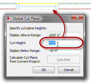
If you can find a global cut plane level that will cut through all of your Windows and not adversely affect the display of other objects, the easiest way to get all of your Windows to display identically is to raise the global cut plane to that level.
If there is no single global cut plane height that will cut through all Windows, or any such height has unwanted side effects on other objects, you can leave the global cut plane height at your standard height and override the cut plane on Walls. This is done on the Cut Plane tab, by checking the Override Display Configuration Cut Plane toggle, and then entering the desired Cut Plane Height, if you are editing the display settings via dialog, as shown below.
If you are editing on the Display tab of the Properties palette, in the Object Display Properties category, in the Cut Plane subcategory, change the Override cut plane property to Yes and then enter the desired value in the Height property.

If even limiting the cut plane adjustment to Walls with Windows above the global cut plane has unwanted side effects, or you would just prefer not to adjust the cut plane at all, you can still make Windows above the cut plane appear like Windows at the cut plane, by turning on the Frame Above Cut Plane, Sash Above Cut Plane and Glass Above Cut Plane components in the Plan Display Representation for Windows and making the display settings for these components match that of the Frame, Sash and Glass components, respectively.
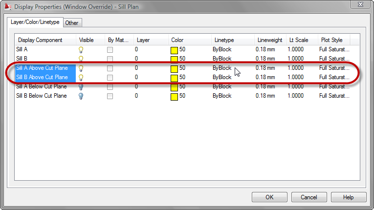
Also turn on the Sill A Above Cut Plane and Sill B Above Cut Plane components and make the display settings match those of the Sill A and Sill B components, respectively.
Finally, edit the display settings of the Plan Display Representation of the Wall, checking the Hide Lines Below Openings Above Cut Plane toggle on the Other tab.

* - You can also make the edits using the Display tab of the Properties palette, but you will have to be able to both select the Window and have the Plan Display Representation active at the same time. To do this, you can either set the Top view direction active with a Display Configuration that uses the Plan Display Representation for the Top view, such as the Medium Detail Display Configuration and temporarily set the Cut Plane high enough to intersect the Window so you can select it, or you can split the Model "tab" into two viewports, setting one to one of the Isometric views in which you can select the Window and setting the other to the Top view direction. Select the Window in the Isometric viewport, then left click in the Top viewport to make it active, and you will have access to the Plan Display Representation and its components on the Display tab of the Properties Palette. You can then select the display level to which the changes are to be applied and then choose/edit each component.

** - The Above Cut Plane component, Display Inner Lines Above toggle and Hide Lines Below Openings Above Cut Plane interact in a similar fashion as the Below Cut Plan component, Display Inner Lines Below toggle and the Hide Lines Below Openings at Cut Plane toggles. See ACA Wall Display Settings at Openings for a detailed description of the interaction.

November 26, 2010

ACA 2011 - Opening Location Changes - Part 4

First Post in Series: ACA 2011 - Opening Location Changes - Part 1
Previous Post in Series: ACA 2011 - Opening Location Changes - Part 3

To wrap up this series on opening location changes in AutoCAD® Architecture 2011, we will look at the ribbon tools that have been provided to make using them somewhat less tedious. Several choices have been combined into one ribbon tool, reducing the number of steps needed when working "manually", as presented in the previous articles.

These tools are located on the Wall contextual ribbon tab, on the General panel, so in order to access them, you will need to select a Wall. The Door and Window tools are now split buttons, and if you click on the lower half of the tool (the part with the arrow icon), you will get a list of tools from which to choose. For Doors, these tools are Door (DOORADD command), Offset from Grid Line (DOORADD GRID YES POSITION OFFSET command), Center between Grid Lines (DOORADD GRID YES POSITION CENTER command), Evenly between Grid Lines (DOORADD GRID YES MULTIPLE command), Evenly between walls (DOORADD GRID NO MULTIPLE command) and Entire Wall (DOORADD WIDTH MAXIMIZE command).The same options are available for Windows (substitute the WINDOWADD command for the DOORADD command).Since Openings and Door/Window Assemblies do not offer the relative to grid line or multiple options, there are no additional choices on the Opening-Door/Window Assembly tool.
One thing to keep in mind is that when you choose one of the Door or Window tools from the flyout other than the "plain" Door (DOORADD) or Window (WINDOWADD) tool, some of the options associated with that tool will become your new default options. The Relative to grid and Position properties will retain the selected option. The Multiple insert property will maintain a default value of No.

I personally do not see much use for the Entire Wall tools, particularly with respect to Doors, but if you need to fill an entire Wall segment with a Door or Window, the option is there. I would be more likely to want to use the Entire Wall option with a Door/Window Assembly, but that is not an option for Door/Window Assemblies.

November 12, 2010

ACA 2011 - Opening Location Changes - Part 3

First Post in Series: ACA 2011 - Opening Location Changes - Part 1
Previous Post in Series: ACA 2011 - Opening Location Changes - Part 2

Another new feature is the ability to place multiple openings at once. As with the relative to grid feature, the multiple openings feature only applies to Doors and Windows. The openings can either be spaced evenly on the selected segment or centered on the segment with a fixed offset between the openings. Relative to grid can be set to either No (use Wall Ends or intersecting Walls) or Yes (use intersection Grid lines) to determine the Wall segment over which the multiple openings will be placed. In the images here, a Window object will be placed with Relative to grid set to Yes.

The sequence of picks and settings is somewhat fussy, so pay close attention to the following. If you prefer, you can also read the Command: line prompts and set the property values there using the command options.
  1. Start WindowAdd command by whatever means you normally do (eg, tool palette tool).
  2. Select a Wall in the drawing.
  3. On the Properties palette, on the Design tab, in the Dimensions category, set the desired Width and Height (or choose the desired Standard size).
  4. In the Location category, set Relative to grid to the desired value. The value of the Position property does not matter.
  5. Set the Multiple insert property to Yes. Notice that the Command line prompt now asks you to select a Wall segment. Yes, you will need to select a Wall again, but this time you need to pick the exact segment you want. As you hover over a Wall, notice the solid red line that shows up, in addition to the Wall highlight (assuming you have highlighting while selecting turned on).The red line defines the extents of the Wall segment over which the multiple openings will be inserted. When you have the segment you want, select the Wall
  6. You can now set the number of openings to insert, either in the Number to insert property or at the Command: line prompt. The initial default value will be the maximum number of openings that can be fit along the selected segment. For the example here, the default was 6, but I changed it to 3.
  7. In the Location category, choose the desired value for the Spacing property, Equally or Offset.
    • If you choose Equally, then the difference between the segment length and the sum of the Widths of the openings, will be divided into equal segments, at the beginning, between each opening and at the end.
    • If you choose Offset, another property, Offset multiples, appears, allowing you to specify the distance between the openings. The entire array is centered on the segment, so the additional space is divided equally to each side.
  8. Finally, left click in the drawing area to accept the arrangement ghosted on the screen and continue on with the command in progress (WindowAdd in the example). The Multiple insert property will reset to no, so if you want to add another set of multiple openings of the same object, you will need to start the sequence above from Step 3 (Step 5 if the opening size and Relative to grid are to remain the same).
The next installment will look at the ribbon tools that can make using these features less fussy.

Next Post in Series: ACA 2011 - Opening Location Changes - Part 4

October 16, 2010

ACA 2011 - Opening Location Changes - Part 2

First Post in Series: ACA 2011 - Opening Location Changes - Part 1

The first post covered the splitting of the Offset/Center option into separate Offset and Center options when placing a opening (Door, Window, Door/Window Assembly or Opening) object in a Wall, and showed how that worked for a Door, using Wall ends or intersecting Walls to define the Wall segments to which the Offset or Center applies. In this post, we will look at the newly added "Relative to grid" property, which only applies to Doors and Windows.

When set to "No", Walls are used to define the segments, as in previous releases. When set to "Yes",AutoCAD® Architecture will use grid lines that intersect the Wall to determine the Wall Segment over which the Center or Offset will be applied. In the image below, the Center option has been selected, and, as you can see, the Window is centered between the two grid lines crossing the Wall, ignoring the intersecting Wall.*
The Offset option works in a similar fashion, using intersecting Grid lines to define the offset points.
As mentioned in the first post, any type of Grid can be used - Ceiling Grids, Column Grids or Layout Grids - provided that the Grid is visible in the currently active Display Representation Set. Ceiling Grids are less likely candidates, given their usually small cell dimensions.

The next post will examine the new multiple option when placing openings.

Next Post in Series: ACA 2011 - Opening Location Changes - Part 3

* - For the purposes of this article, I extended the Column Grid by one additional bay, so that the Column Grid lines perpendicular to the exterior Wall would actually cross the Wall. If I had not done so, ACA would have found no grid lines and would have acted on the entire length of the Wall instead. Adding Grid Labels does not change anything, as what appear to be Grid Line extensions are actually the Anchor objects that attach the grid bubble Multi-View Blocks to the Grid, masquerading as Grid Lines. This is a major drawback for this feature in my opinion, as I can see wanting to have multiple, evenly spaced openings in a structural bay on an exterior Wall to be relatively common, but do not expect to be using this on interior Walls very often, if ever.

October 09, 2010

ACA 2011 - Opening Location Changes - Part 1

One item that has changed in the 2011 release* of AutoCAD® Architecture is the way that openings (Doors, Windows, Door/Window Assemblies and Openings) are placed in Walls. Instead of a choice between Unconstrained and Offset/Center, you now have three choices: Unconstrained, Offset and Center. While you may initially miss having Offset and Center available at the same time, I am told that these needed to be split into separate options, in order to enable the new "Space Evenly" options that allow you to place multiple, evenly spaced, Doors or Windows in one operation. Also new is the choice to have the offset or centering boundaries be Walls (as before) or Grid Lines. Any type of grid (Layout, Column, Ceiling) will work, although Column and Layout will most likely be the ones most often used. I will take a look at these new options in the next few posts.

You will want to have your Properties palette open when placing openings in order to have control over the placement. (You can also make use of Command-line prompts or Dynamic Input, although the latter is failing to display a list of Position options for me.) Look on the Design tab, under the Location category, which is at the bottom of the tab. Notice that the first three properties have an eight-pointed asterisk icon at the left side. That indicates that these properties are only available at the time of object creation.Note that until you select a Wall (the first prompt of the DoorAdd command), the Multiple insert property will be grayed out and inactive. This post will focus on placing a single opening relative to Walls. With Relative to grid set to no, the Position setting will be relative to Walls. As in previous versions, setting Postion to unconstrained allows you to move your cursor to the place where you want the Door and click to place it - or, for more precision, you can type a value into the Dynamic Dimension Input, if enabled. You may also want to turn off any running Object Snaps when placing openings.
Changing the Position property to Offset in the Properties palettewill add a new property, Automatic offset,in which you specify the distance from which the Door is to be offset from the Wall end or intersecting Wall. This should be be familiar, as it worked the same way before, only now you can only place an offset Door, rather than being able to offset or center the Door, depending upon your cursor position. With the Position property set to Offset, the Door can only be placed offset from the Wall End or from an intersecting Wall.

Setting the Position property to Center will remove the Automatic offset property, if it was previously present.With this Postion setting, the Door will be constrained to the middle of the Wall or Wall segment.
So far, the only new thing has been the splitting of Offset and Center into separate options. The next post will look at the new Relative to grid option.

Next Post in Series: ACA 2011 - Opening Location Changes - Part 2

* - Subscribers who installed the 2010 Subscription Advantage Pack have already seen these changes. The ribbon tools associated with them have been integrated into the ACA 2011 ribbon, rather than being on a separate ribbon tab, as was the case with the Subscription Advantage Pack.