March 30, 2011

AutoCAD 2012 New Feature - In-Canvas View Controls

The In-Canvas View Control is a new feature added to AutoCAD® 2012, so it is also available in ACA 2012. When combined with the tools on the Navigation Bar and the ViewCube, you really do not need to tear off the View panel from the Home ribbon tab anymore.

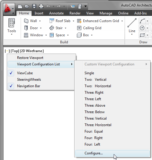
Appearing at the top left corner of the drawing area on the Model "tab" (TILEMODE 1) and consuming a minimum of screen real estate, there are three text strings enclosed in square brackets; a left click on one of the strings gives access to popup menus related to that particular view control. The first string - either a "-" (one viewport displayed) or a "+" (multiple viewports displayed - allows you to control the visibility of the ViewCube, SteeringWheels and Navigation Bar as well as access to Viewport configurations, including any custom configurations you may have created.You can also temporarily maximize the currently active viewport and then restore the previous viewport configuration using this first menu.

The second string allows you to quickly select a Model View to restore, either preset or custom, as well as access to the View Manager. The name of the current View direction or Model Space View (if current) is displayed in the second string, for easy reference while you work.
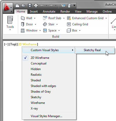
The third string displays the name of the current Visual Style, and the menu allows you to set a different Visual Style current (predefined or custom) or to open the Visual Styles Manager.
The VPCONTROL System Variable controls the display of the In-Canvas View Controls. Set it to Off (0) to hide the controls. Set it to On (1) to display the controls. It is stored in the registry, so the setting will hold for all drawings.

With TILEMODE set to 0, you will not see the View Controls unless you maximize a viewport on a Layout "tab".

March 26, 2011

ACA 2012 Enhanced Feature - Column Grids

Two improvements to the Column Grid feature have been added in the 2012 release.

Automatic Labeling of Custom Column Grids
With the linework you wish to convert to a custom Column Grid drawn, on the Home ribbon tab, on the Build panel, select the arrow icon at the right side of the Enhanced Custom Grid split button and choose the Custom Grid Convert tool.(As always, click on an image to see a full-size version. Use the Back button in your Browser to return here.) Following the Command: line prompts, select the linework to be converted. The next prompt asks you to specify the label extension distance. Accept the default value, enter a new value or type "N" (No labels command option) if you do not want to add labels automatically at this time. Type "Y" to erase the selected linework or "N" to keep it, and press ENTER to end the command.The custom grid will be created, and labels will be added at the ends of the grid lines, if you did not choose the No labels command option. Notice, however, that the labels all have "-" as a default value.Note: If you did choose the No labels option when creating the Column Grid, you can add labels to it by selecting it and, on the Column Grid contextual ribbon tab, on the Label panel, choosing the Add Labels tool.

With the new, default-labeled custom Column Grid selected, on the Column Grid contextual ribbon tab, on the Label panel, choose the Edit Labels tool.You can now pick a single grid line or a series of grid lines that are to be sequentially numbered, starting with the one to receive the lowest value. When you are done selecting, press ENTER and then enter the value for the first (lowest) grid line and press ENTER to change those values.

The prompt will repeat, so you can pick a second grid line or series of grid lines, starting with the lowest value, and label those as well. When you are done labeling grid lines, press ENTER to end the AecCustomColumnGridLabelEdit command.
The value you enter for the label can be alphabetic or numeric; either will be incremented when you select a series of grid lines. You can also enter something like "1.1" and choose a series of grid lines and get "1.1", "1.2", 1.3", etc. You can use the Edit Labels tool at any time in the future to edit the values of a single grid line or a series of grid lines.

Labels are automatically added to both ends of each grid line. You can ERASE any labels you do not want to keep.

Enhanced Custom Grids
You can now use an existing regular Column Grid or Enhanced Custom Grid as the starting point for a new Enhanced Custom Grid. On the Home ribbon tab, on the Build panel, choose the Enhanced Custom Grid tool.In the Column Grid dialog, click on the Set From button,and then choose the desired Column Grid. The parameters of the selected grid will populate the Column Grid dialog as a starting point for your new Enhanced Custom Grid. A non-enhanced custom Column Grid (created from linework) can not be selected as the "Set From" object.

March 22, 2011

ACA 2012 New Feature - Corner Windows


One of the new features added to AutoCAD® Architecture 2012 is one for creating corner windows. An easy way to do so has been on the wishlist for some time, and now it is here. Corner Windows make use of "regular" ACA Window Styles, which now feature some added properties on the Dimensions tab in the Frame area.As you can see in the image above, you have the option of specifying butt glazing at the corner. If this toggle is unchecked, you will get a frame at the corner, and you can specify the exposed inside width of the frame (dimension "K"). Window Styles from previous releases will default to having the Butt Glazing at Corner toggle checked (K - Width of 0). The out-of-the-box "regular" Window Styles also have the Butt Glazing at Corner toggle checked. While there is no reason to create a separate Window Style with "Corner Butt Glazing" in the name, the out-of-the-box content includes a "Corner Butt Glazing - Picture" Window Style that is used by the Tool palette tool of the same name.
Corner Windows are placed using a new command, WINDOWCORNERADD. You can create your own Corner Window Tool palette tool by copying one of the out-of-the-box tools and modifying the properties to use your desired style. In addition to the out-of-the-box style-specific tools on the Corner Windows palette in the Design Tool Catalog (under Doors and Windows), you can find a generic Corner Window tool in the Stock Tool Catalog, under Architectural Object Tools. You can also invoke the WINDOWCORNERADD command on the Home ribbon tab, on the Build panel, by clicking the down arrow icon at the right side of the Window split button and choosing the Corner Window tool.
Corner Windows must be placed by selecting a Wall; they can not be inserted as free-standing objects, like "regular" Windows. The Wall selected must also be intersected by another Wall, and both must clean up to form an "L" corner; the angle need not be 90 degrees. "T" or "X" intersections will not work. Curved Walls are also not currently supported. If you try to place a Corner Window and nothing happens when you select a Wall, check the Command: line for helpful messages such as "No valid wall intersection found for selected wall." to help you figure out why the Corner Window is not being placed.
After selecting the first Wall, a preview of the Corner Window will appear on screen. If there are valid corners at each end, you can move your cursor closer to the desired end to have the preview appear at the correct end. When adding a Corner Window, you will find that instead of being able to edit the usual Width property (Dimension A, which is still there, but not editable), you now have two new properties, Width 1 (Dimension E) and Width 2 (Dimension F), which allow you to control the width of each leg of the Corner Window. Width 1 applies to the leg within the selected Wall, Width 2 applies to the other Wall. The Width property will display the sum of the Width 1 and Width2 values.In the image above, the horizontal Wall was selected, and the dynamic dimension for Width 1 is initially active. You can set the widths using the dynamic dimensions or by editing the properties on the Design tab of the Properties palette. Use the Opening measure property to choose whether the specified Width 1 and Width 2 values are measured to the Outside of opening, Center of opening or Inside of opening.
Standard Sizes remain the same as before - when placing a Corner Window, the width dimension specified is used for both legs.

Corner Windows can be tagged and scheduled just like "regular" Windows". The Width automatic property source will show both widths, separated by " x ".
Corner Windows can be grip edited similar to "regular" Windows, with some Corner-Window-specific changes. The arrow-shaped Flip grip located at the jamb will swap the Width 1 and Width 2 legs. This does not just swap the width values, but actually moves the Width 1 leg to the other Wall, as if it had been selected first. The square Location grip offers a different first option. Instead of "Move along" Wall, which makes no sense for a Corner Window, it offers "Specify wall corner", which allows you to move the Corner Window to any other valid "L" corner Wall intersection, even one involving two different Walls.
Cautions

Corner Windows should not be used in projects where any other team members are not on the 2012 release. While ACA 2012 uses the AutoCAD® 2010 file format and ACA 2010 and 2011 will be able to open the file, neither of those releases will support the proper display of Corner Windows and you will get a "regular" Window, with the width equal to the sum of the center of opening values of Width 1 and Width 2, anchored to the Width 1 Wall at the time it was saved in 2012 and hanging over the end of the Wall, as seen in the image below.Schedules created in 2012 with Corner Windows will also show undesired results when opened in 2010 or 2011. (The Width column will show like a formula property with an error, displaying the entire formula used to calculate the Width value.) In limited testing, it appears that opening/editing/saving in 2011 and reopening in 2012 causes no harm, but you will want to test that in your own environment and with the sorts of edting you expect to do before relying on it being safe.

The openings created by Corner Windows are not taken into consideration when using the Offset or Center options when placing other opening objects (Doors, Windows, Openings, Door/Window Assemblies) in a Wall that has a Corner Window. This is not the behavior I expected, so you will want to keep that in mind.

Any type of Window Style can be used as a Corner Window, but it may not be appropriate for all types. For example, you can set up a butt-glazed Glider Peak Corner Window, but that does not mean you should (nor does it mean it could be built).

February 19, 2011

Adding Show Desktop Tool to Quick Launch Toolbar (Windows XP Professional x64 Edition)

I just got a new 64-bit computer at work, and the first thing I "missed" was the "Show Desktop" tool in the Quick Launch toolbar. My computer desktop tends to accumulate quite a few Windows as the day goes on, and I make frequent use of that tool. While there are alternative methods for invoking the command ("Microsoft key"+D or right clicking on the Taskbar and choosing "Show the Desktop" from the context menu, I kept finding myself trying to click on the familiar tool that was no longer there.

At home, I added it back in by copying the file from my 32-bit laptop. I found this knowlege-base article on the Microsoft site, which explains how to create a file to run the "Show the Desktop" command from a Quick Launch toolbar tool.

There is a "Fix it for me" button, but I chose to do it manually, which is really quite easy. Start a Notepad file and paste the given text into it.
[Shell]
Command=2
IconFile=explorer.exe,3
[Taskbar]
Command=ToggleDesktop
Save the file to your Desktop (or some other location, if you prefer), using the name Show desktop.scf and then drag that file onto the Quick Launch toolbar. The old, familiar icon is back and ready for action.

Note: The above works when running Windows XP Professional x64 Edition, assuming that you have the Quick Launch toolbar displayed on the Taskbar. It should work on Vista as well. Apparently, Windows 7 has a button on the far right side of the Taskbar that performs this function, but you can not move its position; in order to use the above, you would have to add the Quick Launch toolbar to the Taskbar, as it is not available by default.

February 05, 2011

Complete Uninstallation of Autodesk Products

If you ever find yourself needed to uninstall an Autodesk product and want to be certain that you have completely removed the product so that you can have a clean reinstallaion, you can find instructions for doing just that in this Knowledge Base article.

January 19, 2011

ACA Section Tail Scaling

Here is a heads up to anyone who may be placing Section Marks with "tails" in Model Space from a Layout through a Viewport. The AecCallout command has an apparent defect in the way it creates the anonymous block for the tail. It works fine when placing the Section Mark from the "Model tab" (when "Model" or TILEMODE 1, rather than a "Layout" or TILEMODE 0 is current). It also works correctly when in a Layout and working through a Viewport when the scale of the Viewport is the same as the scale set for "Model".

But if the Viewport's scale is not the same as the "Model" scale, then the anonymous block that gets created is improperly sized. The correct annotation scale (matching that of the Viewport) is applied to the tail block, but the improper size of the block definition results in the final block displaying the same size as one placed through a Viewport that has the same scale as "Model".

To avoid this problem, you can do one of the following:
  • Place all callouts from the "Model tab" (TILEMODE 1), setting the desired drawing scale prior to placement.
  • Remember to switch to "Model"/TILEMODE 1 and set the drawing scale to match that of the Viewport and then switch back to the Layout.
  • Place the callout in the Viewport and then, after placement, change X-scale factor of the block to get it to be the right size [Viewport scale factor/Model scale factor]. The anonymous block created has uniform scaling, so the change to the X-scale factor will be applied to the Y- and Z-scale factors as well.
I imagine that I would generally be placing the callout in TILEMODE 1, but if not, I would most likely change the scale factor of the anonymous block, rather than hopping back and forth from "Model" to "Layout". As noted in this thread in the AutoCAD® Architecture Discussion Group, this problem has been observed in the 2009, 2010 and 2011 releases.

The block at the other end of the Section Mark, displaying the Section Number and, possibly, the Sheet Number, does not suffer from this defect.

January 10, 2011

Old AUGI Forums Restored

The pre-December 2010 AUGI Forums are back on line and ready to receive new posts, at http://forums.augi.com/. This is being described as a "beta", as there are still additional changes to be make to incorporate previous customizations into the more recent version of vBulletin that is now being used (where such customizations are deemed worthy of keeping, of course).

At this time, if you log into the main AUGI site and choose the Forums link, you will need to click on the http://forums.augi.com/ link to get to the new forums. The old ExpressionEngine forums are now read only, but can be viewed (separately) for reference. At some point in the future, those posts are to be merged into the vBulletin forums.

The archived AUGI Training Program (ATP) classes are also available again. You can navigate to the archived course material download pages from the Education link on the main AUGI site.

If you experience problems logging in to the site or accessing the old forums, try logging out of the site and deleting your AUGI cookies. When you then log in again, new cookies should be generated that will get you in to both sites.

January 05, 2011

Revisions and Dependent Views in Revit

I came across an issue related to my previous post on Revision Clouds and Dependent Views in Revit® Architecture. The floors on my project are shown in three sectors on three separate sheets at 1/4" = 1'-0", and I had a relatively small change to make within a single room in the middle or "B" sector that happened to be right next to the match line separating it from Sector "C" on my project. Due to the floor geometry, the match line is neither straight nor parallel to the dependent view cropping boundary, and at the revised area, a good deal of the room in which the change was made appears on the Sector "C" sheet as well.

I had made the change, clouded it and reissued the Sector "B" sheet without giving any thought to the Sector "C" sheet. Some time later, I opened the Sector "C" sheet and was checking to see if the revisions on it agreed with the plot in my half-size set and was surprised to find that an additional revision was listed. I quickly determined that the revision was for the change that I had documented in Sector "B" and that the reason it showed up was because the revision cloud, as I had drawn it, ended up being entirely within the annotation crop boundary for the dependent view shown on the Sector "C" sheet. That annotation crop boundary was a substantial distance beyond the model crop boundary, at what I believe was the initial default location.

Since the revision was generated by the revision cloud, there was no way to manually remove it from the list of revisions on the Sector "C" sheet. In order to remove the revision from the Sector "C" sheet, I edited the annotation crop boundary, dragging it as tight to the model crop boundary as possible, and then modified the revision cloud so that part of it extended beyond the annotation crop boundary. As noted in the previous post, once the revision cloud was not entirely within the Sector "C" annotation crop boundary, it no longer showed up in the Sector "C" dependent view and the revision no longer showed on the Sector "C" sheet, and I was good to go.

Modifying the annotation crop boundary caused a few annotation objects that had previously showed on the Sector "C" sheet to disappear, but these were all beyond the match line and still show on the Sector "B" sheet. I will need to remember to edit the annotation crop boundaries that are beyond a match line from the default location on future projects, and to keep in mind where those annotation crop boundaries are when placing future revision clouds in the vicinity of match lines.

December 17, 2010

Old AUGI Forums to be Restored

As announced by incoming president David Harrington in this thread, the contents of the AUGI forums that were available prior to the change to the new website format are expected to be restored and that the forums section of the website will be using the "old" vBulletin software. This is welcome news on both counts, and will, I hope, result in the restoration of links to threads and ATP class materials made in other posts in this blog, which, as noted here, are currently not valid.

December 11, 2010

Displaying Windows Above the Cut Plane in ACA

Over the years, there have been a number of requests in the Autodesk Discussion Groups and the AUGI Forums on how to get a Window that is above the global cut plane to display in a plan view (Top view direction). There are a number of approaches to this, and which one you should use depends upon how you want to see the Window and whether any particular change has unwanted side effects. For the purposes of this investigation, I am going to assume that the Window in question really is meant to be above the global cut plane and is not simply misplaced vertically in the Wall. I am also assuming that you need to model the Window accurately, that is, draw it to the intended size and place it in the correct vertical position, so that it schedules and/or shows up in generated section/elevations correctly. I will be using imperial units, using the out-of-the-box global cut plane of 3'- 6", but the same display techniques will work in metric units as well.(As always, click on any image to see the image full size. Use the Back button on your browser to return to the article.)

First, you need to decide how a Window above the cut plane should display. If it is a clerestory Window that is well above the cut plane, you may want to indicate the Window in a plan view, but use different graphics than you would for one that is actually cut by the cut plane, so that it is apparent in the plan view that the Window is above the cut plane. On the other hand, you may want one that is not very far above the cut plane to appear just like others that do intersect the cut plane.

Different Graphics
The out-of-the-box Plan Display Representation for Windows includes "Above Cut Plane" components for the Frame, Sash and Glass, but they are turned off. You can have above-cut-plane Windows display when the Plan Display Representation is active by turning on these components and setting the color, linetype and lineweight to suit your needs. This can be done at the Drawing Default, Style or Object level. Drawing Default settings are best edited in the Display Manager. Style-level settings are most easily edited through the Style Manager, or by selecting the object and editing its style. Object-level settings require selecting the object. Because we are making changes to several components, I will be showing the edits using dialogs.* I will also be applying the display settings as Object-level overrides, to allow me to keep a number of different conditions in the same drawing file; you will need to decide whether you should make the changes at the Drawing-Default level (affecting all Windows without a Style- or Object-level override), Style-level (affecting all instances of that Style that do not have an Object-level override) or at the Object-level (affecting just that instance).As shown above, I set an object-level override on the Plan Display Representation of the Window, and turned on the display of the above cut plane components for the frame, sash and glass. I also changed the color, lineweight and plot style to ByBlock and the linetype to HIDDEN2.

If you prefer not to have the Wall Component graphics run through the above-cut-plane Window graphics, you can edit the Plan Display Representation of the Wall, by checking the "Hide Lines Below Openings Above Cut Plane" toggle on the Other tab.
If you would like to have lines at the opening just at the face of the outer component of the Wall, you can turn on the Above Cut Plane component of the Wall. Make certain that the Display Inner Lines Above toggle is unchecked.**
Identical Graphics
If you can find a global cut plane level that will cut through all of your Windows and not adversely affect the display of other objects, the easiest way to get all of your Windows to display identically is to raise the global cut plane to that level.
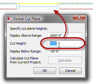
If there is no single global cut plane height that will cut through all Windows, or any such height has unwanted side effects on other objects, you can leave the global cut plane height at your standard height and override the cut plane on Walls. This is done on the Cut Plane tab, by checking the Override Display Configuration Cut Plane toggle, and then entering the desired Cut Plane Height, if you are editing the display settings via dialog, as shown below.
If you are editing on the Display tab of the Properties palette, in the Object Display Properties category, in the Cut Plane subcategory, change the Override cut plane property to Yes and then enter the desired value in the Height property.

If even limiting the cut plane adjustment to Walls with Windows above the global cut plane has unwanted side effects, or you would just prefer not to adjust the cut plane at all, you can still make Windows above the cut plane appear like Windows at the cut plane, by turning on the Frame Above Cut Plane, Sash Above Cut Plane and Glass Above Cut Plane components in the Plan Display Representation for Windows and making the display settings for these components match that of the Frame, Sash and Glass components, respectively.
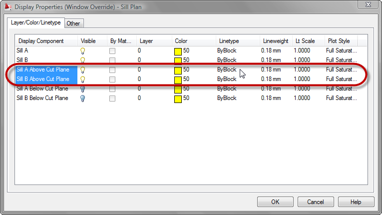
Also turn on the Sill A Above Cut Plane and Sill B Above Cut Plane components and make the display settings match those of the Sill A and Sill B components, respectively.
Finally, edit the display settings of the Plan Display Representation of the Wall, checking the Hide Lines Below Openings Above Cut Plane toggle on the Other tab.

* - You can also make the edits using the Display tab of the Properties palette, but you will have to be able to both select the Window and have the Plan Display Representation active at the same time. To do this, you can either set the Top view direction active with a Display Configuration that uses the Plan Display Representation for the Top view, such as the Medium Detail Display Configuration and temporarily set the Cut Plane high enough to intersect the Window so you can select it, or you can split the Model "tab" into two viewports, setting one to one of the Isometric views in which you can select the Window and setting the other to the Top view direction. Select the Window in the Isometric viewport, then left click in the Top viewport to make it active, and you will have access to the Plan Display Representation and its components on the Display tab of the Properties Palette. You can then select the display level to which the changes are to be applied and then choose/edit each component.

** - The Above Cut Plane component, Display Inner Lines Above toggle and Hide Lines Below Openings Above Cut Plane interact in a similar fashion as the Below Cut Plan component, Display Inner Lines Below toggle and the Hide Lines Below Openings at Cut Plane toggles. See ACA Wall Display Settings at Openings for a detailed description of the interaction.