Those still using Autodesk® Revit® products from the 2012 and 2013 releases but who have installed a 2014 or later release product from Autodesk or have in some other way had .NET 4.5 installed on their computer will find that this creates issues with the contextual ribbons in Revit. Due to the recent overhaul of the Autodesk website and the introduction of the Autodesk Knowledge Network, old links to the required updates (2012 & 2013) and hotfix (2012 only) may no longer work. To save others from the effort to search for the reuqired files, here are the current URL's:
2012 - Make sure you have Update Release 2 for your product installed before applying the hotfix.
Revit Architecture 2012 Update Release 2
Revit MEP Update Release 2
Revit Structure Update Release 2
Hotfix - Autodesk Revit 2012 - Ribbon behaviour due to .Net 4.5 installation
2013 - Install the correct version of Update Release 3 for your product. Note that the "one box" version that ships with the Building Design Suites has a different update file than the Revit Architecture, Revit MEP or Revit Structure versions.
Revit Architecture 2013 Update Release 3
Revit MEP 2013 Update Release 3
Revit Structure 2013 Update Release 3
Revit "One Box" (Building Design Suite) 2013 Update Release 3
Showing posts with label 2012. Show all posts
Showing posts with label 2012. Show all posts
April 02, 2014


December 03, 2013
Revit: Hosting Face-Based Light Fixtures to Ceilings in Linked Files
We ran into an issue at the office today, and I wanted to document the solution for my own future reference. Our firm has architects and engineers in-house, and each discipline typically works in separate models that are then linked into each other. This particular project was being done in the 2012 versions of Revit MEP, Revit Structure and Revit Architecture. The electrical engineers found that they were not able to place face-based light fixture families in their model, and host them to the ceilings that were modeled in the linked architectural model. Reflected ceiling plan views were being used and the ceilings were visible, but the fixtures would only host to the Walls.
It turned out that the Ceiling model category was turned off in the affected views in the Electrical model. This did not prevent the linked architectural model from displaying the ceilings, and they were also TAB-selectable in the Electrical model. But it did prevent Revit MEP from "seeing" them as a potential host. Once the ceiling category in the electrical model was turned back on in those views, Revit was able to find the ceilings and host fixtures to them. It was necessary to check the Show categories from all disciplines toggle in order to do this.
It turned out that the Ceiling model category was turned off in the affected views in the Electrical model. This did not prevent the linked architectural model from displaying the ceilings, and they were also TAB-selectable in the Electrical model. But it did prevent Revit MEP from "seeing" them as a potential host. Once the ceiling category in the electrical model was turned back on in those views, Revit was able to find the ceilings and host fixtures to them. It was necessary to check the Show categories from all disciplines toggle in order to do this.
October 08, 2011
ACA 2012 Service Pack 1 Released
Apparently Autodesk has decided to go back to calling them Service Packs, rather than Updates. Service Pack 1 for AutoCAD Architecture 2012 is now available - download it from here.
Be certain to read the README for installation instructions. According to the README, Service Pack 1 restores the former ARRAY command functionality, in a new command called ARRAYCLASSIC. There is also a new System Variable, SNAPGRIDLEGACY: set this to 1 to have the cursor always snap to the grid (legacy snap behavior); set it to 0 to have it snap to the grid only when AutoCAD has prompted for point input.
The following ACA defects have been addressed:
Drawing Manager
The following AutoCAD defects have been addressed:
3D Navigation Tools
Be certain to read the README for installation instructions. According to the README, Service Pack 1 restores the former ARRAY command functionality, in a new command called ARRAYCLASSIC. There is also a new System Variable, SNAPGRIDLEGACY: set this to 1 to have the cursor always snap to the grid (legacy snap behavior); set it to 0 to have it snap to the grid only when AutoCAD has prompted for point input.
The following ACA defects have been addressed:
Drawing Manager
- Selecting a sheet with a long name may cause unexpected behavior in AutoCAD Architecture.
- Opening a project with a large number of files in a 64-bit machine may cause AutoCAD Architecture to crash.
- Space containment does not work on a 64-bit operating system.
- Exporting multi-view blocks to AutoCAD may result in an incorrect size.
- Some AEC ARX files are loaded when running AutoCAD Architecture with an AutoCAD profile.
- Renovation function fails when you add a door or window object during renovation mode.
- Sometimes the renovation toggle remains enabled even after exiting the renovation mode.
- Building geometry may change after you activate and then disable the live section.
- Roof or roof cap solid hatch might be displayed in section incompletely.
- Some merged space area are calculated incorrectly.
- When the unit area is inconsistent with its unit length, the calculated space area might be inaccurate.
- Adjusting column grid can cause beams to lose connection with the columns.
- Adding tags for doors on multiple reference copies may cause unexpected behavior in AutoCAD Architecture.
- REPOSITIONALONG command does not work for doors and windows.
- Running the JOIN command on two connected walls may cause unexpected behavior in AutoCAD Architecture.
- When you offset a wall using another wall with the same direction as the reference, the offset wall may be created in the opposite direction.
- The Below Cut Plan display component of doors or window may not display.
The following AutoCAD defects have been addressed:
3D Navigation Tools
- 3DConnexion settings are not being remembered after changes are made.
- 3Dconnexion device will not cancel the current command.
- With dynamic input off dragging the height handle of an extruded line will not always stretch by the value and direction of the drag.
- AutoCAD may become unstable when rebuilding a helix to a spline where the selection was not dropped.
- AutoCAD may become unstable while attempting to load a DCL file with errors from a long file name.
- Tooltip does not appear when Additional tool tip string is set in “AcEdInputPointMonitor::monitorInput”.
- API fix: This fix will respect the custom color, line pattern and line weight when selecting the entities including external reference.
- Autoloader fails when SeriesMax parameter set to linked.
- Autoloader loads partial CUI but may not display it when the bundle is removed and reinstalled.
- When platform="AutoCAD*", bundles will be load on ACAD and Vertical.
- Using Autoloader to add custom CUI files that contain WPF Custom Controls will not work as it needs a registry entry.
- AutoCAD may become unstable while snapping to blocks containing OLE objects.
- Editing attribute text in EATTEDIT dialog sometimes results in a fatal error.
- When a drawing is saved from within the Block Editor, the entire content of the drawing is sometimes lost and replaced with the content of the block being edited.
- Sometimes there is a delay while trying to modify blocks containing a Block Table Parameter.
- AutoCAD becomes unstable when entering the block editor, attempting to edit a dynamic block which has geometry on a locked layer.
- Sometimes the BEDIT toolbar does not get hidden after exiting block editor.
- You may receive an error at the command line after enabling a WinTab driver and the tablet will not function.
- Integrated chipsets are unable to return available video memory correctly.
- Arcs and circles viewed on edge appear as a single line. This changes 2D DWF/DWFx drivers to plot them as a single line, rather than a polyline.
- AutoCAD may become unstable when using the "UNDO" command on drawings that are 2 gigabyte or larger.
- Ordinate dimensions in paper space are not correctly reflecting the distance from paper space UCS.
- AutoCAD may become unstable while closing a drawing after etransmitting it using the COM API.
- Autodesk Exchange may display a non-subscription link after updating to a subscription serial number.
- User login IDs that contained special characters like “@” could not log in to online services.
- AutoCAD may become unstable when using the NCOPY command.
- Overkill may delete polylines incorrectly when working with reversed polylines.
- Overkill may not work well when there is an arc segment in between 2 line segments.
- AutoCAD may become unstable when using the “separate hatch” option.
- Multi frame QuickBird Tiff image files may not display expected colors.
- When trying to insert an Adobe Photoshop PSD file it was not visible in the file filter list.
- AutoCAD may become unstable when inserting an AdobePhotoshop PSD file.
- Changing layer colors of layers beginning with non-alphanumeric characters may result in other layers changing colors.
- The layer state Ribbon control does not honor the apply properties viewport overrides.
- AutoCAD may become unstable when drawings with multileaders are saved to older versions.
- AutoCAD may become unstable when editing polylines.
- NCOPY may fail to copy objects contained in blocks that were inserted into paper space.
- Mtext Paragraph spacing value cannot be edited once a value is set.
- True Type (TTF) font text or mtext is blurry, bold, and distorted when the viewport is non-orthogonal because XY values are not exactly zero.
- AutoCAD may become unstable when copying from an Excel file back to AutoCAD.
- Cannot open drawing files from file Explorer if the drawing contains a "'%'" in the file name.
- AutoCAD may stop responding when saving and or opening drawings with Symantec Norton 360 Version 5 installed on your system.
- You will be unable to open drawings created using a non-Autodesk product when using the Open() API.
- AutoCAD may become unstable when selecting the grid in some drawings.
- AutoCAD may become unstable after editing MTEXT in a viewport and when exiting the program.
- Area is wrong when coincident constraints are applied to entities.
- AutoCAD may become unstable when using PDF Export on files that contain MS Mincho font.
- AutoCAD may become unstable when unloading a PDF underlay.
- AutoCAD may become unstable when an undefined PDF underlay is unloaded.
- AutoCAD may become unstable when plotting drawings that include “MS Mincho” to PDF.
- Drawings containing many layers may become slower with each pan and zoom operation when the ribbon is active. Performance improvement in 64bit COM APIs.
- You may experience data loss when sending multiple plots to Xerox printers.
- AutoCAD may become unstable when selecting plot preview.
- AutoCAD may become unstable when using the purge command.
- The linetype preview may be missing from the linetype dropdown in Ribbon Properties panel when opening drawings from the Application Menu.
- Ribbon Combo Box text eight may be empty when using "TEXTEDIT" on multiple dimensions.
- With Snap enabled, the cursor does not move to snap intervals.
- Turning SNAPGRIDLEGACY ON will restore the old Snap behavior of the cursor when no command is active.
- Restores legacy SNAP behavior during certain LISP-based selection commands.
- Sheet List Table Context menu in Sheet Set Manager (SSM) is missing some menu items.
- Cell style is grayed out when picking inside any cell.
- The data link menu is grayed out after inserting a data link in a table.
- AutoCAD may become unstable attempting to edit a polyline vertices Pedit tangent.
- AutoCAD may become unstable in group selection where the group contains a box.
- When objects are on locked layers you are able to nudge them.
- AutoCAD may become unstable when interacting with the ViewCube while grip editing.
- When right click menus are disabled, selection or crossing right click actions are incorrect.
- AcFocusCtrl cannot be inserted in a VBA form.
- Attribute dialog will be displayed when inserting a block with attributes based on the setvar ATTDIA value.
- AutoCAD may become unstable when using osnap in a 2d hide view.
- AutoCAD may become unstable when interacting between the open dialog and the XREF manager.
- AutoCAD may become unstable when zooming over the XY indicator in Layout.
April 25, 2011
Controlling Did You Know Balloon Notifications
If you never made much use of the Communication Center, you may not miss its absense on the InfoCenter toolbar in the upper right corner. (I am assuming that the shipping version and the release candidate beta have the same interface elements and that this was not added back in at the last minute.)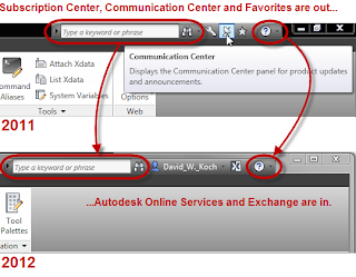
Once you have to manually close a Did You Know message more than one time, you may recall that you were able to have the Did You Know messages close after a period of time that you specified, using the InfoCenter Settings dialog that you accessed from the Communication Center.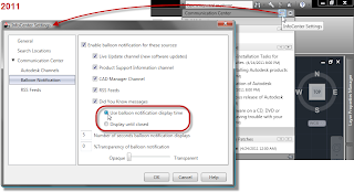 Now how are you going to make those settings?
Fortunately, you still can do so, but you need to know how to access the InfoCenter Settings dialog. Open the Options dialog (one way - from the Application Menu - the big red "A" in the upper left corner - choose the Options button at the lower right corner) and on the System tab, in the InfoCenter area in the lower right corner, click the Balloon Notifications button. This will open the InfoCenter Settings dialog and let you change Did You Know messages from Display until closed to Use balloon notification display time. You can set the number of seconds that balloon notifications display and also choose how transparent the balloons are.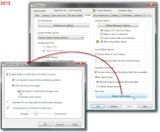 If you do not want to see the Did You Know messages at all, you can also just clear the checkmark in the toggle in front of Did You Know messages (or all balloon notifications).

Once you have to manually close a Did You Know message more than one time, you may recall that you were able to have the Did You Know messages close after a period of time that you specified, using the InfoCenter Settings dialog that you accessed from the Communication Center.
 Now how are you going to make those settings?
Fortunately, you still can do so, but you need to know how to access the InfoCenter Settings dialog. Open the Options dialog (one way - from the Application Menu - the big red "A" in the upper left corner - choose the Options button at the lower right corner) and on the System tab, in the InfoCenter area in the lower right corner, click the Balloon Notifications button. This will open the InfoCenter Settings dialog and let you change Did You Know messages from Display until closed to Use balloon notification display time. You can set the number of seconds that balloon notifications display and also choose how transparent the balloons are.
 If you do not want to see the Did You Know messages at all, you can also just clear the checkmark in the toggle in front of Did You Know messages (or all balloon notifications).
April 03, 2011
AutoCAD 2012 New Feature - AutoComplete
Another new AutoCAD® 2012 feature that I found useful is AutoComplete, which assists you when typing a command or system variable at the Command: prompt. This will be especially useful to ACA users, who, if you are like me, find typing some of the rather long ACA command names tedious at best and difficult to remember at worst. I know many have set up command aliases for many commonly used command in their ACAD.pgp file, but I find myself typing in most ACA commands sufficiently infrequently that it never seemed worth taking the bother to set up and remember command aliases but often enough to now find AutoComplete useful.
AutoComplete offers several options, which can be configured to your liking by either typing AUTOCOMPLETE at the Command: prompt or by right-clicking in the Command: line window and choosing the AutoComplete flyout on the context menu.
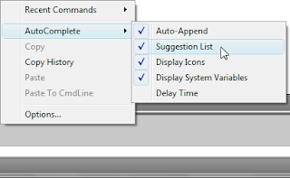 In the headers below, the command line option is given first, followed by the context menu flyout menu choice.
Append/Auto-Append
With the Append option enabled, command and system variable names will be automatically completed, right on the Command: line, as you type. If there are multiple commands that fit what you have typed so far, the first one alphabetically will be completed. The command line option is a Yes/No question; choosing the item on the context menu will toggle the check mark on (= "Yes") or off (= "No").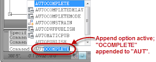
List/Suggestion List
This option determines whether a popup list of commands that start with the characters typed so far will appear. You can then choose the command you want from the list, or continue to type additional characters to reduce the number of commands on the list (or until the command you want is appended, if you have that option turned on). The command line option is a Yes/No question; choosing the item on the context menu will toggle the check mark on (= "Yes") or off (= "No").
Icon/Display Icons
Use this option to determine whether the icon associated with a command is displayed in front of it on the popup list. The command line option is a Yes/No question; choosing the item on the context menu will toggle the check mark on (= "Yes") or off (= "No").
System variables/Display System Variables
Enable this option to include System Variables in the Append and List options; disable it to exclude them. The command line option is a Yes/No question; choosing the item on the context menu will toggle the check mark on (= "Yes") or off (= "No").
Delay/Delay Time
The delay time, entered in seconds, determines how long AutoCAD waits before allowing the Append and List features to be applied, when enabled.
ON
Choosing the ON option will allow the AutoComplete features that have been enabled to be active. Note that if both Append and List are set to "No" (unchecked in the context menu), then using the ON option has no actual effect. But if you previously used the OFF option (see below) to disable the AutoComplete feature when the Append, List or both were set to "Yes", then the "ON" command option will enable AutoComplete with the features that were previously set to "Yes".
OFF
The OFF option disables the AutoComplete function without changing the status of any of the command options. You can later use the ON option to enable the AutoComplete function with the same settings you had prior to using the OFF option.
The ON and OFF options are not available in the right-click context menu. You can turn both the Append and List options off in the context menu to effectively disable the AutoComplete feature, but if you later want both options on, you would have to turn both back on individually.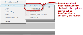 To disable the feature while preserving your settings, use the OFF option of the AutoComplete command at the Command: line.
If you hover over one of the commands in the popup list and ToolTips are enabled and the command has a ToolTip, the ToolTip will display.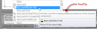
If you load custom LISP routines that define commands, these will also be available in the AutoComplete feature. In the image below, the SELALL command is a custom command I have defined, and after typing "SEL" at the Command: line, the popup list shows the SELALL command and the balance of the SELALL command has been appended, since it is first alphabetically on the list. The SELBLK command is also a LISP-defined custom command.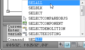
AutoComplete offers several options, which can be configured to your liking by either typing AUTOCOMPLETE at the Command: prompt
 or by right-clicking in the Command: line window and choosing the AutoComplete flyout on the context menu.
 In the headers below, the command line option is given first, followed by the context menu flyout menu choice.
Append/Auto-Append
With the Append option enabled, command and system variable names will be automatically completed, right on the Command: line, as you type. If there are multiple commands that fit what you have typed so far, the first one alphabetically will be completed. The command line option is a Yes/No question; choosing the item on the context menu will toggle the check mark on (= "Yes") or off (= "No").

List/Suggestion List
This option determines whether a popup list of commands that start with the characters typed so far will appear. You can then choose the command you want from the list, or continue to type additional characters to reduce the number of commands on the list (or until the command you want is appended, if you have that option turned on). The command line option is a Yes/No question; choosing the item on the context menu will toggle the check mark on (= "Yes") or off (= "No").

Icon/Display Icons
Use this option to determine whether the icon associated with a command is displayed in front of it on the popup list. The command line option is a Yes/No question; choosing the item on the context menu will toggle the check mark on (= "Yes") or off (= "No").
System variables/Display System Variables
Enable this option to include System Variables in the Append and List options; disable it to exclude them. The command line option is a Yes/No question; choosing the item on the context menu will toggle the check mark on (= "Yes") or off (= "No").
Delay/Delay Time
The delay time, entered in seconds, determines how long AutoCAD waits before allowing the Append and List features to be applied, when enabled.
ON
Choosing the ON option will allow the AutoComplete features that have been enabled to be active. Note that if both Append and List are set to "No" (unchecked in the context menu), then using the ON option has no actual effect. But if you previously used the OFF option (see below) to disable the AutoComplete feature when the Append, List or both were set to "Yes", then the "ON" command option will enable AutoComplete with the features that were previously set to "Yes".
OFF
The OFF option disables the AutoComplete function without changing the status of any of the command options. You can later use the ON option to enable the AutoComplete function with the same settings you had prior to using the OFF option.
The ON and OFF options are not available in the right-click context menu. You can turn both the Append and List options off in the context menu to effectively disable the AutoComplete feature, but if you later want both options on, you would have to turn both back on individually.
 To disable the feature while preserving your settings, use the OFF option of the AutoComplete command at the Command: line.
If you hover over one of the commands in the popup list and ToolTips are enabled and the command has a ToolTip, the ToolTip will display.

If you load custom LISP routines that define commands, these will also be available in the AutoComplete feature. In the image below, the SELALL command is a custom command I have defined, and after typing "SEL" at the Command: line, the popup list shows the SELALL command and the balance of the SELALL command has been appended, since it is first alphabetically on the list. The SELBLK command is also a LISP-defined custom command.

March 30, 2011
AutoCAD 2012 New Feature - In-Canvas View Controls
The In-Canvas View Control is a new feature added to AutoCAD® 2012, so it is also available in ACA 2012. When combined with the tools on the Navigation Bar and the ViewCube, you really do not need to tear off the View panel from the Home ribbon tab anymore.
Appearing at the top left corner of the drawing area on the Model "tab" (TILEMODE 1) and consuming a minimum of screen real estate, there are three text strings enclosed in square brackets; a left click on one of the strings gives access to popup menus related to that particular view control. The first string - either a "-" (one viewport displayed) or a "+" (multiple viewports displayed - allows you to control the visibility of the ViewCube, SteeringWheels and Navigation Bar as well as access to Viewport configurations, including any custom configurations you may have created. You can also temporarily maximize the currently active viewport and then restore the previous viewport configuration using this first menu.
The second string allows you to quickly select a Model View to restore, either preset or custom, as well as access to the View Manager. The name of the current View direction or Model Space View (if current) is displayed in the second string, for easy reference while you work.
The third string displays the name of the current Visual Style, and the menu allows you to set a different Visual Style current (predefined or custom) or to open the Visual Styles Manager.
The VPCONTROL System Variable controls the display of the In-Canvas View Controls. Set it to Off (0) to hide the controls. Set it to On (1) to display the controls. It is stored in the registry, so the setting will hold for all drawings.
With TILEMODE set to 0, you will not see the View Controls unless you maximize a viewport on a Layout "tab".
Appearing at the top left corner of the drawing area on the Model "tab" (TILEMODE 1) and consuming a minimum of screen real estate, there are three text strings enclosed in square brackets; a left click on one of the strings gives access to popup menus related to that particular view control. The first string - either a "-" (one viewport displayed) or a "+" (multiple viewports displayed - allows you to control the visibility of the ViewCube, SteeringWheels and Navigation Bar as well as access to Viewport configurations, including any custom configurations you may have created.
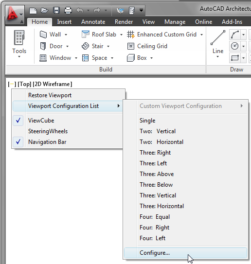 You can also temporarily maximize the currently active viewport and then restore the previous viewport configuration using this first menu.
The second string allows you to quickly select a Model View to restore, either preset or custom, as well as access to the View Manager. The name of the current View direction or Model Space View (if current) is displayed in the second string, for easy reference while you work.

The third string displays the name of the current Visual Style, and the menu allows you to set a different Visual Style current (predefined or custom) or to open the Visual Styles Manager.
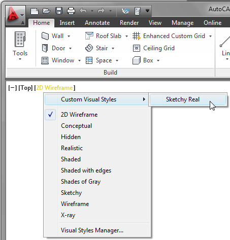
The VPCONTROL System Variable controls the display of the In-Canvas View Controls. Set it to Off (0) to hide the controls. Set it to On (1) to display the controls. It is stored in the registry, so the setting will hold for all drawings.
With TILEMODE set to 0, you will not see the View Controls unless you maximize a viewport on a Layout "tab".
March 26, 2011
ACA 2012 Enhanced Feature - Column Grids
Two improvements to the Column Grid feature have been added in the 2012 release.
Automatic Labeling of Custom Column Grids
With the linework you wish to convert to a custom Column Grid drawn, on the Home ribbon tab, on the Build panel, select the arrow icon at the right side of the Enhanced Custom Grid split button and choose the Custom Grid Convert tool. (As always, click on an image to see a full-size version. Use the Back button in your Browser to return here.) Following the Command: line prompts, select the linework to be converted. The next prompt asks you to specify the label extension distance. Accept the default value, enter a new value or type "N" (No labels command option) if you do not want to add labels automatically at this time. Type "Y" to erase the selected linework or "N" to keep it, and press ENTER to end the command.
 The custom grid will be created, and labels will be added at the ends of the grid lines, if you did not choose the No labels command option. Notice, however, that the labels all have "-" as a default value.
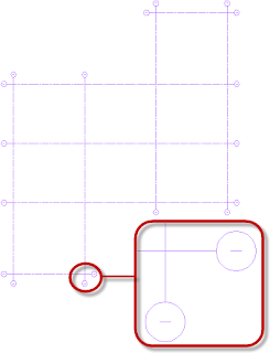 Note: If you did choose the No labels option when creating the Column Grid, you can add labels to it by selecting it and, on the Column Grid contextual ribbon tab, on the Label panel, choosing the Add Labels tool.
With the new, default-labeled custom Column Grid selected, on the Column Grid contextual ribbon tab, on the Label panel, choose the Edit Labels tool. You can now pick a single grid line or a series of grid lines that are to be sequentially numbered, starting with the one to receive the lowest value. When you are done selecting, press ENTER and then enter the value for the first (lowest) grid line and press ENTER to change those values.
The prompt will repeat, so you can pick a second grid line or series of grid lines, starting with the lowest value, and label those as well. When you are done labeling grid lines, press ENTER to end the AecCustomColumnGridLabelEdit command.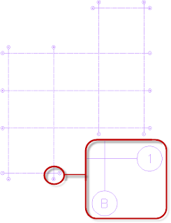
The value you enter for the label can be alphabetic or numeric; either will be incremented when you select a series of grid lines. You can also enter something like "1.1" and choose a series of grid lines and get "1.1", "1.2", 1.3", etc. You can use the Edit Labels tool at any time in the future to edit the values of a single grid line or a series of grid lines.
Labels are automatically added to both ends of each grid line. You can ERASE any labels you do not want to keep.
Enhanced Custom Grids
You can now use an existing regular Column Grid or Enhanced Custom Grid as the starting point for a new Enhanced Custom Grid. On the Home ribbon tab, on the Build panel, choose the Enhanced Custom Grid tool. In the Column Grid dialog, click on the Set From button,
 and then choose the desired Column Grid. The parameters of the selected grid will populate the Column Grid dialog as a starting point for your new Enhanced Custom Grid. A non-enhanced custom Column Grid (created from linework) can not be selected as the "Set From" object.
Automatic Labeling of Custom Column Grids
With the linework you wish to convert to a custom Column Grid drawn, on the Home ribbon tab, on the Build panel, select the arrow icon at the right side of the Enhanced Custom Grid split button and choose the Custom Grid Convert tool.
 (As always, click on an image to see a full-size version. Use the Back button in your Browser to return here.) Following the Command: line prompts, select the linework to be converted. The next prompt asks you to specify the label extension distance. Accept the default value, enter a new value or type "N" (No labels command option) if you do not want to add labels automatically at this time. Type "Y" to erase the selected linework or "N" to keep it, and press ENTER to end the command.
 The custom grid will be created, and labels will be added at the ends of the grid lines, if you did not choose the No labels command option. Notice, however, that the labels all have "-" as a default value.
 Note: If you did choose the No labels option when creating the Column Grid, you can add labels to it by selecting it and, on the Column Grid contextual ribbon tab, on the Label panel, choosing the Add Labels tool.
With the new, default-labeled custom Column Grid selected, on the Column Grid contextual ribbon tab, on the Label panel, choose the Edit Labels tool.
 You can now pick a single grid line or a series of grid lines that are to be sequentially numbered, starting with the one to receive the lowest value. When you are done selecting, press ENTER and then enter the value for the first (lowest) grid line and press ENTER to change those values.
The prompt will repeat, so you can pick a second grid line or series of grid lines, starting with the lowest value, and label those as well. When you are done labeling grid lines, press ENTER to end the AecCustomColumnGridLabelEdit command.

The value you enter for the label can be alphabetic or numeric; either will be incremented when you select a series of grid lines. You can also enter something like "1.1" and choose a series of grid lines and get "1.1", "1.2", 1.3", etc. You can use the Edit Labels tool at any time in the future to edit the values of a single grid line or a series of grid lines.
Labels are automatically added to both ends of each grid line. You can ERASE any labels you do not want to keep.
Enhanced Custom Grids
You can now use an existing regular Column Grid or Enhanced Custom Grid as the starting point for a new Enhanced Custom Grid. On the Home ribbon tab, on the Build panel, choose the Enhanced Custom Grid tool.
 In the Column Grid dialog, click on the Set From button,
 and then choose the desired Column Grid. The parameters of the selected grid will populate the Column Grid dialog as a starting point for your new Enhanced Custom Grid. A non-enhanced custom Column Grid (created from linework) can not be selected as the "Set From" object.
March 22, 2011
ACA 2012 New Feature - Corner Windows

One of the new features added to AutoCAD® Architecture 2012 is one for creating corner windows. An easy way to do so has been on the wishlist for some time, and now it is here. Corner Windows make use of "regular" ACA Window Styles, which now feature some added properties on the Dimensions tab in the Frame area.
 As you can see in the image above, you have the option of specifying butt glazing at the corner. If this toggle is unchecked, you will get a frame at the corner, and you can specify the exposed inside width of the frame (dimension "K"). Window Styles from previous releases will default to having the Butt Glazing at Corner toggle checked (K - Width of 0). The out-of-the-box "regular" Window Styles also have the Butt Glazing at Corner toggle checked. While there is no reason to create a separate Window Style with "Corner Butt Glazing" in the name, the out-of-the-box content includes a "Corner Butt Glazing - Picture" Window Style that is used by the Tool palette tool of the same name.
Corner Windows are placed using a new command, WINDOWCORNERADD. You can create your own Corner Window Tool palette tool by copying one of the out-of-the-box tools and modifying the properties to use your desired style. In addition to the out-of-the-box style-specific tools on the Corner Windows palette in the Design Tool Catalog (under Doors and Windows),
 you can find a generic Corner Window tool in the Stock Tool Catalog, under Architectural Object Tools. You can also invoke the WINDOWCORNERADD command on the Home ribbon tab, on the Build panel, by clicking the down arrow icon at the right side of the Window split button and choosing the Corner Window tool.
Corner Windows must be placed by selecting a Wall; they can not be inserted as free-standing objects, like "regular" Windows. The Wall selected must also be intersected by another Wall, and both must clean up to form an "L" corner; the angle need not be 90 degrees. "T" or "X" intersections will not work. Curved Walls are also not currently supported. If you try to place a Corner Window and nothing happens when you select a Wall, check the Command: line for helpful messages such as "No valid wall intersection found for selected wall." to help you figure out why the Corner Window is not being placed.

After selecting the first Wall, a preview of the Corner Window will appear on screen. If there are valid corners at each end, you can move your cursor closer to the desired end to have the preview appear at the correct end. When adding a Corner Window, you will find that instead of being able to edit the usual Width property (Dimension A, which is still there, but not editable), you now have two new properties, Width 1 (Dimension E) and Width 2 (Dimension F), which allow you to control the width of each leg of the Corner Window. Width 1 applies to the leg within the selected Wall, Width 2 applies to the other Wall. The Width property will display the sum of the Width 1 and Width2 values.
 In the image above, the horizontal Wall was selected, and the dynamic dimension for Width 1 is initially active. You can set the widths using the dynamic dimensions or by editing the properties on the Design tab of the Properties palette. Use the Opening measure property to choose whether the specified Width 1 and Width 2 values are measured to the Outside of opening, Center of opening or Inside of opening.
Standard Sizes remain the same as before - when placing a Corner Window, the width dimension specified is used for both legs.
Corner Windows can be tagged and scheduled just like "regular" Windows". The Width automatic property source will show both widths, separated by " x ".

Corner Windows can be grip edited similar to "regular" Windows, with some Corner-Window-specific changes. The arrow-shaped Flip grip located at the jamb will swap the Width 1 and Width 2 legs. This does not just swap the width values, but actually moves the Width 1 leg to the other Wall, as if it had been selected first.
 The square Location grip offers a different first option. Instead of "Move along" Wall, which makes no sense for a Corner Window, it offers "Specify wall corner", which allows you to move the Corner Window to any other valid "L" corner Wall intersection, even one involving two different Walls.
Cautions
Corner Windows should not be used in projects where any other team members are not on the 2012 release. While ACA 2012 uses the AutoCAD® 2010 file format and ACA 2010 and 2011 will be able to open the file, neither of those releases will support the proper display of Corner Windows and you will get a "regular" Window, with the width equal to the sum of the center of opening values of Width 1 and Width 2, anchored to the Width 1 Wall at the time it was saved in 2012 and hanging over the end of the Wall, as seen in the image below.
 Schedules created in 2012 with Corner Windows will also show undesired results when opened in 2010 or 2011. (The Width column will show like a formula property with an error, displaying the entire formula used to calculate the Width value.) In limited testing, it appears that opening/editing/saving in 2011 and reopening in 2012 causes no harm, but you will want to test that in your own environment and with the sorts of edting you expect to do before relying on it being safe.
The openings created by Corner Windows are not taken into consideration when using the Offset or Center options when placing other opening objects (Doors, Windows, Openings, Door/Window Assemblies) in a Wall that has a Corner Window. This is not the behavior I expected, so you will want to keep that in mind.
Any type of Window Style can be used as a Corner Window, but it may not be appropriate for all types. For example, you can set up a butt-glazed Glider Peak Corner Window, but that does not mean you should (nor does it mean it could be built).

Subscribe to:
Posts (Atom)