
Showing posts with label Viewport. Show all posts
Showing posts with label Viewport. Show all posts
July 18, 2018
Revit: Multi-Line Viewport Titles on Sheets
I was asked about this today, and decided to record the solution in a blog post, for future reference. Viewport Titles in Revit® will wrap onto a second line when the length exceeds what will fit, based on the length of the label in the Title Family, but often the user wants control over where the wrapping occurs. If your office protocols allow for using the Title on Sheet property of a Viewport for the title that is shown on the Sheet (rather than using the View Name), then you can set a line break at the cursor location in the Title on Sheet property edit box in the Project Browser by pressing CTRL+ENTER.
 And, no, there is no significance to the contents of the Drafting View that I used as my test case, shown in the image above. They are just some semi-random Detail Lines drawn so that there would be something to see when the Drafting View was placed on a Sheet.


January 12, 2012
ACA: Model Views and Annotation Scale
I made an interesting discovery yesterday, that may explain why I have occasionally had issues with viewports where the viewport scale and the annotation scale for the viewport are different. I suppose most people are a little more laid back than I am, and tend to draw on the Model "tab" without a lot of regard for how things will end up on the final sheet, and then compose the sheet on a Layout "tab" by eyeballing the corner points of the viewport, pan model space to get the target area roughly centered, use the scale control to set the viewport scale and then pan and/or adjust the viewport extents to suit. I like to think about how what I am drawing will eventually appear on a sheet, and work out how much of a sheet will be required for the drawing at hand. This often results in a non-plotting polyline in model space defining the extents of a particular drawing or detail, and I generally create a Model View of those extents, so that I can later create a viewport of the corresponding dimensions and restore that Model View and be done.
Yesterday's discovery was that I finally noticed that Model Views retain the annotation scale that is current at the time the Model View is created (when using the VIEW command). I did this while using ACA 2010; it may also occur in 2008 and/or 2009.
 In the image above, you can see a Model View that I created of the area bounded by the yellow rectangle. This area is intended to be shown at 1/2" = 1'-0" (1:24) on a sheet. I "forgot" to change the annotation scale from the initial default of 1/8" = 1'-0", however, and so the Annotation Scale property of the Model View is 1/8" = 1'-0".
After drawing an appropriately sized viewport on a Layout tab and using the VIEW command to restore the Model View I created in that viewport, the viewport scale is correctly reported as 1/2" = 1'-0" on both the Viewport Scale control on the Drawing Window Status bar and on the Design tab of the Properties palette.
 The Properties palette also reveals that the annotation scale associated with that viewport is the 1/8" = 1'-0" that was saved with the Model View. In most cases, having different viewport and annotation scales is not desirable. Note also that if you restore the Model View on the Model tab, the annotation scale will also be changed to that saved with the Model View. If the area is meant to be plotted at a particular scale, having that scale saved with the Model View would help automate getting the right scale associated with annotative content added as well as getting the the right scale when restoring the Model View in a viewport. So I am making a mental note to try to remember to set the annotation scale prior to creating a Model View. But can a Model View created with an incorrect annotation scale be fixed?
Unfortunately, the View Manager dialog does not provide a way to change the Annotation Scale property once the a Model View is created. You can rename the Model View, update the layer snapshot saved with the view (if any) and edit the boundaries of the Model View, but, as you may be able to tell from the gray background in the first image, the Annotation Scale property is not editable. I had hoped that while editing boundaries, that I would be able to change the annotation scale using the control on the Drawing Window Status bar, but that control is disabled when editing boundaries. In order to change the scale, you have to recreate/redefine the Model View, with the correct annotation scale set current prior to the redefinition. This is a fairly straightforward process, but it does require you to reselect the Model View boundaries.
Yesterday's discovery was that I finally noticed that Model Views retain the annotation scale that is current at the time the Model View is created (when using the VIEW command). I did this while using ACA 2010; it may also occur in 2008 and/or 2009.

After drawing an appropriately sized viewport on a Layout tab and using the VIEW command to restore the Model View I created in that viewport, the viewport scale is correctly reported as 1/2" = 1'-0" on both the Viewport Scale control on the Drawing Window Status bar and on the Design tab of the Properties palette.

Unfortunately, the View Manager dialog does not provide a way to change the Annotation Scale property once the a Model View is created. You can rename the Model View, update the layer snapshot saved with the view (if any) and edit the boundaries of the Model View, but, as you may be able to tell from the gray background in the first image, the Annotation Scale property is not editable. I had hoped that while editing boundaries, that I would be able to change the annotation scale using the control on the Drawing Window Status bar, but that control is disabled when editing boundaries. In order to change the scale, you have to recreate/redefine the Model View, with the correct annotation scale set current prior to the redefinition. This is a fairly straightforward process, but it does require you to reselect the Model View boundaries.
- With the Model tab current, set the desired annotation scale.

- Start the VIEW command. In the View Manager, select the Model View to be recreated in the left pane, and then select the Name in the middle pane and copy the name to the clipboard. (You can skip this step if you are willing to type in the exact view name in the next step.)

- Click the New button. In the New View / Shot Properties dialog, paste (or type) the view name in the top edit box. Make any other changes to the settings in the dialog as desired.
- Click the Define view window button (or select the Define window radio button) and define the area of the Model View.

- Click OK in the New View / Shot Properties dialog. Choose Replace in the View - Already Exists dialog.

- In the View Manager dialog, note that the Annotation Scale property for the redefined Model View now matches the current, desired annotation scale.

- Click OK to dismiss the View Manager and register your changes.
- Return to the Layout tab and restore the redefined Model View in the viewport. Notice that now that the correct annotation scale is associated with the Model View, the viewport gets the correct annotation scale when the Model View is restored.


December 27, 2011
ACA - Multiple Cut Planes in One Sheet
You may have a situation where you would like to show the same plan area more than one time on the same sheet, with the same Display Configuration, but with two different cut planes. For example, you might have a door with sidelights and transom, and you might want to show a plan view cut at the usual cut plane height, through the door, along with a plan view cut through the transom.
 This can be done, but you need to remember that the cut plane height is set in the Display Configuration. Recent releases of ACA have had a control on the Drawing Window Status bar that lets you change the value of the cut plane without having to edit the current Display Configuration through the Display Manager.
 Someone unfamiliar with the way the cut plane is set in the Display Configuration might think that you could set up two viewports of the same plan area
 and make model space active in one and simply change the cut plane for that viewport. Because both viewports use the same Display Configuration (High Detail in the example shown), using the Cut Plane Control to change the cut plane height in one viewport
 changes the cut plane in both viewports.

Changing the cut plane back to 3'-6" will, of course, change it back in both viewports. In order to have different global cut planes for the two plans, you will need to have two separate Display Configurations. This is easily done in the Display Manager:


Changing the cut plane back to 3'-6" will, of course, change it back in both viewports. In order to have different global cut planes for the two plans, you will need to have two separate Display Configurations. This is easily done in the Display Manager:
- With model space in one of the plan viewports active, on the Manage ribbon tab, on the Style & Display panel, choose the Display Manager tool.

- In the left pane, select the Configurations node under the current drawing.
- In the right pane, right click on the current Display Configuration, which will appear in bold type, and choose Copy from the context menu.

- In the right pane, right click in the white area below the list of Configurations and choose Paste from the context menu.

- In the left pane, expand the Configurations node and select the copied Display Configuration - in the expample, High Detail (2).
- In the right pane, on the General tab, rename the Display Configuration with a more meaningful name, if desired.

- On the Cut Plane tab, set the desired Cut Height for the cut plane of the new Display Configuration.

- Click OK in the Display Manager to accept the changes and return to the drawing.
- Set the new Display Configuration current in the plan viewport where you want the new cut plane applied.


March 30, 2011
AutoCAD 2012 New Feature - In-Canvas View Controls
The In-Canvas View Control is a new feature added to AutoCAD® 2012, so it is also available in ACA 2012. When combined with the tools on the Navigation Bar and the ViewCube, you really do not need to tear off the View panel from the Home ribbon tab anymore.
Appearing at the top left corner of the drawing area on the Model "tab" (TILEMODE 1) and consuming a minimum of screen real estate, there are three text strings enclosed in square brackets; a left click on one of the strings gives access to popup menus related to that particular view control. The first string - either a "-" (one viewport displayed) or a "+" (multiple viewports displayed - allows you to control the visibility of the ViewCube, SteeringWheels and Navigation Bar as well as access to Viewport configurations, including any custom configurations you may have created. You can also temporarily maximize the currently active viewport and then restore the previous viewport configuration using this first menu.
The second string allows you to quickly select a Model View to restore, either preset or custom, as well as access to the View Manager. The name of the current View direction or Model Space View (if current) is displayed in the second string, for easy reference while you work.
The third string displays the name of the current Visual Style, and the menu allows you to set a different Visual Style current (predefined or custom) or to open the Visual Styles Manager.
The VPCONTROL System Variable controls the display of the In-Canvas View Controls. Set it to Off (0) to hide the controls. Set it to On (1) to display the controls. It is stored in the registry, so the setting will hold for all drawings.
With TILEMODE set to 0, you will not see the View Controls unless you maximize a viewport on a Layout "tab".
Appearing at the top left corner of the drawing area on the Model "tab" (TILEMODE 1) and consuming a minimum of screen real estate, there are three text strings enclosed in square brackets; a left click on one of the strings gives access to popup menus related to that particular view control. The first string - either a "-" (one viewport displayed) or a "+" (multiple viewports displayed - allows you to control the visibility of the ViewCube, SteeringWheels and Navigation Bar as well as access to Viewport configurations, including any custom configurations you may have created.
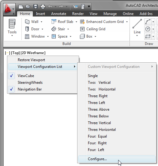 You can also temporarily maximize the currently active viewport and then restore the previous viewport configuration using this first menu.
The second string allows you to quickly select a Model View to restore, either preset or custom, as well as access to the View Manager. The name of the current View direction or Model Space View (if current) is displayed in the second string, for easy reference while you work.

The third string displays the name of the current Visual Style, and the menu allows you to set a different Visual Style current (predefined or custom) or to open the Visual Styles Manager.
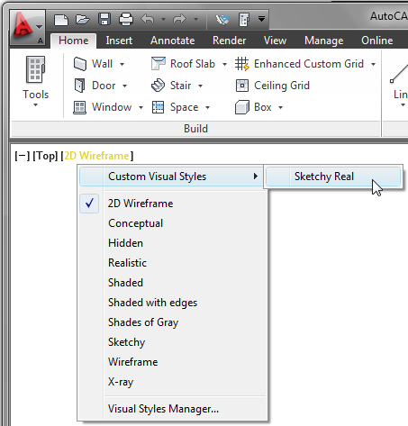
The VPCONTROL System Variable controls the display of the In-Canvas View Controls. Set it to Off (0) to hide the controls. Set it to On (1) to display the controls. It is stored in the registry, so the setting will hold for all drawings.
With TILEMODE set to 0, you will not see the View Controls unless you maximize a viewport on a Layout "tab".
May 10, 2007
Cycling Between Viewports in a Layout
Those of you who used Autodesk® Architectural Desktop prior to the introduction of the Customize User Interface (CUI) files in 2006 may recall that the menu file included an "accelerator" for the CTRL+R keystroke combination that would cycle between the viewports in a layout whose extents are at least partially visible on-screen. Those of you who have been using AutoCAD® for many years may also recall that the "original" accelerator was CTRL+V [or ^V in a menu macro], which got supplanted when Windows came along and made CTRL+V "paste".
The ability to cycle through the viewports can be handy when you have overlapping viewports and the program decides the one you want is "underneath" the one you do not want, and is essential if you have an "underneath" viewport that is entirely within the boundaries of another viewport. For whatever reason, the CTRL+R accelerator did not get incorporated into the ADT.cui file, so users of 2006 and later may find they no longer can cycle through viewports using CTRL+R. The good news is nothing else has been assigned to CTRL+R, and it is not difficult to add the CTRL+R functionality back.
In CUI files, the old accelerators are now called Shortcut Keys and are found under the Keyboard Shortcuts category of a given CUI. You can add Shortcut Keys to the main CUI or any partial CUIs you may have loaded; if you have a separate CUI for your company standard menu items or for your personal use, you may want to add the CTRL+R Shortcut Key there, to aid in migrating to future releases. The Help contains instructions for how to add a Shortcut Key, and there is even a video in the 2007 Help for those of you who are visually oriented. You can find this by navigating here: AutoCAD Help > Customization Guide > Customize the User Interface > Add Shortcut Keys and Temporary Overrides. In 2006, click on the Procedures tab, then select the "To create a shortcut key" link. In 2007, the video is on the "Add Shortcut Keys and Temporary Overrides" page.
For those who have an allergic reaction to the Help, or who find the fact that the instructions are written around the ACAD.cui, not the ADT.cui too annoying to bear, the balance of this article covers the specifics of adding the ^V macro as a Shortcut Key and assigning the CTRL+R keystroke to it. The first thing you will need to do is open the Customize User Interface dialog. Type CUI at the Command: prompt. If you hate keyboarding and want to use a pulldown menu, you will not be able to use the Tools pulldown, as noted in the Help [unless you have added that from the ACAD.cui file]. If you have added the CAD Manager pulldown menu [Window > Pulldowns > CAD Manager Pulldown] you can start the CUI command from there, as shown below. [As always, you can view a full-size version of reduced size images by clicking on the image.]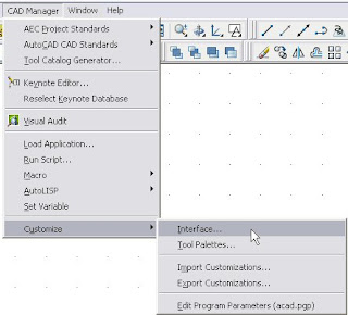
Set the Customize tab active, if it is not already current. The upper left pane of the Customize tab lists the CUI files that are loaded. You can choose to show all CUI files, or focus on one using the dropdown list at the top of the pane. Expand the CUI in which you want to add the CTRL+R Shortcut Key and then expand the Keyboard Shortcuts category, as shown below. You will not see the large red arrow, which I added to the image for emphasis.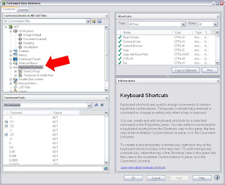
Here is a tip for those of you who have fully embraced the AutoCAD® Architecture/Autodesk Architectural Desktop mindset of right-clicking to do just about anything. In this case, it will not work. You can right click on either "Keyboard Shortcuts" or "Shortcut Keys" and a context menu will obediently appear, but there will not be an option to add a new Shortcut Key, as can be seen in the image below.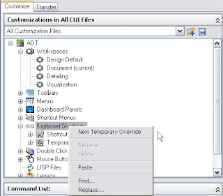
New Shortcut Keys are created by dragging the command you want from the Command List in the lower left pane of the CUI dialog and dropping it onto "Shortcut Keys" in the upper left pane. Fortunately for our example, there is alread a "command" in the Command List, named "CTRL+R", that has the ^V macro assigned to it, so we do not need to add a custom command to the list. Scroll down in the Command List list box until you see the "CTRL+R" command.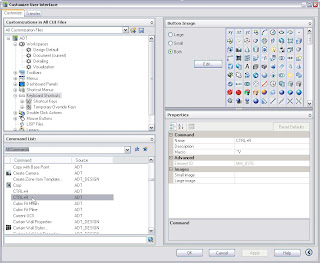
Left click on and then drag the "CTRL+R" command up to "Shortcut Keys" in the upper left pane and drop it there.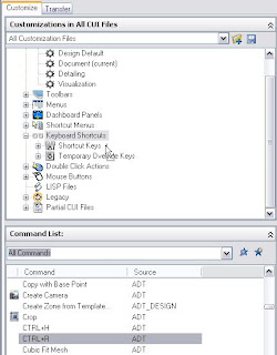
Expand the Shortcut Keys subcategory, if it did not do so automatically while you were dragging and dropping, and then find and select your new "CTRL+R" command on the list of commands. This will change the display on the right side of the Customize tab of the CUI dialog, displaying "Shortcuts" in the upper right pane, with a list of all of the Shortcut Keys commands, and "Properties" in the lower right pane. Since you selected "CTRL+R" command in the upper left pane, it is highlighted in the upper right pane and the Properties pane shows the properties for that command. Notice the horizontal bar in the left column in the Shortcuts pane, rather than the check mark that the other commands have. That is because a keystroke has not been assigned yet.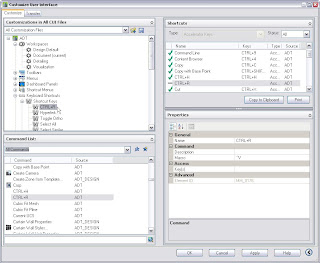
To assign a keystroke, click in the right column next to the "Key(s)" line in the Access category of the Properties pane. An ellipsis button will appear at the right side of that line; select it to open the Shortcut Keys dialog.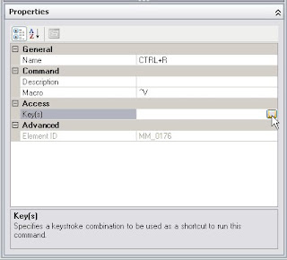
The Shortcut Keys dialog allows you to indicate what keystroke combination you want to assign to this command. Click in the edit box, if the focus is not already there, then press the "CTRL" and "R" keys at the same time, to enter "CTRL+R". The dialog will tell you what command is currently assigned to that keystroke combination, if any. If you are satisfied with the entry, select OK to return to the CUI dialog box.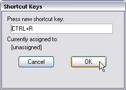
You have now assigned a keystroke combination to the CTRL+R command, and the Shortcuts pane now shows a checkmark in the first column on that line, as well as the assigned keystroke combination in the Keys column. Select the Apply button to save this change to the CUI, if you have additional changes to make, or select OK to save the change and return to the drawing file.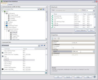
You should now find pressing CTRL+R when model space is active on a Layout with multiple viewports visible on screen will cycle through those viewports. You will want to back up the CUI file in which you made the change, to avoid having to do it again in the future, should you ever "lose" that file.
The ability to cycle through the viewports can be handy when you have overlapping viewports and the program decides the one you want is "underneath" the one you do not want, and is essential if you have an "underneath" viewport that is entirely within the boundaries of another viewport. For whatever reason, the CTRL+R accelerator did not get incorporated into the ADT.cui file, so users of 2006 and later may find they no longer can cycle through viewports using CTRL+R. The good news is nothing else has been assigned to CTRL+R, and it is not difficult to add the CTRL+R functionality back.
In CUI files, the old accelerators are now called Shortcut Keys and are found under the Keyboard Shortcuts category of a given CUI. You can add Shortcut Keys to the main CUI or any partial CUIs you may have loaded; if you have a separate CUI for your company standard menu items or for your personal use, you may want to add the CTRL+R Shortcut Key there, to aid in migrating to future releases. The Help contains instructions for how to add a Shortcut Key, and there is even a video in the 2007 Help for those of you who are visually oriented. You can find this by navigating here: AutoCAD Help > Customization Guide > Customize the User Interface > Add Shortcut Keys and Temporary Overrides. In 2006, click on the Procedures tab, then select the "To create a shortcut key" link. In 2007, the video is on the "Add Shortcut Keys and Temporary Overrides" page.
For those who have an allergic reaction to the Help, or who find the fact that the instructions are written around the ACAD.cui, not the ADT.cui too annoying to bear, the balance of this article covers the specifics of adding the ^V macro as a Shortcut Key and assigning the CTRL+R keystroke to it. The first thing you will need to do is open the Customize User Interface dialog. Type CUI at the Command: prompt. If you hate keyboarding and want to use a pulldown menu, you will not be able to use the Tools pulldown, as noted in the Help [unless you have added that from the ACAD.cui file]. If you have added the CAD Manager pulldown menu [Window > Pulldowns > CAD Manager Pulldown] you can start the CUI command from there, as shown below. [As always, you can view a full-size version of reduced size images by clicking on the image.]

Set the Customize tab active, if it is not already current. The upper left pane of the Customize tab lists the CUI files that are loaded. You can choose to show all CUI files, or focus on one using the dropdown list at the top of the pane. Expand the CUI in which you want to add the CTRL+R Shortcut Key and then expand the Keyboard Shortcuts category, as shown below. You will not see the large red arrow, which I added to the image for emphasis.

Here is a tip for those of you who have fully embraced the AutoCAD® Architecture/Autodesk Architectural Desktop mindset of right-clicking to do just about anything. In this case, it will not work. You can right click on either "Keyboard Shortcuts" or "Shortcut Keys" and a context menu will obediently appear, but there will not be an option to add a new Shortcut Key, as can be seen in the image below.

New Shortcut Keys are created by dragging the command you want from the Command List in the lower left pane of the CUI dialog and dropping it onto "Shortcut Keys" in the upper left pane. Fortunately for our example, there is alread a "command" in the Command List, named "CTRL+R", that has the ^V macro assigned to it, so we do not need to add a custom command to the list. Scroll down in the Command List list box until you see the "CTRL+R" command.

Left click on and then drag the "CTRL+R" command up to "Shortcut Keys" in the upper left pane and drop it there.

Expand the Shortcut Keys subcategory, if it did not do so automatically while you were dragging and dropping, and then find and select your new "CTRL+R" command on the list of commands. This will change the display on the right side of the Customize tab of the CUI dialog, displaying "Shortcuts" in the upper right pane, with a list of all of the Shortcut Keys commands, and "Properties" in the lower right pane. Since you selected "CTRL+R" command in the upper left pane, it is highlighted in the upper right pane and the Properties pane shows the properties for that command. Notice the horizontal bar in the left column in the Shortcuts pane, rather than the check mark that the other commands have. That is because a keystroke has not been assigned yet.

To assign a keystroke, click in the right column next to the "Key(s)" line in the Access category of the Properties pane. An ellipsis button will appear at the right side of that line; select it to open the Shortcut Keys dialog.

The Shortcut Keys dialog allows you to indicate what keystroke combination you want to assign to this command. Click in the edit box, if the focus is not already there, then press the "CTRL" and "R" keys at the same time, to enter "CTRL+R". The dialog will tell you what command is currently assigned to that keystroke combination, if any. If you are satisfied with the entry, select OK to return to the CUI dialog box.

You have now assigned a keystroke combination to the CTRL+R command, and the Shortcuts pane now shows a checkmark in the first column on that line, as well as the assigned keystroke combination in the Keys column. Select the Apply button to save this change to the CUI, if you have additional changes to make, or select OK to save the change and return to the drawing file.

You should now find pressing CTRL+R when model space is active on a Layout with multiple viewports visible on screen will cycle through those viewports. You will want to back up the CUI file in which you made the change, to avoid having to do it again in the future, should you ever "lose" that file.
Subscribe to:
Posts (Atom)