 (As always, click on any image to see the image full size. Use the Back button on your browser to return to the article.)
First, you need to decide how a Window above the cut plane should display. If it is a clerestory Window that is well above the cut plane, you may want to indicate the Window in a plan view, but use different graphics than you would for one that is actually cut by the cut plane, so that it is apparent in the plan view that the Window is above the cut plane. On the other hand, you may want one that is not very far above the cut plane to appear just like others that do intersect the cut plane.
Different Graphics
The out-of-the-box Plan Display Representation for Windows includes "Above Cut Plane" components for the Frame, Sash and Glass, but they are turned off. You can have above-cut-plane Windows display when the Plan Display Representation is active by turning on these components and setting the color, linetype and lineweight to suit your needs. This can be done at the Drawing Default, Style or Object level. Drawing Default settings are best edited in the Display Manager. Style-level settings are most easily edited through the Style Manager, or by selecting the object and editing its style. Object-level settings require selecting the object. Because we are making changes to several components, I will be showing the edits using dialogs.* I will also be applying the display settings as Object-level overrides, to allow me to keep a number of different conditions in the same drawing file; you will need to decide whether you should make the changes at the Drawing-Default level (affecting all Windows without a Style- or Object-level override), Style-level (affecting all instances of that Style that do not have an Object-level override) or at the Object-level (affecting just that instance).
 As shown above, I set an object-level override on the Plan Display Representation of the Window, and turned on the display of the above cut plane components for the frame, sash and glass. I also changed the color, lineweight and plot style to ByBlock and the linetype to HIDDEN2.
If you prefer not to have the Wall Component graphics run through the above-cut-plane Window graphics, you can edit the Plan Display Representation of the Wall, by checking the "Hide Lines Below Openings Above Cut Plane" toggle on the Other tab.

If you would like to have lines at the opening just at the face of the outer component of the Wall, you can turn on the Above Cut Plane component of the Wall. Make certain that the Display Inner Lines Above toggle is unchecked.**

Identical Graphics
If you can find a global cut plane level that will cut through all of your Windows and not adversely affect the display of other objects, the easiest way to get all of your Windows to display identically is to raise the global cut plane to that level.
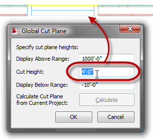
If there is no single global cut plane height that will cut through all Windows, or any such height has unwanted side effects on other objects, you can leave the global cut plane height at your standard height and override the cut plane on Walls. This is done on the Cut Plane tab, by checking the Override Display Configuration Cut Plane toggle, and then entering the desired Cut Plane Height, if you are editing the display settings via dialog, as shown below.

If you are editing on the Display tab of the Properties palette, in the Object Display Properties category, in the Cut Plane subcategory, change the Override cut plane property to Yes and then enter the desired value in the Height property.
If even limiting the cut plane adjustment to Walls with Windows above the global cut plane has unwanted side effects, or you would just prefer not to adjust the cut plane at all, you can still make Windows above the cut plane appear like Windows at the cut plane, by turning on the Frame Above Cut Plane, Sash Above Cut Plane and Glass Above Cut Plane components in the Plan Display Representation for Windows and making the display settings for these components match that of the Frame, Sash and Glass components, respectively.

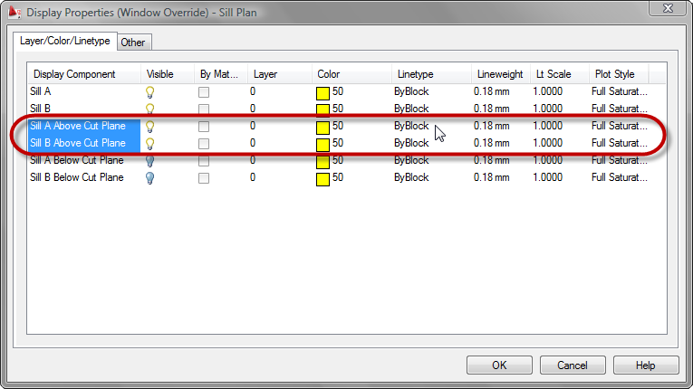
Also turn on the Sill A Above Cut Plane and Sill B Above Cut Plane components and make the display settings match those of the Sill A and Sill B components, respectively.
Finally, edit the display settings of the Plan Display Representation of the Wall, checking the Hide Lines Below Openings Above Cut Plane toggle on the Other tab.

* - You can also make the edits using the Display tab of the Properties palette, but you will have to be able to both select the Window and have the Plan Display Representation active at the same time. To do this, you can either set the Top view direction active with a Display Configuration that uses the Plan Display Representation for the Top view, such as the Medium Detail Display Configuration and temporarily set the Cut Plane high enough to intersect the Window so you can select it, or you can split the Model "tab" into two viewports, setting one to one of the Isometric views in which you can select the Window and setting the other to the Top view direction. Select the Window in the Isometric viewport, then left click in the Top viewport to make it active, and you will have access to the Plan Display Representation and its components on the Display tab of the Properties Palette. You can then select the display level to which the changes are to be applied and then choose/edit each component.

** - The Above Cut Plane component, Display Inner Lines Above toggle and Hide Lines Below Openings Above Cut Plane interact in a similar fashion as the Below Cut Plan component, Display Inner Lines Below toggle and the Hide Lines Below Openings at Cut Plane toggles. See ACA Wall Display Settings at Openings for a detailed description of the interaction.
1 comment:
Wow thanks David, that was really simple. I've never really got those settings and usually just override the wall CP. This would help in ensuring that windows are picked up in scheduling if you are picking in plan view as the high window will show. Excellant post. I'll have to re-read the other one a few more times, that's quite a puzzler but a great post. much appreciated. I know it's just a matter of spending time working thru but there are so many things to work thru.
thanks & cheers
Post a Comment