November 01, 2019

ACA-AMEP: Edit Property Data Via AutoLISP, Part 1

Sometimes you need to make changes to the values of a Property on all or many AEC Objects in a file. If that change can be done programatically (example, in a text-type manual Property, edit the text value, replacing all occurrences of "1ST" with "2ND"), and there are a large number of Objects to process, it may be easier to do so via AutoLISP, than to manually edit each value. This series of articles will show you how to do so.

NOTE: I have only used this technique on manual Properties. I am not certain what would happen if you tried to use this to change the value of an automatic property. I suspect the change may fail, at least in some cases, like formula Properies. Even if it works for some automatic Properties, such as the height or width of a Door, doing so may have unexpected results in the drawing. If you have a use case for trying to edit the values of automatic Properties, please test this thoroughly on copies of files, or files created strictly for testing purposes, not on actual project files, until you are certain there is no harm.

The VisualLISP commands will be used to access the object model. You will also need to operate on vla-objects. If your method of getting the selection set on which to operate results in AutoLISP entity names, these can be converted to vla-objects by using the
(setq obj (vlax-ename->vla-object ename))
function, where obj is the name of a variable holding the vla-object and ename is the name of a variable holding the entity name of the object on which you want to operate.

Getting to the Property value is not a matter of simply querying the object for it. You will need to drill down into the object model. Start with the following code. You can use different variable names if the ones used in the example code here do not conform to your naming standard. Just make certain you substitute your names consistently.
(vl-load-com)
(setq objAcad    (vlax-get-acad-object)  ; AutoCAD Application Object.
      objAecSchd (vla-GetInterfaceObject objAcad (strcat "AecX.AecScheduleApplication" (aecappver)))
                                         ; AecScheduleApplication object.
      oPSets     (vlax-invoke-method objAecSchd 'PropertySets obj)
                                         ; Get PropertySets collection object.
      iPSets     (vlax-get-property oPSets 'Count)
                                         ; Get number of Property Sets in the PropertySets collection object.
      iPSet  0                           ; Initialize Property Set counter.
) ;_ End setq.

Here is what is happening in that code:
  • The (vl-load-com) function loads the VisualLISP functions, if they are not already loaded. If they are loaded, it does nothing.
  • The first item in the setq function gets the AutoCAD object. This is then used to get the AEC Schedule Application object. This object is version-specific, so I use a subroutine I put together to return the version string, called AECAPPVER. You can find the code for that routine in this previous article. The article was updated to support versions through 2020.
  • The third item in the setq function uses the PropertySets method of the AEC Schedule Application object to get the PropertySets collection for the object on which we want to operate (which is held in the obj variable).
  • The final two items in the setq function determine the number of Property Sets that are in that collection, and initializes a Property Set counter to 0, which is the index of the first Property Set in the collection.

Next article in the series.

October 29, 2019

Dynamo: String Concatenation 2

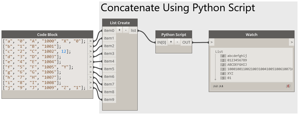
I had some time and tested some scenarios using the "successful" nodes for concatenating a list of strings shown in this previous post and noticed that the concatenation will still work if the lists do not all have the same numbers of strings. It still concatenates the first item in each list, and so on; once the shortest list runs out of items, it simply does not contribute anything to subsequent concatenations. The process will fail, if the items in the source lists contain anything other than strings, however. That is not a particular surprise (to me, anyway), but a combination of being able to handle non-text items in the source lists without throwing an error/crashing the graph and wanting to see just what it would take to write a Python Script node that could process a variable number of lists of strings prompted me to try it.

A List Create node is still necessary to make a single list of lists to serve as the input, so that the Python Script node need only have one input, but the List.Transpose and List.Flatten nodes can be eliminated.


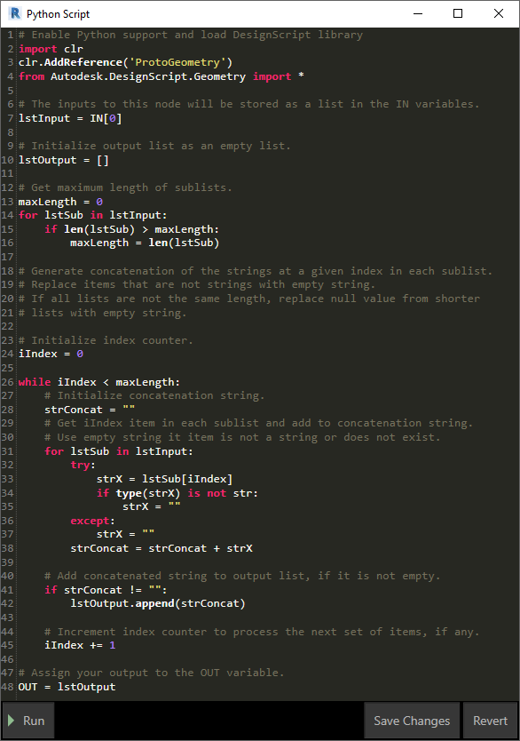
The Python code is fairly straightforward.
  • The input list of strings is assigned to lstInput, and lstOutput is set up as an empty list, to receive the list of concatenated strings, which will be the output of the node.
  • A for statement examines the length of each of the sublists in lstInput, to determine the maximum list length (maxLength). This is used to set the number of times the concatenation code needs to be run: once for every item in the longest list.
  • An index counter, iIndex, is initialized to the first index, 0.
  • A while statement is used to process the lists, once for each item on the longest list.
  • On each pass through the while code, a variable to hold the concatenated string from that pass (strConcat) is initialized as an empty string.
  • Then, for each sublist in lstInput, strX is set to the string at the current index being processed. This is done in a try statement, so that the code does not fail when a shorter list has no item at the current index. If a value is returned, an if statement verifies that it is a string. If not, strX is reset to an empty string. If a value is not returned to strX, the except statement sets strX to an empty string.
  • The string value in strX is then added to the end of strConcat, and the for statement is rerun for the next sublist, until all sublists have been processed.
  • With the fully processed concatenated string in hand, an if statement checks the value, to see if it remains an empty string. If not, the string is appended to lstOutput. If it is empty, no action is taken.
  • Finally, the index counter (iIndex) is incremented, and the while statement is run again, provided that iIndex remains less than the length of the longest sublist (maxLength).
  • Once the while statement has been run once for each item in the longest list, the list of concatenated strings in lstOutput is sent to the output of the node.
It turns out that the code required to handle a variable number of lists of strings was not as complicated as I thought before I wrote it. For situations where I am certain that the lists of strings to be concatenated will in fact be lists of strings, I probably would use the out-of-the-box nodes shown in the previous article, as it is easier to read (no "magic" black box of Python code doing who knows what), but in cases where the lists might not all be lists of strings (user inputs?), I might choose to use the Python Script node rather than checking the lists of strings to verify that all items are strings.

October 25, 2019

Dynamo: String Concatenation

This may be basic and blindingly obvious to more experienced Dynamo users, but this is something with which I have struggled for some time, and now that I have finally sorted it out, I wanted to document it here for easy future reference.

The String.Concat node in Dynamo provides an easy way to combine two or more strings into one string.
When each item fed into the stringn inputs is an individual string, all of the strings are combined into one string, and that is the output of the node, as shown in the image above.

I rarely need to combine one set of individual strings, however; I almost always have lists of strings to process. Perhaps there is some deficiency in the way I think, but when I first tried to use the String.Concat node with lists of strings, I was expecting that the the result would be a list of concatenated strings, and that the value at each index in that list would be the concatenation of the strings at that same index in each of the input strings. Unfortunately, that is not what the node does.
As you can see, the result is a list of strings, one for each input, with the strings in each input concatenated together. I was expecting ["abc", "123"], but I got ["a1", "b2", "c3"]. This seems contrary to what it does when single strings are input - at least, it does to me. I found this quite frustrating, and on at least one occasion, wrote a quick Python Script node to do the concatenation the way I wanted it. But that quick Python Script did not allow for varying numbers of input lists of strings (I suppose it could be written to do so, but that would no longer be "quick"). I could not understand why the String.Concat node would not do what I wanted, and could not believe that the way it works is what most users would want, most of the time.

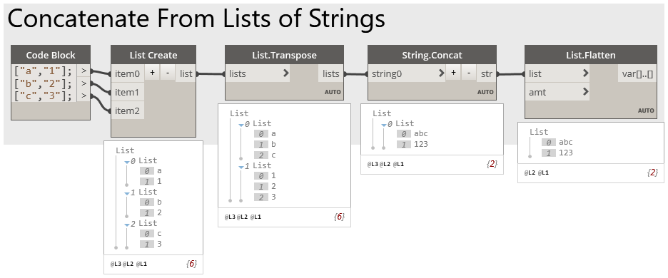
Once I set aside my frustration and started thinking again, it dawned on me that all I needed to do was rearrange my input data to work with the way the String.Concat works, and while that requires a few extra nodes, it is fairly easy to do. (Click on the image below to see it full-size.)
By using the List Create node, I combined my individual lists into one list of lists. The List.Transpose node then transforms that list of lists into another list of lists, in which each sublist has a list of the items from the same index in the original sublists. So each sublist has a list of the strings I want combined into one string, and this can be fed into the String.Concat node to get the desired concatenation. The output of the String.Concat node ends up having the list of concatenated strings nested in a list, so adding a List.Flatten node using the default flatten amount (totally flatten) results in a list of the concatenated strings, which was my desired result.

September 11, 2019

ACA: Rotation Property for Multi-View Blocks

Robin Capper made the observation in a post to the AutoCAD Architecture Forum that Multi-View Block References do not have an automatic property for Rotation, unlike Block References or MInsert Blocks. I was surprised to see that was true, but figured that a Formula Property would be able to get the value, if it is exposed.

A quick check using the "vlax" functions in AutoLISP verified that the Rotation property is exposed in the API. I have gotten a little rusty on the specifics of accessing data from the drawing in a Formula Property, but after a few searches of this blog, I had enough to refresh my memory and come up with this as the formula for a Formula Property in a Property Set Definition that applies to Multi-View Block References:
pi = 3.141592653589793238462643383
Set acadApp = GetObject(,"AutoCAD.Application")
Set mvbObj   = acadApp.ActiveDocument.ObjectIDToObject( [ObjectID] )
RESULT = CDbl(mvbObj.Rotation * 180.0 / pi)

Before you create the Formula Property, add an instance of the ObjectID automatic property to the same Property Set Definition. In the formula, [ObjectID] needs to be a reference to that property, created by double clicking on the property in the Insert Property Definitions area of the Formula Property Definition dialog. You cannot just type [ObjectID] in the formula. When the reference is added, it will have a light gray background.

The angle value obtained from the Multi-View Block Reference object is in radians; I chose to convert that value to degrees. If radians will suit your needs better, you can delete the first line and, in the RESULT line, delete * 180.0 / pi. After posting my reply, I came across a better way to generate the value for pi:
pi = 4 * Atn( 1.0 )

August 29, 2019

Revit: Yes/No Parameter Values

You might think that a Yes/No parameter can only have two values:
  • Yes
  • No
But, in fact, there can be three values:
  • Null
  • Yes
  • No
Null will only occur when a Yes/No parameter is first placed on an object, such as when you add an instance-based Yes/No Project Parameter to one or more categories in your project (for this example, Walls). After doing so, you will see something similar to this:
In the image above, the HasToggle Yes/No parameter has just been added to Walls. The toggle itself (the square in the value column) shows a check mark, but the check mark and the square are grayed out. You might think this means that the parameter is disabled, but if you look at the parameter name, it is not grayed out. Contrast this to the Enable Analytical Model parameter a few rows below the HasToggle parameter, where both the parameter name and the square are grayed out. The Enable Analytical Model parameter is disabled, because the Structural parameter (another Yes/No parameter) is not checked. The HasToggle parameter is enabled, but the toggle is grayed out to indicate that a value for the parameter has not yet been chosen, so the value is at its initial "Null" state.

Left clicking on the toggle will set the value to Yes, and the toggle is no longer grayed out.

Left clicking on the toggle again will change the value to No.

Once the toggle is clicked and an initial value set, you cannot set it back to Null, so, in operation, there are only two values, Yes and No, but you need to be aware that parameter can have that third value, Null, as that can have an impact on your model. For example, suppose the HasToggle parameter is used to drive two filters, that will be used to change the display of Walls in a view.
In the image above, you can see that two filters have been created, HasToggle-Yes and HasToggle-No, along with the properties of the HasToggle-Yes filter. The filter applies to Walls, and will select all Walls where the HasToggle parameter is set to Yes. The HasToggle-No filter properties are identical, except the filter collects Walls whose HasToggle parameter value is set to No. In the LEVEL 1 FLOOR PLAN View, these filters have been applied and an unattractive combination of colors has been assigned to the Cut Lines and Patterns, to make it obvious that the filter has been applied.

In the image below, you can see eight Walls in the LEVEL 1 FLOOR PLAN View. Two have had the HasToggle parameter set to Yes (checked), two have had the HasToggle set to No (unchecked) and the other four remain in the initial Null state. The Null Walls are not affected by either filter, because the value of the HasToggle parameter is neither Yes nor No.

August 27, 2019

AEC Answer Day - September 24, 2019


Another installment of Autodesk Answer Day, focused on AEC-related products, will take place in the the following forums:
  • English-language Users, 6:00 am (September 24) to 2:00 am (September 25) Pacific Standard Time
    • AutoCAD
    • Civil 3D
    • Revit
    • BIM 360
  • German-language Users, 9:00 am to 5:00 pm Central Europe Time (September 24)
    • AutoCAD Produktfamile - Deutsch
    • Revit - Deutsch
    • Inventor - Deutsch
    • Fusion 360 - Deutsch
    • EAGLE - Deutsch
    • PowerMill, PowerShape, PowerInspect & FeatureCAM - Deutsch
    • BIM 360 - Deutsch
    • 3DS Max - Deutsch
    • Maya - Deutsch forums.

More information, and links to the forums noted above, can be found in this Community Announcement. Stop in that day with your questions and interact with the Autodesk staff that will be taking part.

August 01, 2019

ACA: Got Blips?

Many younger users may have never seen "BLIPS" and many older users have probably forgotten about them. The BLIPMODE command and System Variable have been undefined in AutoCAD® and its verticals since the 2012 release. Back in the day, if BLIPMODE was turned on, every pick would be memorialized on screen with a small, white "+" mark. ZOOMing, PANning or using the REDRAW (yes, that command did have a function once) or REGEN commands would clear these temporary markers from the screen. But if you worked for a while without needing to change your view, you could accumulate a lot of these (and would probably quickly turn BLIPMODE off).

Undefined is not the same as removed, however, and the command is still there, and the System Variable can be accessed via AutoLISP. The System Variable was (is) stored in the Windows Registry, not in the drawing file, so someone could change the setting in the registry, as well. If you find yourself working in a drawing and having blips show up with each left mouse click, even if you remember "BLIPMODE," you will find that neither the command nor the System Variable is "known" by recent versions.

What to do? At the command line, type in the command with a period at the front: .BLIPMODE. The period tells AutoCAD to use the original definition of the command, and suddenly AutoCAD recoginzes it.

Press the ENTER key, and then choose OFF from the command line options.

Or, if there is someone in your office who is overdue for a (mostly) harmless prank, wait for her/him to leave her/his workstation with AutoCAD open. Start a new drawing, type .BLIPMODE, press ENTER and choose ON. Close the new drawing without saving. Discretely slip away, and await your colleague's return, and eventual annoyance. You may want to pop in and offer to fix the issue, before things escalate to an HR-level event. [Use at your own risk.]

July 13, 2019

AUGI Salary Survey, 2019

Help make the survey results more accurate by taking the survey and adding your information: 2019 AUGI Salary Survey.

July 11, 2019

ACA: Schedule Tag Background Mask

I suppose I must have known about this at some time in the past, but having never made use of it, it slipped my mind. The other day, I needed to make some Schedule Tags to replace some attributed Block References. The Attribute Definitions in the Block References had background masking turned on, so that they could be placed on top of other linework and the mask would assure that the contents of the attribute remained readable.

I made use of the graphics from the Block Reference and ran it through the DefineTag command to create the Schedule Tag Multi-View Block reference. I was hoping that the background mask on the Attribute Definition would be respected in the Schedule Tag, but it was not. An internet search turned up this Autodesk Knowledge Network Article, allowing me to re-learn what I had probably forgotten. You create an AEC Polygon Style to use for the background mask; on the Other tab, check the Use Background Mask toggle.

If you do not want the border of the AEC Polygon to plot, go to the Display Properties tab and create a Style Override for the Model Display Representation. In the override, turn off the visibility of the Exterior Edge component. (Do the same for the Model Screened Display Representation if you use that in views that include the Schedule Tags.)

Place an AEC Polygon instance using the Style you just created as part of the graphics you select for the DefineTag command. Be sure to select the AEC Polygon first, and then the other graphics, so that the other graphics are not masked by the AEC Polygon.

In the image below, the Door Tags have had a masking AEC Polygon placed behind the other graphics, and that AEC Polygon is masking out the color fill of the Space and the swing of the Door that is behind the Tag.

July 03, 2019

ACA: Open Dialog Does Not Show - But FILEDIA Is Set to 1

I had a report that the AutoCAD® Architecture Open dialog was not showing up when the OPEN commmand was being used. First thing I checked was the value of the FILEDIA System Variable, but it was set to 1, and there were no prompts on the Command Line when running the OPEN command.

I found the solution for this case in an Autodesk Knowledge Network article, Dialog windows do not display and the program appears to freeze, which offers several suggestions for resolving the issue. Having already done the first one (FILEDIA), I tried the second one - holding SHIFT+WINDOWS KEY and then pressing the LEFT or RIGHT ARROW KEY. That keystroke combination moves the current window from one screen to the next, and it did bring the Open dialog back onto one of the two active monitors.

The user's computer is a laptop, which was docked and closed, but perhaps the dialog was hiding out on the laptop monitor? Wherever it was, the issue was resolved, and I was glad to not have to resort to the last suggestion, editing the Windows Registry.