Here are a couple of new things that I became aware of today. I thought I would post links here in case others have not heard of these yet.
FAQ for Autodesk® Software Rental
You have to be on subscription to take advantage of the following Autodesk® Exchange application:
Autodesk® Remote
July 22, 2013


July 16, 2013
ActiveX and AutoLISP Programming Tip 1
When trying to make use of the AutoCAD® ActiveX® access to the object model through the AutoLISP® "VL" commands, the vlax-dump-object function will likely become one of your best friends. The Help sections on the object model are certainly useful, but as you test bits of code to verify that they work, I have found the vlax-dump-object function invaluable in helping me to understand exactly what properties are available for a given object.
For example, I was trying to update a subroutine I had written some years back that returned certain information about the current AutoCAD® Architecture drawing, including the drawing scale. This was before drawing scale had been added as a feature to the "vanilla" AutoCAD® software, and I had been using a DXF "hack" to get the current drawing scale from (namedobjdict) > AEC_VARS dictionary > AEC_VARS_DWG_SETUP dictionary > 40 group. In more recent releases, the CANNOSCALEVALUE system variable will give you the current annotation scale in a drawing. When Model Space is active in a Layout Viewport, however, it is possible for the viewport scale (magnification relative to Paper Space, which is presumed to be 1:1 when plotted) to be different from the annotation scale, and I wanted to be able to report both scales. By using the vlax-dump-object function in the Visual LISP Console for the ActivePViewport object, I was able to quickly see which properties changed when I changed settings in the drawing, which helped me to understand that the inverse of the CustomScale property of the ActivePViewport object would give me the scale factor for the viewport magnification, and also allow me to sidestep dealing with the enum values reported by the StandardScale (Viewport magnification) and StandardScale2 (viewport annotation scale).
Another thing that I was able to discover by using the vlax-dump-object function was that the Paper Space Viewport does not report all of the properties that other Layout Viewports report. For example, a Layout Viewport object scaled to 1/4" = 1'-0", saved to variable objVpA, might have the following properties, which can be examined using vlax-dump-object:
For the Paper Space Viewport object for that same Layout, vlax-dump-object returns the following:
The LabelBlockID property is apparently unavailable for a Paper Space Viewport and the LabelBlockId32 property is not only unavailable, but trying to get the value causes an error that terminates the vlax-dump-object function. You can get to the properties that occur alphabetically after those two, one at a time, by using the vlax-get-property function. My routine presumes that Paper Space is plotted at 1:1 and any annotation would be scaled accordingly, so it sets the scale factors for both the viewport and the annotation at 1.0 without extracting any data from the drawing.
For example, I was trying to update a subroutine I had written some years back that returned certain information about the current AutoCAD® Architecture drawing, including the drawing scale. This was before drawing scale had been added as a feature to the "vanilla" AutoCAD® software, and I had been using a DXF "hack" to get the current drawing scale from (namedobjdict) > AEC_VARS dictionary > AEC_VARS_DWG_SETUP dictionary > 40 group. In more recent releases, the CANNOSCALEVALUE system variable will give you the current annotation scale in a drawing. When Model Space is active in a Layout Viewport, however, it is possible for the viewport scale (magnification relative to Paper Space, which is presumed to be 1:1 when plotted) to be different from the annotation scale, and I wanted to be able to report both scales. By using the vlax-dump-object function in the Visual LISP Console for the ActivePViewport object, I was able to quickly see which properties changed when I changed settings in the drawing, which helped me to understand that the inverse of the CustomScale property of the ActivePViewport object would give me the scale factor for the viewport magnification, and also allow me to sidestep dealing with the enum values reported by the StandardScale (Viewport magnification) and StandardScale2 (viewport annotation scale).
Another thing that I was able to discover by using the vlax-dump-object function was that the Paper Space Viewport does not report all of the properties that other Layout Viewports report. For example, a Layout Viewport object scaled to 1/4" = 1'-0", saved to variable objVpA, might have the following properties, which can be examined using vlax-dump-object:
_$ (vlax-dump-object objVpA)
; IAcadPViewport: IAcadPViewport Interface
; Property values:
;   Application (RO) = #
;   ArcSmoothness = 10000
;   Center = (17.8157 11.25 0.0)
;   Clipped (RO) = 0
;   CustomScale = 0.0208333
;   Direction = (0.0 0.0 6889.41)
;   DisplayLocked = 0
;   Document (RO) = #
;   GridOn = -1
;   Handle (RO) = "E84"
;   HasExtensionDictionary (RO) = -1
;   HasSheetView (RO) = 0
;   Height = 22.5
;   Hyperlinks (RO) = #
;   LabelBlockId = 0
;   LabelBlockId32 = 0
;   Layer = "G-Anno-Nplt-N"
;   LayerPropertyOverrides (RO) = 0
;   LensLength = 50.0
;   Linetype = "ByLayer"
;   LinetypeScale = 1.0
;   Lineweight = -1
;   Material = "ByLayer"
;   ModelView = nil
;   ObjectID (RO) = 60
;   ObjectID32 (RO) = 60
;   ObjectName (RO) = "AcDbViewport"
;   OwnerID (RO) = 61
;   OwnerID32 (RO) = 61
;   PlotStyleName = "ByLayer"
;   ShadePlot = 0
;   SheetView = nil
;   SnapBasePoint = (0.0 0.0)
;   SnapOn = 0
;   SnapRotationAngle = 0.0
;   StandardScale = 26
;   StandardScale2 = 7
;   Target = (1690.27 1160.54 0.0)
;   TrueColor = #
;   TwistAngle = 0.0
;   UCSIconAtOrigin = -1
;   UCSIconOn = -1
;   UCSPerViewport = -1
;   ViewportOn = -1
;   Visible = -1
;   VisualStyle = 1
;   Width = 35.3685
For the Paper Space Viewport object for that same Layout, vlax-dump-object returns the following:
_$ (vlax-dump-object objVpA)
; IAcadPViewport: IAcadPViewport Interface
; Property values:
;   Application (RO) = #
;   ArcSmoothness = 10000
;   Center = (24.3525 19.3312 0.0)
;   Clipped (RO) = 0
;   CustomScale = 1.0
;   Direction = (0.0 0.0 1.0)
;   DisplayLocked = 0
;   Document (RO) = #
;   GridOn = 0
;   Handle (RO) = "1FB"
;   HasExtensionDictionary (RO) = 0
;   HasSheetView (RO) = 0
;   Height = 36.5272
;   Hyperlinks (RO) = #
;   LabelBlockId = Exception occurred
;   LabelBlockId32 = ; error: Exception occurred: 0xC0000005 (Access Violation)
; warning: unwind skipped on exception
; error: Exception occurred: 0xC0000005 (Access Violation)
; error: Exception occurred: 0xC0000005 (Access Violation)
; error: Exception occurred: 0xC0000005 (Access Violation)
The LabelBlockID property is apparently unavailable for a Paper Space Viewport and the LabelBlockId32 property is not only unavailable, but trying to get the value causes an error that terminates the vlax-dump-object function. You can get to the properties that occur alphabetically after those two, one at a time, by using the vlax-get-property function. My routine presumes that Paper Space is plotted at 1:1 and any annotation would be scaled accordingly, so it sets the scale factors for both the viewport and the annotation at 1.0 without extracting any data from the drawing.
July 04, 2013
ActiveX Access to ACA/AMEP Drawing Settings
Updated 10/26/2019 to add support for versions 2015 through 2020 to the AECAPPVER code.
Since the 2010 releases, the AEC data stored in "dictionaries" has not been accessible through AutoLISP® entities/entity data, as it had been previously, through statements such as:
I recently had the time and opportunity to investigate the use of the Visual LISP® functions to access the drawing data to access the data previously available through entity data.
The keys to getting ACA or AMEP data are understanding the Object Model, so that you know which Application holds the data of interest, a willingness to explore the Object Model, so you can find things that are exposed in locations other than what the object model suggests, and knowing that the "undocumented" vla-GetInterfaceObject function can be used to access those Applications and thereby the Object Model elements defined/stored therein.
The Help menu (in recent releases, in the upper right corner of the ACA/AMEP window, to the right of the InfoCenter and to the left of the Minimize/Maximize/Close buttons) has a choice called AutoCAD® Architecture Developer Help (in ACA) or AutoCAD® MEP Developer Help (in AMEP) that will open "local" Help files that explain the Object Models and available objects, methods and properties. AMEP users will need to see the ACA file, which can also be found under the installation directory (C:\Program Files\Autodesk\AutoCAD 2014\Help\adtauto.chm for my installation of the 2014 Building Design Suite). The AMEP file can also be found in the same folder (absauto.chm).
The loading of the Application objects is version-dependent, so the first step on my journey was to write a subroutine to return the proper string indicating the version of the release of ACA/AMEP running. Because many of the routines I am trying to update were written in the ADT 3.3/2004 time frame, I have chosen to include releases back to that time in this function. Unfortunately, I no longer have access to many of those releases to verify the AEC version numbers, so some of the return values in the routine are based on my best guess. If anyone is still running any of the the releases marked "verify", please do verify the values before trying to use the following code. And if you do, and are so inclined, I would appreciate a comment to this post either verifying that I guessed correctly or providing the right values. The subroutine initially tests to see if ACA or AMEP is running, and returns nil if aecarchbase.dbx or aecarchbasenn.dbx is not loaded, where nn is a two-digit number indicating a specific release from 2007 or earlier. If it is not loaded, then the subroutine ends with a warning to the user and returns nil, since there is little point looking for information that does not exist. The calling routine will have to determine how to handle the return of a nil value.
With the subroutine above loaded, you can access the AecArchBaseApplication with this code
I will post more of my findings as I develop them.
Backstory Behind This Post:
Many years back, I did a lot of customization in AutoCAD® using AutoLISP, and was particularly pleased when the Visual LISP was introduced, as I made extensive use of the Visual LISP interactive development environment (VLIDE). While perhaps somewhat less slick that the equivalent setup for Visual Basic, it none the less made writing, testing and debugging a LISP routine or project much easier than using Notepad or a DOS text editor. I never really worked with the Visual LISP commands that were added to the AutoLISP arsenal at that time, however, and the time I had for customization dwindled with increasing project responsibilities and with attempting to master Architectural Desktop/AutoCAD Architecture.
I did, however, manage to find time to write a few customizations that accessed ACA settings (such as the drawing scale - before AutoCAD added that feature, Annotation Plot Size, current Layer Key Style, etc.) via DXF access to the dictionaries where that data was stored. There was little to no documentation on the structure of those dictionaries, but by working with what there was and trial and error, I was able to find the locations of various settings. My routines only read these values, and then acted accordingly; changing the values through ENTMOD was not supported and actively discouraged by Autodesk staffers. These routines stopped working in the 2010 release, because the dictionary contents were no longer exposed to DXF "hacking".
My on-the-job responsibilities shifted last year, as I moved out of the Project Architect roll and into the CAD/BIM Manager roll. I had reason to get back into customization, as I was looking for a way to expedite the processing of AutoCAD files exported from Revit, which tend to have a lot of entity-level settings (in particular, color) and which then tend not to work well for the disciplines that remain in CAD, as they are used to externally referencing the background drawings and controlling the appearance and plotting of the elements therein via layer settings. While working on that task, I had reason to become more familiar with the capabilities in the Visual LISP commands, and was reminded that I had a number of routines that no longer worked in versions more recent than 2009. I am using the rehabilitation of these routines as a pretext to become more familiar with the Visual LISP commands and the ACA Object Model, as I suspect that these skills will continue to have some relevance, at least until the day that our work is all Revit and no AutoCAD.
Since the 2010 releases, the AEC data stored in "dictionaries" has not been accessible through AutoLISP® entities/entity data, as it had been previously, through statements such as:
(cdr (assoc 350 (member '(3 . "AEC_VARS") (entget (namedobjdict)))))I recently had the time and opportunity to investigate the use of the Visual LISP® functions to access the drawing data to access the data previously available through entity data.
The keys to getting ACA or AMEP data are understanding the Object Model, so that you know which Application holds the data of interest, a willingness to explore the Object Model, so you can find things that are exposed in locations other than what the object model suggests, and knowing that the "undocumented" vla-GetInterfaceObject function can be used to access those Applications and thereby the Object Model elements defined/stored therein.
The Help menu (in recent releases, in the upper right corner of the ACA/AMEP window, to the right of the InfoCenter and to the left of the Minimize/Maximize/Close buttons) has a choice called AutoCAD® Architecture Developer Help (in ACA) or AutoCAD® MEP Developer Help (in AMEP) that will open "local" Help files that explain the Object Models and available objects, methods and properties. AMEP users will need to see the ACA file, which can also be found under the installation directory (C:\Program Files\Autodesk\AutoCAD 2014\Help\adtauto.chm for my installation of the 2014 Building Design Suite). The AMEP file can also be found in the same folder (absauto.chm).
The loading of the Application objects is version-dependent, so the first step on my journey was to write a subroutine to return the proper string indicating the version of the release of ACA/AMEP running. Because many of the routines I am trying to update were written in the ADT 3.3/2004 time frame, I have chosen to include releases back to that time in this function. Unfortunately, I no longer have access to many of those releases to verify the AEC version numbers, so some of the return values in the routine are based on my best guess. If anyone is still running any of the the releases marked "verify", please do verify the values before trying to use the following code. And if you do, and are so inclined, I would appreciate a comment to this post either verifying that I guessed correctly or providing the right values. The subroutine initially tests to see if ACA or AMEP is running, and returns nil if aecarchbase.dbx or aecarchbasenn.dbx is not loaded, where nn is a two-digit number indicating a specific release from 2007 or earlier. If it is not loaded, then the subroutine ends with a warning to the user and returns nil, since there is little point looking for information that does not exist. The calling routine will have to determine how to handle the return of a nil value.
(defun AECAPPVER (            ; No arguments.
                   / ;_ Local variable:
                     sacdvr   ; String stored in ACADVER system variable.
                 ) ;_ End arguments and local variables.
  (setq sacdvr (getvar "ACADVER"))
  ;; Return appropriate string:
  (cond                       ; cond A.
    ((not
       (or
         (member "aecarchbase.dbx" (arx))
         (member "aecarchbase50.dbx" (arx))
                              ; DBX file name not verified for 2007.
         (member "aecarchbase47.dbx" (arx))
         (member "aecarchbase45.dbx" (arx))
                              ; DBX file name not verified for 2005.
         (member "aecarchbase40.dbx" (arx))
                              ; DBX file name not verified for 2004.
         (member "aecarchbase30.dbx" (arx))
                              ; DBX file name not verified for 3.3.
       ) ;_ End or.
     ) ;_ End not.
      ;; ACA or AMEP is not running.
      (alert
        (strcat
          "Unsupported version of AutoCAD Architecture/MEP is running."
          "\nACADVER = "
          sacdvr
          "."
          "\n\nPlease notify the CAD/BIM IT Staff."
         ) ;_ End strcat.
      ) ;_ End alert.
      nil                     ; Return nil.
    ) ;_ End condition A.1.
    ((= "15.06" sacdvr)       ; ADT 3.3.
      ".3.0"                  ; VERIFY THIS RETURN STRING!
    ) ;_ End condition A.2.
    ((= "16.0" sacdvr)        ; ADT 2004.
      ".4.0"                  ; VERIFY THIS RETURN STRING!
    ) ;_ End condition A.3.
    ((= 16.1 (atof sacdvr))   ; ADT 2005.
      ".4.5"                  ; VERIFY THIS RETURN STRING!
    ) ;_ End condition A.4.
    ((= 16.2 (atof sacdvr))   ; ADT 2006.
      ".4.7"                  ; VERIFY THIS RETURN STRING!
    ) ;_ End condition A.5.
    ((= 17.0 (atof sacdvr))   ; ADT 2007.
      ".5.0"                  ; VERIFY THIS RETURN STRING!
    ) ;_ End condition A.6.
    ((= 17.1 (atof sacdvr))   ; ADT 2008.
      ".5.5"                  ; Return string.
    ) ;_ End condition A.7.
    ((= 17.2 (atof sacdvr))   ; ADT 2009.
      ".5.7"                  ; VERIFY THIS RETURN STRING!
    ) ;_ End condition A.8.
    ((= 18.0 (atof sacdvr))   ; ADT 2010.
      ".6.0"                  ; Return string.
    ) ;_ End condition A.9.
    ((= 18.1 (atof sacdvr))   ; ADT 2011.
      ".6.5"                  ; Return string.
    ) ;_ End condition A.10.
    ((= 18.2 (atof sacdvr))   ; ADT 2012.
      ".6.7"                  ; VERIFY THIS RETURN STRING!
    ) ;_ End condition A.11.
    ((= 19.0 (atof sacdvr))   ; ADT 2013.
      ".7.0"                  ; Return string.
    ) ;_ End condition A.12.
    ((= 19.1 (atof sacdvr))   ; ADT 2014.
      ".7.5"                  ; Return string.
    ) ;_ End condition A.13.
    ((= 20.0 (atof sacdvr))   ; ACA 2015.
      ".7.7"                  ; Return string.
    ) ;_ End condition A.14.
    ((= 20.1 (atof sacdvr))   ; ACA 2016.
      ".7.8"                  ; Return string.
    ) ;_ End condition A.14.
    ((= 21.0 (atof sacdvr))   ; ACA 2017.
      ".7.9"                  ; Return string.
    ) ;_ End condition A.15.
    ((= 22.0 (atof sacdvr))   ; ACA 2018.
      ".8.0"                  ; Return string.
    ) ;_ End condition A.15.
    ((= 23.0 (atof sacdvr))   ; ACA 2019.
      ".8.1"                  ; Return string.
    ) ;_ End condition A.16.
    ((= 23.1 (atof sacdvr))   ; ACA 2020.
      ".8.2"                  ; Return string.
    ) ;_ End condition A.17.
    (T                        ; Unsupported version running.
      (alert
       (strcat
         "Unsupported version of AutoCAD is running."
         "\nACADVER = " sacdvr "."
         "\n\nPlease notify the CAD/BIM IT Staff."
       ) ;_ End strcat.
     ) ;_ End alert.
     nil                       ; Return nil.
    ) ;_ End condition A.18.
  ) ;_ End cond A.
) ;_ End AECAPPVER.
With the subroutine above loaded, you can access the AecArchBaseApplication with this code
(vla-GetInterfaceObject
  (vlax-get-acad-object)
  (strcat "AecX.AecArchBaseApplication" (aecappver))
)
I will post more of my findings as I develop them.
Backstory Behind This Post:
Many years back, I did a lot of customization in AutoCAD® using AutoLISP, and was particularly pleased when the Visual LISP was introduced, as I made extensive use of the Visual LISP interactive development environment (VLIDE). While perhaps somewhat less slick that the equivalent setup for Visual Basic, it none the less made writing, testing and debugging a LISP routine or project much easier than using Notepad or a DOS text editor. I never really worked with the Visual LISP commands that were added to the AutoLISP arsenal at that time, however, and the time I had for customization dwindled with increasing project responsibilities and with attempting to master Architectural Desktop/AutoCAD Architecture.
I did, however, manage to find time to write a few customizations that accessed ACA settings (such as the drawing scale - before AutoCAD added that feature, Annotation Plot Size, current Layer Key Style, etc.) via DXF access to the dictionaries where that data was stored. There was little to no documentation on the structure of those dictionaries, but by working with what there was and trial and error, I was able to find the locations of various settings. My routines only read these values, and then acted accordingly; changing the values through ENTMOD was not supported and actively discouraged by Autodesk staffers. These routines stopped working in the 2010 release, because the dictionary contents were no longer exposed to DXF "hacking".
My on-the-job responsibilities shifted last year, as I moved out of the Project Architect roll and into the CAD/BIM Manager roll. I had reason to get back into customization, as I was looking for a way to expedite the processing of AutoCAD files exported from Revit, which tend to have a lot of entity-level settings (in particular, color) and which then tend not to work well for the disciplines that remain in CAD, as they are used to externally referencing the background drawings and controlling the appearance and plotting of the elements therein via layer settings. While working on that task, I had reason to become more familiar with the capabilities in the Visual LISP commands, and was reminded that I had a number of routines that no longer worked in versions more recent than 2009. I am using the rehabilitation of these routines as a pretext to become more familiar with the Visual LISP commands and the ACA Object Model, as I suspect that these skills will continue to have some relevance, at least until the day that our work is all Revit and no AutoCAD.
June 04, 2013
ACA 2013 Service Pack 2
Autodesk® has released Service Pack 2 for AutoCAD® Architecture 2013. As always, be certain to read the entire README before installing Service Pack 2. In the list below, "SP1" indicates an item fixed in Service Pack 1 (and included in Service Pack 2) and "SP2" indicates an item fixed in Service Pack 2.
The following ACA defects have been addressed:
AEC Dimensions
The following AutoCAD defects have been addressed:
3D Navigation Tools
In Service Pack 1, an ability to disable the autoloading of AutoLISP or VBA on startup and to disable AutoLISP entirely was added, to aid in dealing with malicious AutoLISP or VBA code. This remains in Service Pack 2. See the README for more details.
The following ACA defects have been addressed:
AEC Dimensions
- SP1: Crash when saving a drawing originally in 2004 (or earlier) format, with AEC Dimensions on a locked layer. *
- SP1: Some AEC dimensions created before version 2007 do not display correctly in later versions.
- SP1: Some tags are very small when added to drawings that use meters.
- SP1: Synchronizing tool palettes to Autodesk 360 is very slow. This capability has been disabled with this Service Pack.
- SP1: Online Render does not support AutoCAD Architecture objects.
- SP2: Some doors or windows with custom blocks do not display their frame values correctly.
- SP1: Some double door styles with custom profiles do not display correctly.
- SP2: Occasional crash related to drawing compare. *
- SP1: Intermittent crash when creating a Construct in Project Navigator, or when opening AutoCAD Architecture with a certain project current. *
- SP1: When an external reference is bound into the drawing, its elevation labels will be reset to zero.
- SP2: Elevation labels defined in world UCS display zero after applying Service Pack 1.
- SP2: Elevation labels defined in world UCS display zero after applying Service Pack 1.
- SP2: If a drawing has an Xref Xclipped using the Invert Clip option, the opposite part is actually Xclipped after Export to AutoCAD.
- SP2: Occasional crash related to geometry sharing. *
- SP2: Objects may not show correctly during 3D orbit.
- SP1: Occasional crash when editing grips for of structural members. *
- SP1: Several improvements have been made to meet the requirements of IFC coordination view 2.0 and GSA certification.
- SP1: Fatal error when layer key overrides from tool palettes and layer key overrides of current layer standard do not match. *
- SP2: In certain cases, List Definitions cannot be modified.
- SP1: Content browser migration may fail when migrations are done multiple times.
- SP2: Crash when saving an image in the object viewer while the steering wheel is enabled. *
- SP1: Frequent crash when opening some drawings. *
- SP1: Characters in certain fonts do not display correctly when the AutoCAD system variable setEnableProgressiveUpdate is yes.
- SP2: Occasional crash related to the Project Navigator. *
- SP2: Occasional crash when double-clicking drawing nodes in the Project Navigator. *
- SP2: Failure to create projects on WebDav servers.
- SP1: In a Roombook schedule exported to Excel, the result is off by a factor of 1000 if the decimal symbol in Windows is set to comma.
- SP1: Crash when exporting to Excel 2003 a Schedule table which includes a complex formula. *
- SP1: Schedules created by Roombook move slowly.
- SP1: The total sum values may be incorrect in schedule tables when grouping is first turned on.
- SP1: The width of the schedule frame may be incorrect when grouping several columns.
- SP2: Some schedule table lines fail to be turned off through display system.
- SP1: Occasional crash when modifying an object that is included in a section. *
- SP1: Crash while generating sections for big drawings or when using CreateHLR. *
- SP1: New or refreshed sections are not correct in AutoCAD Architecture 2013 as many lines are not hidden.
- SP2: Occasional crash related to slab and roof slab. *
- SP2: Area calculation may be incorrect for some irregular trapezoid spaces.
- SP1: Due to the large number of files in the Tool Palette, syncing AutoCAD Architecture settings to the cloud is very slow. Note: Once you apply Service Pack 1, you can no longer sync the AutoCAD Architecture Tool Palette to the cloud.
- SP1: Occasional crash related to certain wall cleanup conditions. *
- SP1: Frequent crash when closing AutoCAD Architecture. *
- SP2: Occasional crash when adding tags to objects. *
- SP2: Crash when modifying space geometry type. *
- SP2: Enhanced column grid labels cannot be modified under some circumstances.
The following AutoCAD defects have been addressed:
3D Navigation Tools
- SP1: Unexpected exit while panning. *
- SP1: Occasional crash related to navigating in 3D drawing. *
- SP1: The Keep Scene Upright option in the 3DConnexion Settings dialog box cannot not be changed.
- SP2: Occasional crash related to navigation tools. *
- SP2: Zoom speed varies with 3Dconnexion device in perspective view.
- SP1: Occasional crash while selecting a face during a Presspull operation. *
- SP1: Crash when opening multiple 3D drawings containing a large number of 3D objects. *
- SP1: Issue with the centroid computation for 3D solids.
- SP2: Issue with the MASSPROP command with sliced 3D solids.
- SP1: Action macros recorded in previous releases are not working correctly in AutoCAD 2013.
- SP1: Crash in Japanese AutoCAD when logging into Autodesk 360 from the Options dialog box. *
- SP1: Occasional crash when opening a drawing that contains xrefs, when logged in to Autodesk 360. *
- SP1: Pressing F1 does not display Help for the ONLINESYNCSETTINGS dialog box.
- SP1: Drawing files with names containing language-specific characters do not get saved to Autodesk 360.
- SP1: User is not automatically logged in when launching Autodesk 360 from the AutoCAD ribbon.
- SP1: Sometimes the Share Drawing dialog box opens behind the main application window.
- SP2: Crash with long file path in the Autodesk 360 folder. *
- SP2: Occasional crash when opening AutoCAD with the InfoCenter off. *
- SP2: Occasional crash when clicking a block table grip with only one row of values available. *
- SP2: Issue with the display of the Block Property Table cascading menu.
- SP2: Crash when switching Input Method Editor (IME) after canceling a command when DYNMODE is set to 0 and the command window is docked. *
- SP1: Occasional crash while loading a custom CUI file. *
- SP1: Unhandled exception occurs while clicking the Customize button from Quick Properties palette on a computer running .NET 4.5. *
- SP2: Missing checkboxes in the Customize User Interface (CUI) dialog box when NET 4.5 is installed.
- SP1: Customization Sync progress animation runs continuously.
- SP1: Customization Sync does not sync new custom commands in tool palettes.
- SP1: Occasional crash while working with DesignCenter. *
- SP1: Fatal error when attaching or importing certain DGN files. *
- SP1: Export to DGN does not use the Global Origin specified in the seed file.
- SP1: The DGNIMPORTUNITCONVERSION system variable is missing in AutoCAD LT.
- SP2: Fatal error when scrolling the DGN linetype in the Properties Palette. *
- SP2: Issues with exporting files to DGN, even after exploding contents of file.
- SP2: Import of a DGN arc as an Ellipse.
- SP1: Crash after undoing the creation of a non-associative continued or non-associative baseline dimension. *
- SP1: Existing drawings lose Qleader settings when edited in AutoCAD 2013.
- SP1: Dimensions created using the Perpendicular object snap will shift when the drawing geometry is moved, copied, or otherwise modified.
- SP2: Occasional crash when grip-editing annotative dimensions. *
- SP2: Radial dimensions for regions can become associated to wrong arc.
- SP2: Dimension text background fill cannot be reset in Properties.
- SP2: Jogged radial dimensions in paper space may reflect the wrong value of an extruded cylinder in model space.
- SP1: Integrated chipsets are unable to return available video memory correctly.
- SP1: When using COPYCLIP and PASTECLIP on a 64-bit operating system, you might see the object color change from the original color.
- SP1: Occasional crash during a MOCORO (Move/Copy/Rotate) command. *
- SP1: External reference drawings (XREFs) show as unresolved in AutoCAD 2013.
- SP2: An OLE Object in an xref was not correctly set before the xref was detached. This crash issue has been resolved by opening the xref before erasing it. *
- SP1: An object's angular property uses linear format instead of angular format in the Field dialog box.
- SP1: Occasional crash while zooming during Hatchedit. *
- SP1: The Hatch Preview option is not available from the context menu when creating a hatch.
- SP2: A MONOCHROME BITMAP attached in DWG file is not shown correctly.
- SP1: Crash when clicking any option from the Stay Connected button in the title bar when no drawings are open. *
- SP1: Crash while calculating area of a polyline that contains at least one segment that has been reduced to zero length. *
- SP2: MASSPROP reports an incorrect mass and centroid for a solid swept along a planar spline.
- SP1: Multileaders incorrectly display a dot at the content block's insertion point.
- SP1: If the Extend Leaders to Text option is turned on, the text in multileaders moves if the drawing is opened or edited in AutoCAD 2013.
- SP2: Occasional crash when using MATCHPROP with multileaders. *
- SP2: Multileader scale is not always updated when multileader style is changed.
- SP2: Changing the Hatch property of a Detail view derived from a Section view sometimes causes AutoCAD to hang.
- SP1: The SCALE command gets cancelled while dragging when small scale factor is acquired with object snap turned on.
- SP2: Ellipse is sometimes distorted during stretching.
- SP2: The font doesn't match the setting in -STYLE command in Windows 8.
- SP2: Occasional crash when closing the application with a drawing that contains an OLE object. *
- SP2: Occasional crash when changing or switching profiles in Options. *
- SP1: Plotting to a PDF file with a plot style causes wipeouts to appear black.
- SP2: Crash when specifying other PDF file from Saved Path field in External Reference palette. *
- SP1: Slow performance while running a large script.
- SP1: Slow performance while creating Layers quickly.
- SP1: Occasional crash while plotting to PDF. *
- SP1: Crash while plotting to a PDF file and the PDF driver is not present. *
- SP1: Using Plot Preview turns the Command window back on.
- SP2: Occasional crash when plotting with a wipeout in the drawing. *
- SP2: .
- SP1: Crash if the PCG file used to create a point cloud object does not exist. *
- SP1: When an object is selected, the tooltip is missing in the Properties Palette for the following languages: Traditional Chinese, Czech, Russian, and Hungarian.
- SP1: The Visibility drop-down control on the Block Editor Ribbon is not working properly when property preview is enabled.
- SP1: Pressing Shift with a window selection fails to remove multiple Drawing Views from the selection set on a layout.
- SP2: Grips for attributes of blocks are not automatically made hot upon sub-selection.
- SP2: Selection preview is reset to off when IntelliMouse® zooming is ended.
- SP1: A high network utilization will result with the SMB V2 (Server Message Block) protocol while working with the Sheet Set Manager.
- SP1: Crash due to corrupt graphics cache files on startup. *
- SP1: Crash occurs while canceling a LISP routine that runs at program startup. *
- SP1: Menucmd does not display the drop-down menu when the Command window is docked.
- SP2: DCL files whose code page matches the system but not the product are not recognized and loaded properly.
- SP1: Crash on undo/redo after adding 256 or more objects to a group. *
- SP1: Crash on viewing thumbnail in AutoCAD 2012 when installed side-by-side with AutoCAD 2013. *
- SP1: Occasional crash when exploding splines created by third-party applications. *
- SP1: Crash when AutoCAD exits on computers running .NET 4.5. *
- SP1: Error on launching AutoCAD after the QuickCalc palette is anchored.
- SP1: INSBASE value is incorrect for a drawing created using -WBLOCK.
- SP2: Occasional crash when opening AutoCAD drawings in Windows 8. *
- SP2: Occasional crash due to using Intersection object snaps on lightweight polylines. *
- SP2: Some corrupt drawings crash when opened or saved and are not fixed automatically. *
- SP2: Exiting the Text Editor while previewing text style causes a crash. *
- SP2: Saving some DWG files that contain 3D solids is slow.
- SP2: A UCS other than the World UCS results in an incorrect location for the wipeout frame.
- SP2: Prompts to save are not displayed when closing a hyperlink drawing that has been changed.
- SP2: Performance is slow when saving the drawing created with Release 2010 and earlier.
In Service Pack 1, an ability to disable the autoloading of AutoLISP or VBA on startup and to disable AutoLISP entirely was added, to aid in dealing with malicious AutoLISP or VBA code. This remains in Service Pack 2. See the README for more details.
May 27, 2013
ACA: Imperial MVB in Metric Drawing
There have been a few reports of misbehaving Multi-View Blocks [MVB] in the AutoCAD® Architecture Discussion Group recently. Specifically, the issue was that when Imperial-unit content was inserted into a Metric-unit drawing, the 3D or model view block came in incorrectly, with parts scrambled. I looked into one specific instance of this, the "Side-Side" refrigerator content, which inserts a MVB called I_Appl_Refrig_Side-Side, and have discovered what is happening.

In the image above, on the left side you can see an instance of the model view block, I_APPL_REFRIG_SIDE-SIDE_M, inserted into a drawing where the length unit is inches along with a blue "X" indicating the insertion point at the middle of the bottom back edge. This shows the model block as it is intended to be seen. On the right side of the image is the same model view block inserted into a drawing where the length unit is millimeters. In addition to the blue "X" at the insertion point, there is also an instance of the top/bottom view block placed at the same insertion point, in red.
When the Imperial content was inserted into the Metric drawing, ACA applied a scale factor of 25.4 to account for the difference in length between inches and millimeters. This worked as expected for the view blocks assigned to the orthogonal directions (top, bottom, front, back, left and right), where there were no nested blocks of any kind. In the model block, however, while the door handles are drawn "directly" using 3D Faces and Polygon Meshes, the main refrigerator body and the two doors are instances of a unit block called 3DBLOCK, which is a cube composed of six 3D Faces, each one unit on a side. This block is defined as being unitless, but ACA appears to consider it as being inch-based due to its being nested within inch-based content. The insertion point of this unit block is at one corner, with the cube extending along the positive X-, Y- and Z-axes.
In the model view block, these instances have X-, Y- and Z-scale factors applied so that each instance is the proper size for the part it represents, and the insertion point are offset from the insertion point of the view block to get the parts in the desired location. When the MVB is inserted into a millimeter-based file, the scale factor of 25.4 gets applied to the door handles, which are resized relative to the model block insertion point correctly. But the same is not true for the unit blocks. The 3DBLOCK unit block itself is redefined, such that the sides of the cube are now 25.4 units long. The instances of the 3DBLOCK are not scaled at all, however. This results in the pieces being the correct size, since the unit block definition was scaled up, but their insertion points remain at the same numeric distance from the model view block insertion point, when that distance should be 25.4 times greater. This results in the incorrect placement seen on the right side of the image above.
I redefined the view blocks in ACA 2014 to create a "proper" millimeter-based content file (which cannot be inserted into an inch-based file). You can download copies of my revised files, and also read what I did in more detail, in the Blocks corrupted thread in the Autodesk AutoCAD Architecture Discussion Group.

In the image above, on the left side you can see an instance of the model view block, I_APPL_REFRIG_SIDE-SIDE_M, inserted into a drawing where the length unit is inches along with a blue "X" indicating the insertion point at the middle of the bottom back edge. This shows the model block as it is intended to be seen. On the right side of the image is the same model view block inserted into a drawing where the length unit is millimeters. In addition to the blue "X" at the insertion point, there is also an instance of the top/bottom view block placed at the same insertion point, in red.
When the Imperial content was inserted into the Metric drawing, ACA applied a scale factor of 25.4 to account for the difference in length between inches and millimeters. This worked as expected for the view blocks assigned to the orthogonal directions (top, bottom, front, back, left and right), where there were no nested blocks of any kind. In the model block, however, while the door handles are drawn "directly" using 3D Faces and Polygon Meshes, the main refrigerator body and the two doors are instances of a unit block called 3DBLOCK, which is a cube composed of six 3D Faces, each one unit on a side. This block is defined as being unitless, but ACA appears to consider it as being inch-based due to its being nested within inch-based content. The insertion point of this unit block is at one corner, with the cube extending along the positive X-, Y- and Z-axes.
In the model view block, these instances have X-, Y- and Z-scale factors applied so that each instance is the proper size for the part it represents, and the insertion point are offset from the insertion point of the view block to get the parts in the desired location. When the MVB is inserted into a millimeter-based file, the scale factor of 25.4 gets applied to the door handles, which are resized relative to the model block insertion point correctly. But the same is not true for the unit blocks. The 3DBLOCK unit block itself is redefined, such that the sides of the cube are now 25.4 units long. The instances of the 3DBLOCK are not scaled at all, however. This results in the pieces being the correct size, since the unit block definition was scaled up, but their insertion points remain at the same numeric distance from the model view block insertion point, when that distance should be 25.4 times greater. This results in the incorrect placement seen on the right side of the image above.
I redefined the view blocks in ACA 2014 to create a "proper" millimeter-based content file (which cannot be inserted into an inch-based file). You can download copies of my revised files, and also read what I did in more detail, in the Blocks corrupted thread in the Autodesk AutoCAD Architecture Discussion Group.
April 25, 2013
Revit - Resetting Instance Parameter Values to Defaults
If you have an instance parameter in a family (shared or family parameter type) and, after starting the "add process" by either using a ribbon tool or by dragging a type from the Project Browser, you then change the value of that instance parameter BEFORE placing the instance, you will find that the value you entered becomes the new default value for subsequent placements of that family. (For shared parameters, it will be the default for the subsequent placement of any family of that same category using that same shared parameter.)
That can be handy if you are placing a number of objects where you want the same instance value, but there may be times when you would like to have the initial value reset back to the default value specified in the family. Here is a tip I picked up in a post by CADastrophe in the AUGI Revit Architecture - General Forum.
You can reset the instance parameter back to the default value by starting the add process and, before placing an instance, using the Type Selector at the top of the Properties palette to choose a different type. It is not necessary to actually place an instance - you can escape out of the add process and the value will be reset to the default. If you do want to place an instance, you can change back to the originally selected type (assuming that you started with the desired type).
Changing the value of an instance parameter AFTER placement (and ending the add process) does not change the default value for the next placement. If, however, you select an object and use the Create Similar tool from the Modify|Object Type ribbon tab on the Create panel or from the right-click context menu, that will set the future default value for any instance parameters to the values of the selected object. These can be reset to the defaults using the technique noted above.
That can be handy if you are placing a number of objects where you want the same instance value, but there may be times when you would like to have the initial value reset back to the default value specified in the family. Here is a tip I picked up in a post by CADastrophe in the AUGI Revit Architecture - General Forum.
You can reset the instance parameter back to the default value by starting the add process and, before placing an instance, using the Type Selector at the top of the Properties palette to choose a different type. It is not necessary to actually place an instance - you can escape out of the add process and the value will be reset to the default. If you do want to place an instance, you can change back to the originally selected type (assuming that you started with the desired type).
Changing the value of an instance parameter AFTER placement (and ending the add process) does not change the default value for the next placement. If, however, you select an object and use the Create Similar tool from the Modify|Object Type ribbon tab on the Create panel or from the right-click context menu, that will set the future default value for any instance parameters to the values of the selected object. These can be reset to the defaults using the technique noted above.
April 24, 2013
Origami Alphabet
Here is a guide to the new product logos for the 2014 releases of Autodesk products. I am not 100% certain that I got all of them, and, unfortunately, a few were only available in smaller-sized images. All names are registered trademarks of Autodesk. As always, click on the image to see a larger version.


April 21, 2013
ACA 2014: Additional New Features/Improvements
In addition to the features discussed in the previous four posts, there are several additional additions/improvements to look for in AutoCAD® Architecture 2014.
3D Orbit Performance
The full regeneration that takes place after ending the use of the 3DORBIT command in previous releases of ACA (and AMEP) has been eliminated, allowing you to continue to work on your model without interruption. This does not appear to apply to the 2D Wireframe visual style, during which surface hatching is turned off and after which I still get a regeneration while restoring the surface hatching.
Project Information File Backup
If you are using the Drawing Management of ACA/AMEP, you may have run into a situation where your project information file (.APJ) had become corrupted or accidentally deleted. While not a frequent occurrence, rebuilding this critical file can take a significant amount of time from what is likely an already tight project schedule. In the 2014 release, ACA and AMEP will create a backup APJ file which can be used to replace a corrupt or deleted APJ file. A new backup is created each time a project is opened and the APJ file is different from the current backup file. The backup file is stored in the same folder and with the same name, but with an extension of .AP$. All you need to do to restore the backup is to move the corrupt file to a different folder and then change the extension from .AP$ to .APJ.
Combined Deployment
After setting up deployments for both 32-bit and 64-bit platforms, these can be combined into a single, platform-neutral, deployment by using the CombineDeploy.exe tool. This tool can be found in [AdminImageRootFolder]\Tools.
Adding Extension to a Deployment
Additional software can be included in a deployment, provided that it is an installable component, such as an MSI or a setup.exe. You can include this additional software in the section so labeled on the main Product Selection page.
Autodesk Uninstall Tool
A set of Autodesk products can now be uninstalled with one action, by using the Autodesk Uninstall Tool, rather than uninstalling each product, one at a time, through the Windows Control Panel, Programs, Programs and Features.
Annotation Scaling and Unit Scaling
ACA and AMEP have featured real-world units and a means for varying the display of annotation for different scales since their initial releases. The introduction of annotation scaling in AutoCAD resulted in certain low-level conflicts between the two systems when the drawing units were changed. These conflicts have been eliminated.
IFC
Both Column-Grid and Enhanced-Custom-Grid can now be exported to IfcGrid.
3D Orbit Performance
The full regeneration that takes place after ending the use of the 3DORBIT command in previous releases of ACA (and AMEP) has been eliminated, allowing you to continue to work on your model without interruption. This does not appear to apply to the 2D Wireframe visual style, during which surface hatching is turned off and after which I still get a regeneration while restoring the surface hatching.
Project Information File Backup
If you are using the Drawing Management of ACA/AMEP, you may have run into a situation where your project information file (.APJ) had become corrupted or accidentally deleted. While not a frequent occurrence, rebuilding this critical file can take a significant amount of time from what is likely an already tight project schedule. In the 2014 release, ACA and AMEP will create a backup APJ file which can be used to replace a corrupt or deleted APJ file. A new backup is created each time a project is opened and the APJ file is different from the current backup file. The backup file is stored in the same folder and with the same name, but with an extension of .AP$. All you need to do to restore the backup is to move the corrupt file to a different folder and then change the extension from .AP$ to .APJ.
Combined Deployment
After setting up deployments for both 32-bit and 64-bit platforms, these can be combined into a single, platform-neutral, deployment by using the CombineDeploy.exe tool. This tool can be found in [AdminImageRootFolder]\Tools.
Adding Extension to a Deployment
Additional software can be included in a deployment, provided that it is an installable component, such as an MSI or a setup.exe. You can include this additional software in the section so labeled on the main Product Selection page.
Autodesk Uninstall Tool
A set of Autodesk products can now be uninstalled with one action, by using the Autodesk Uninstall Tool, rather than uninstalling each product, one at a time, through the Windows Control Panel, Programs, Programs and Features.
Annotation Scaling and Unit Scaling
ACA and AMEP have featured real-world units and a means for varying the display of annotation for different scales since their initial releases. The introduction of annotation scaling in AutoCAD resulted in certain low-level conflicts between the two systems when the drawing units were changed. These conflicts have been eliminated.
IFC
Both Column-Grid and Enhanced-Custom-Grid can now be exported to IfcGrid.
April 14, 2013
ACA 2014: Tools from the DACH Extension
Four of the more popular tools that had been available to German, Austrian and Swiss subscribers have been made available to all AutoCAD® Architecture users. The Roombook ribbon tab from ACA 2013 has been renamed Vision Tools, and you will find these new tools there.
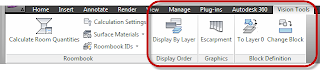
Display By Layer
The Display Order panel features one tool, Display By Layer, which runs the AecLayerOrder command.
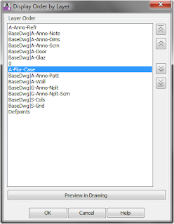
This tool allows you to rank the layers in a drawing and then have the display order set by the order in which the layers are ranked. This is a one-time deal. Future objects will appear on top of all previous objects; after setting the draw order by layer, that order is not dynamically applied to future objects. You can, of course, re-run the command, and the list is "remembered" with the drawing, so you do not need to recreate the list after saving, closing and then reopening the file. Note also that there is no way to "automatically clear" the draw order and return to what it was prior to applying this command. Two less-than-obvious ways this feature works involve external references. While you can re-order the layers of an external reference in the list and have it affect the display order, there are two limitations:
Escarpment
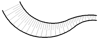
Use the Escarpment tool (AecEscarpment command) on the Graphics panel to create the linework often used to depict a sloping condition quickly and easily. You only need to pick the upper and lower sides and provide a distance between lines on the upper side. The generated linework is placed as a Block Reference, on the current layer; nested objects are on the current layer with ByBlock color, linetype, plotstyle (for drawings using named plot styles) and lineweight and ByLayer transparency and material.
To Layer 0
The To Layer 0 tool (AecMoveBlockToLayer0 command) on the Block Definition panel moves all nested objects within the Block Definition of a selected Block Reference to Layer 0. Unlike the Set Nested Objects to ByBlock option on the right-click menu when a block reference is selected (SetNestedObjectsByBlock command), this tool only changes the layer of the nested objects and leaves other attributes (color, linetype, plot style, and lineweight) alone. The SetNestedObjectsByBlock command also changes the color, linetype, plot style, and lineweight of the nested objects to ByBlock. The To Layer 0 tool also works on nested blocks, setting the objects within them to layer 0 as well; the SetNestedObjectsByBlock command does not affect objects within nested blocks.
Change Block
This tool runs the AecChangeBlock command, which allows you to select one or more Block References (which can have different Block Definitions) in the drawing and specify another Block Definition in the drawing for them. Insertion point, scale factors, layer, color, etc. remain unchanged. You have to type in the name of the new Block Definition. The command does offer a "?" option, which will list all of the Block Definitions in the drawing on the command line, for your reference.

Display By Layer
The Display Order panel features one tool, Display By Layer, which runs the AecLayerOrder command.

This tool allows you to rank the layers in a drawing and then have the display order set by the order in which the layers are ranked. This is a one-time deal. Future objects will appear on top of all previous objects; after setting the draw order by layer, that order is not dynamically applied to future objects. You can, of course, re-run the command, and the list is "remembered" with the drawing, so you do not need to recreate the list after saving, closing and then reopening the file. Note also that there is no way to "automatically clear" the draw order and return to what it was prior to applying this command. Two less-than-obvious ways this feature works involve external references. While you can re-order the layers of an external reference in the list and have it affect the display order, there are two limitations:
- Even though you can intermingle layers from an external reference with those of the host drawing and those of other external references, the net effect is to re-order the display of objects within the external reference relative to one another. All of the objects within a given external reference then are drawn relative to other objects based on the layer on which the external reference is inserted. For example, in the dialog above, even though the host layer A -Flor-Case appears in the list above the externally referenced layer BaseDwg|A-Wall, because the BaseDwg external reference is inserted on layer A-Anno-Refr (at the top of the list), all objects in the BaseDwg external reference will appear above objects on A-Flor-Case (or any other host drawing layer other than A-Anno-Refr).
- After saving a file with external references to which Display By Layer has been applied and then closing it, when you re-open the file, the display order applied to the layers in the externally referenced files is not automatically applied. The Layer Order list is remembered, however, so you can re-run the command to get the externally referenced layers order back to the way it was prior to saving/closing the file.
Escarpment

Use the Escarpment tool (AecEscarpment command) on the Graphics panel to create the linework often used to depict a sloping condition quickly and easily. You only need to pick the upper and lower sides and provide a distance between lines on the upper side. The generated linework is placed as a Block Reference, on the current layer; nested objects are on the current layer with ByBlock color, linetype, plotstyle (for drawings using named plot styles) and lineweight and ByLayer transparency and material.
To Layer 0
The To Layer 0 tool (AecMoveBlockToLayer0 command) on the Block Definition panel moves all nested objects within the Block Definition of a selected Block Reference to Layer 0. Unlike the Set Nested Objects to ByBlock option on the right-click menu when a block reference is selected (SetNestedObjectsByBlock command), this tool only changes the layer of the nested objects and leaves other attributes (color, linetype, plot style, and lineweight) alone. The SetNestedObjectsByBlock command also changes the color, linetype, plot style, and lineweight of the nested objects to ByBlock. The To Layer 0 tool also works on nested blocks, setting the objects within them to layer 0 as well; the SetNestedObjectsByBlock command does not affect objects within nested blocks.
Change Block
This tool runs the AecChangeBlock command, which allows you to select one or more Block References (which can have different Block Definitions) in the drawing and specify another Block Definition in the drawing for them. Insertion point, scale factors, layer, color, etc. remain unchanged. You have to type in the name of the new Block Definition. The command does offer a "?" option, which will list all of the Block Definitions in the drawing on the command line, for your reference.
April 10, 2013
ACA 2014: Door and Window Placement
Your requests have been heard. Prior to the 2011 release, when placing Doors and Windows, you had a choice between Unconstrained and Offset/Center, where the latter would center the Door or Window on a Wall segment if you click near the midpoint of that Wall segment or would offset the opening a user-set distance from the end of the Wall segment when clicking near that end. The 2011 release introduced a number of additional placement options, but in order to offer these, the Offset/Center option was split into two separate choices, Offset and Center. (Read more about this change in the 2011 release in a four-part series of posts starting here.) Many missed the convenience of having Offset/Center as a single choice and complained about lost efficiency in placing Doors and Windows. The 2014 release brings back the combined Offset/Center option

while keeping the options added in the 2011 release, as seen below on the Wall contextual ribbon tab, on the General panel.

In addition to restoring the combined Offset/Center option, you also now have options prior to placement for the justification of a Door or Window within the width of the Wall: in addition to the previous default initial justification of Center, you can now choose from Left and Right.

Where the Window is placed for Left or Right justification is determined the same way that Left and Right justification are determined for the Wall itself. Looking from the starting point of the Wall toward the end point, Left justification is to the left side of the Wall and Right justification is to the right side of the Wall.

If neither of these features gets your Door or Window placed exactly where you want it, the Reposition Along Wall and Reposition Within Wall tools are still available on the Door or Window contextual ribbon tabs or right-click menus, as well as the grip editing options.

while keeping the options added in the 2011 release, as seen below on the Wall contextual ribbon tab, on the General panel.

In addition to restoring the combined Offset/Center option, you also now have options prior to placement for the justification of a Door or Window within the width of the Wall: in addition to the previous default initial justification of Center, you can now choose from Left and Right.

Where the Window is placed for Left or Right justification is determined the same way that Left and Right justification are determined for the Wall itself. Looking from the starting point of the Wall toward the end point, Left justification is to the left side of the Wall and Right justification is to the right side of the Wall.

If neither of these features gets your Door or Window placed exactly where you want it, the Reposition Along Wall and Reposition Within Wall tools are still available on the Door or Window contextual ribbon tabs or right-click menus, as well as the grip editing options.
Subscribe to:
Posts (Atom)