January 06, 2015

Dyanmo: Custom Node, Integer To String - Zero Padding

Having created a node that would convert an integer to a string, padding a single-character string to two characters by adding an initial "0" so that a YYYYMMDD date string could be generated, it occurred to me that having a more general purpose node, where you could specify the number of characters to which the string should be zero-padded, would be more useful. As with the two-character node, no effort is made to truncate the original string if it exceeds the specified length, but strings with fewer characters will have the necessary number of zero characters ("0") added to the front of the string to bring it up to the specified number of characters.

As seen in the short Screencast below, the custom node takes two numeric inputs, the number of characters to which zero-padding is to be applied and an "integer" [see note at end of article] that is to be converted to a string, with zero-padding as necessary. In the Dynamo file I set up to demonstrate the custom node, an Integer Slider node (in the Library, Core > Input > Integer Slider) is used to specify the number of digits desired and a Number node (Core > Input > Number) is used to provide the integer to be converted to a string. Note that the Run Automatically toggle is checked, so as changes are made, the results are calculated and displayed without having to press the Run button each time.

Integer To String - Zero Padding Node
The image above shows the graph of the Integer To String - Zero Padding custom node. A description of the graph function follows.
  1. The integer to be converted to a string is processed by the Math.Floor node (Core > Math > Actions > Floor) to remove any fractional part (see note below) prior to being passed to the ToString node (Builtin Function > ToString), which converts it to a string.
  2. The integer string created in Step 1 is passed to a String.Length node (Core > String > Actions > Length), which returns the string length as an integer. A custom node called Zero Padding String takes the Final String Length as input to the Integer To String - Zero Padding custom node, and the string length of the integer string and returns a string containing the zeros that need to be added to the front of the integer string (if any). See below for the graph of this custom node.
  3. The zeros string from Step 2 is concatenated onto the front of the integer string from Step 1 by a String.Concat node (Core > String > Actions > Concat), which is then passed as the output of the Integer To String - Zero Padding custom node. Note that if the length of the Step 1 integer string is greater than or equal to the Final String Length, the zero string will be an empty string, and the end result will be equivalent to the Step 1 integer string.

Zero Padding String Node
The image above shows the graph of the Zero Padding String custom node. A description of the graph function follows.
  1. The easiest way to explain how this graph functions is to start with the LoopWhile node (Builtin Functions > LoopWhile). The LoopWhile node takes three inputs: init, the intial state of the object being processed; continueWhile, the test condition that determines whether or not the current object being processed should be processed again; and loopBody, which defines what action(s) are taken on each pass of the loop.
  2. The init input is provided by a Code Block node (Core > Input > Code Block; or double-click in the graph canvas). Code Blocks allow for custom scripting in Dynamo; in this case, it is being used to simply generate an empty string. A String node (Core > Input > String), with the input left blank, could also have been used; I felt that seeing the two double quotation mark characters, with no other characters in between, in the Code Block made the node read better. I also double-clicked on the Code Block title and renamed it to "Empty String" to more clearly indicate its purpose.
  3. The continueWhile input is the most complicated. A - [Subtraction] node (Operators > -) calculates the difference between the Final String Length input and the Starting String Length. If this is a positive number, it represents the number of zero characters needed in the final padding string. We want to compare the length of the current string to this number, and continue to process the string if the current string length is less than the desired string length. This comparison is done by the < [Less Than] node (Operators > <), and the current string length is generated by the String.Length node. For reasons beyond my current understanding, the output of the String.Length node cannot simply be put into the x input of the < node, and the result of that fed to the continueWhile input. The continueWhile input requires a single function as the input, and so a Function.Compose node (Core > Evaluate > Function.Compose) is used to combine these nodes in a way that is acceptable as input for the continueWhile input. The + and - buttons on the node allow you to add or remove function inputs so that you have the correct amount for your application. In this case, the initial default of two inputs was what was needed.
    You may have noticed that both the < and String.Length nodes have unconnected inputs. The LoopWhile node presumes that you will be doing something to whatever is passed to the init input, in this case, a string, and will supply that value to any open input of matching type. Likewise, the Function.Compose node supplies the integer value passed to the func0 input by the String.Length node to the open x input of the < node. Also note that by including the current value of the processed object in the evaluation, we make it possible for the the comparison to eventually be false, and for the loop to terminate. Failure to do so would result in an infinite loop, which is not a good thing.
  4. The loopBody input is fairly straightforward. Another Code Block node, renamed to "Zero String" creates a string with a single zero character in it. This is the input to the string0 input of a String.Concat node. The string1 input is left open, so the processed object string will be supplied here. Each time the loop body is entered, a zero character will be added to the front of the current processed object string, making it one character larger. Eventually, the processed string length will be equal to the difference between the Final String Length and the Starting String Length, the loop will terminate and the final result will be a string with the proper number of zero characters.
  5. To summarize, the loop starts with an initial value of an empty string. The length of that empty string (0) is compared to the difference between the Final String Length and Starting String Length inputs, to see if it is less than the difference. If that difference is 0 or a negative number, then the value fed to the continueWhile input is false, no action will be taken, and the result of the custom node will be an empty string. If the difference is 1 or greater, then the value fed to the continueWhile input is true, and the loop body code will be run, adding a zero character to the empty string. The loop process is then run again, but this time the current value is not an empty string but "0", and the string length is 1. If the difference is 1, then the less than condition is false and the "0" string is passed to the output of the custom node. Otherwise, the loop body is run again and "00" becomes the new current value of the string. This continues until the string length is not less than the difference, at which point the loop terminates and the current string value becomes the custom node result.


NOTE: I put "integer" in quotation marks when describing the node input above because while that is the intended input, both inputs will accept a double (precision real number), with a non-zero fractional value, as input. For the number to be converted, any fractional part is discarded prior to the conversion to a string. The way the Final String Length value is used, any fractional amount will be the same as specifying the next higher integer. If a given application could generate a value with a fractional amount as the input for the Final String Length and only the whole number value is desired, the Math.Floor node should be used to strip the fractional amount. This works for non-negative numbers; the function returns the first integer that is lower than the input value. For negative numbers, this will change the units number. So 1.9 becomes 1, but -1.1 becomes -2. I was not expecting to be using zero-padding on negative numbers; if you have an application that would require that, then you may want to modify the code to accommodate that. Note also that the sign ("-") counts as a character after a negative number is converted to a string. If you want the zero padding of a negative number to be calculated without including the "-" sign in the number of characters, the code would have to be modified to account for that.

January 05, 2015

ACA: AEC Modify Tools, Part 5, AEC Obscure

First post in series [AecLineworkExtend].
Previous post in series [AECLineworkSubtract].

The AecLineworkObscure command can be found on the Home ribbon tab, on the Modify panel flyout, by selecting the Obscure tool from the Obscure/Crop flyout. If the Obscure tool is not the displayed tool on the Obscure/Crop flyout, select the right side of the split button (down arrow icon) to deploy the flyout and choose the Obscure tool. Or, with no command active, you can right click in the drawing window, and choose AEC Modify Tools > Obscure from the context menu.

The AecLineworkObscure command is used to change the parts of linework, AEC Polygons, Mass Element Extrusions that have an embedded profile, Spaces and Hatches as well as Block References which contain any of these objects that fall within a user-defined obscuration area, replacing the linework or boundaries of the other items with linework placed on the layer defined by the HIDDEN Layer Key in the current Layer Key Style. This layer typically has a dashed linetype assigned. In the out-of-the-box Imperial content, using the AEC Title Case - NCS 256 Color Layer Key Style, this layer is G-Detl-Hidd, color Red and linetype HIDDEN2.

As with the AecLineworkSubtract command, there are two options for specifying the extents of the obscuration area:
  • Select one or more items in the drawing, which form at least one closed loop. Any single closed item will work (closed Polyline, Circle, Ellipse, AEC Polygon, Mass Element or Space), as will any combination of objects that, combined, form at least one closed loop.
  • Press the ENTER key when prompted to select items to be obscured, and then define an obscuration rectangle by selecting opposite corners of a rectangle. The rectangle will have sides parallel to the X- and Y-axes of the current UCS.
The primary use of this command is to make it easy to show parts of Detail Components that, for the detail at hand, occur behind another item, with a hidden linetype, without having to explode or manually break linework. It will work on linework and block references generated by other means.
Here are some additional notes regarding the AecLineworkObscure command:
  • MText, Text, Ellipses and Ellipse Arcs cannot be added to the selection set of objects to be obscured.
  • Ellipses and Ellipse Arcs can be selected as (part of) a boundary defining the area to be obscured.
  • Mass Elements with a shape other than "Extrusion" and Mass Element Extrusions that have an external Profile can be selected as objects to be obscured, but will not affected by the AecLineworkObscure command. These types of Mass Elements can be used to define the area to be obscured.
  • If a Block Reference is selected as an object to be obscured, only those nested objects within the block on which the AecLineworkObscure command works will be affected.
  • Attributes within a Block Reference will not be affected by the AecLineworkObscure command.
  • If a Block Reference is selected as an object to be obscured, it has obuscurable nested elements and it is the only instance of that Block Reference in the drawing, then the original block definition will be redefined to include the effects of the obscuration. If at least one instance of the Block Reference remains unaffected by the obscuration, then the original block definition will remain unchanged and the affected instance(s) will become instance(s) of new, anonymous block definition(s).
  • Multi-View Blocks can be selected as an object to have a part obscured, but will not be affected by the command.
  • If the active View Block of a Multi-View Block contains linework that forms a closed boundary or contributes to a closed boundary, it can used to define the area to be obscured.
  • Unlike the AecLineworkTrim, AecLineworkDivide and AecLineworkSubtract commands, use of the AecLineworkObscure command on a closed Polyline or Circle does not result in one or more closed Polylines.
  • A Line or Arc, freestanding or within a block reference, that is in the selection set of the AecLineworkObscure command is replaced with one or more Polylines.
  • A Circle, freestanding or within a block reference, that is in the selection set of the AecLineworkObscure command is replaced with one or more Polylines for the portion(s) outside of the area being obscured and one or more Arcs for the portion(s) within the area being obscured. The Polyline(s) and/or Arcs will have vertices/endpoints at the World Coordinate System 0-degree and 180-degree locations on the original Circle.
  • A closed Polyline, freestanding or within a block reference, that is in the selection set of the AecLineworkObscure command is replaced with one or more Polylines for the portion(s) outside of the area being obscured and Lines/Arcs for the portion(s) within the area being obscured.
  • An open Polyline, freestanding or within a block reference, that is in the selection set of the AecLineworkObscure command is replaced with one or more Polylines for all portions, whether within or outside of the area being obscured.
  • If a hatch object is to be obscured, the hatch will be removed from the from the obscuration area, but no hidden graphics will be generated.
  • Obscuring an associative Hatch will result in a non-associative Hatch, regardless of whether or not the boundary of the Hatch is included in the obscuration.
  • Associative Spaces, Walls, Doors, Windows and Door/Window Assemblies can be selected as items to be obscured, but will not be affected by the command. Non-associative Spaces do work with the AecLineworkObscure command.
  • If you obscure an AEC Polygon, the Exterior Edge components of the AEC Polygon that fall with in the obscuration area will be replaced with "hidden" lines or arcs. Interior Edge components of the AEC Polygon, if present, are removed, but not replaced with "hidden" linework. New Exterior Edges and, if present, Interior Edges are created when the AEC Polygon extends beyond the obscuration area, but these new edges are "invisible" - no linework is drawn on screen. If Interior or Exterior Hatch or Fill components are turned on, they will, however, change to fill in the modified AEC Polygon extents, which does not give a true obscuration effect.
  • If the area to be obscured effectively splits an object into two or more separate pieces, the result depends upon the selected object. Hatches, Mass Element Extrusions (embedded Profiles), AEC Polygons and Spaces will result in one object, with two (or more) separate, non-contiguous regions. See above for note on how new AEC Polygon Edges will not have any visible graphics.
  • If an object (or nested object, in the case of a block reference) in the obscure selection set is entirely within the obscuration boundary, it will be completely replaced with hidden linework.
  • Unlike the AecLineworkSubtract command, if you select one or more objects to define the extents to be obscured, you are not prompted as to whether the boundary objects are to be erased.
  • Even though Mass Element Extrusions (with embedded profile) are 3D objects and Spaces can be 3D objects, the hidden linework is only 2D, in the current X-Y plane. The removal of portion of these objects in the obscuration area does affect the object in 3D.

As with the AecLineworkDivide and AecLineworkSubtract commands, there are object types and combinations of objects within a Block Reference that I did not test. If you are thinking of using the AecLineworkObscure command in a situation that you have not previously encountered, you may want to use the Mark option of the UNDO command to place one or more UNDO Marks prior to using the command, so that you can easily UNDO Back to the point before the command was used if you get unexpected results.

Next post in series [AECLineworkMerge]

January 03, 2015

Autodesk Application Manager - Update README

Perhaps unlike many, I prefer to look through the README that generally accompanies updates to the Autodesk products I use. These are usually available from a link on the same webpage from which the update is downloaded. With the introduction of the Autodesk® Application Manager, access to updates is made easier (at least for an individual user) and often earlier than on the Autodesk website. I was initially disappointed that there was not a link to the README available in the Application Manager. It turns out I just did not know where to look (and the fact that the link to the README does not include "README" in the link label made it somewhat less discoverable). This brief Screencast shows how to expose the "Details" (a brief description) of an update, as well as the View Details link to the README.


My other reservation was not having the update file for later use, if necessary. Those do get downloaded and saved to your computer; you can find (and, if you like, customize) the location where the updates are saved by selecting the Settings tool in the upper right corner of the Application Manager, and then selecting the Files tab. The Local Files Location specifies where the folder under which updates are stored. Look at the edit box to see the current location or click on the ellipsis (...) button to open a dialog to see the current location and, if desired, navigate to a new one.

December 27, 2014

Dynamo - Custom Node, 2 Char Zero Padding

Dynamo provides a way to modularize code, both to make it easy to reuse in future projects and to make it easier to follow the flow in the main routine. Creating a custom node is as easy as selecting the group of nodes that perform a particular function in a Dynamo file and choosing Edit > Create Node From Selection from the pull-down menus or pressing CTRL+D.

The image above shows the Coded Date Parameter graph with the custom nodes replaced with the underlying nodes. This works, but it occurred to me that I might want to reuse the conversion of an integer to a two-character, zero-padded string part in the future, By creating a custom node for that part of the graph, I can save the custom node (as a DYF file) to my Dynamo definitions folder, where it will be available in the left-sash Library. An added benefit is the simplification of the main graph.

Creating a Custom Node
  1. Select the nodes to be included in the custom node. Multiple nodes can be selected by holding down the SHIFT key as you select individual nodes or by clicking in an empty space in the graph and, while holding the left mouse button down, dragging to enclose the nodes within a window. Like AutoCAD, if your second drag point is to the right of the first, you will have a window selection that only selects nodes completely within the window; if your second drag point is to the left of the first, you will have a crossing window that will select nodes that are either completely or partially within the window.
  2. Select Edit > Create Node From Selection or press CTRL+D.
  3. In the Custom Node Properties dialog, enter a Name and a Description (tooltip) for your custom node. Then specify a Category, which determines where the node will appear in the Library. NOTE: You do not have to select from the existing categories; you can type in a category of your choosing. Use a period to separate the name of an upper level category from the name of a nested category. In the example shown, I created a new top level category for my own nodes called "DWK" (my initials) and a subcategory called "String" below that. Press OK to create the custom node.
  4. Observe that the selected nodes have been replaced by a custom node, and that a new tab has appeared in the workspace.
  5. Select the Integer to String - 2 Char Zero Padding tab to make it current, and then, in the upper right corner of the graph pane, select the top icon (dashed line square) to zoom to the extents of the graph.
    Notice that Dynamo added Input and Output nodes to the custom node graph, one Input for each "wire" leading into the selected nodes and one Output for each "wire" leading out of the selected nodes. These represent the inputs and outputs of the custom node. You can rename the labels (object and result in this example in the image above) that appear on the custom node by selecting the label and typing the desired name. I chose to rename the input label to integer and the output node to string.
  6. Assuming that your original graph worked, the custom node is now complete. All that remains is to save the node to a DYF file, in your Dynamo definitions folder. Select File > Save from the pull-down menus or press CTRL+S to save the file. The Save As dialog should default to the appropriate folder (in my case, C:\Users\dkoch\AppData\Roaming\Dynamo\0.7\definitions; substitute your user name and Dynamo version). Failure to save the file will likely result in an undefined node in the DYN file from which you created the custom node. If you try to close the custom node tab without saving, you will be alerted to the fact that there are unsaved changes.
Integer To String - 2 Char Zero Padding Node
This custom node expects to receive an integer input, and uses the ToString node (Core > Builtin Functions > ToString) to convert the integer to a string. This string is then sent to three different nodes:
  • A String.Length node (Core > String > Actions > Length) determines the number of characters in the string. A Number node (Core > Input > Number), set to 1.000, is compared to the string length by a != [Not Equal] node (Operators > !=), which will return true if the string length is anything but 1 and false if the string length is one.
  • A String.Concat node (Core > String > Actions > Concat) concatenates the outputs of a String node (Core > Input > String), set to "0", and the output of the ToString node. This creates the potential zero-padded condition.
  • An If node (Core > Logic > If) also receives the output of the ToString node, in its true input. The If node is used to determine what string will become the output of the custom node. If the result of the != node, which is fed to the test input of the If node, is true (string is not one character in length), then the original string from the ToString node is passed through as the result, since it is the input for the true input of the If node. If the original string is one character in length, then false will be passed to the test input of the If node, and the results of the String.Concat node, which is passes to the false input of the If node, will be passed through.
The net result is that if a single-digit integer is the input of the node, it will be converted to a string and have a single zero character added at the front of the string. Any other length string will be passed through "as is." Since the input to this custom node is an integer representing a month or a day, the input will only have one or two digits, and this node will provide the desired zero-padding to yield a two-character string in all cases. Any future reuse of this node would require the main graph to assure that the integer input would be in the range of 0 to 99 for a two-character result.

After getting this to work, it occurred to me that it would be more useful to have a custom node that could handle zero-padding to any specified number of characters. But since this node satisfied the needs of the immediate task, I chose to save creating such a custom node as a future task.

December 23, 2014

Dynamo - Custom Plot Stamp

Here is an example of using Dynamo to do two things that you cannot do natively in Revit®: convert one data type to another (in this example, converting integers to strings) and concatenating multiple strings into one string. The inspiration for creating this Dynamo file was this thread in the Autodesk Revit Architecture Discussion Group. The request was a wish for the ability to created a customized date stamp, showing just a numeric date in yyyymmdd format, with three "random" numerals in front and in back, to "disguise" the actual purpose of the string, while allowing those who know to see when the plot was made. The comparison was to what you can do with Fields in AutoCAD®. While the Dynamo file, by its very nature, cannot provide the automatic update that AutoCAD Fields provide, it can standardize the formatting of the custom date stamp, and make manual updates easier than editing the value in the Project Properties dialog.

NOTE: If you work in a "shared" environment, please consult with your BIM Manager and/or co-workers before modifying an office- or project-standard shared parameters file, project template or title block family.

The first stage is to set things up in Revit. This is done the same way that you would do it to set up a manually updated title block parameter. A quick summary of that follows:
  1. Create a shared parameter to be used to hold the custom plot stamp text, if you do not already have one. On the Manage ribbon tab, on the Settings panel, select the Shared Parameters tool. Set the appropriate shared parameters file current, select the appropriate parameter group and create the parameter. Set the parameter type to Text and add a tooltip description (2015 release or later), so that others will know the purpose of the shared parameter.
  2. Add a Project Parameter to your project (for an existing project) or your project template(s) (for future projects). Choose the Shared parameter radio button and then choose the Select button to choose the shared parameter created in Step 1. Select a group under which the parameter will be placed, if the initial "Text" group is not to your liking. Choose the Instance radio button and set the Category to Project Information.
  3. Edit your title block family or families. In each one, add a Label to display the value of the shared parameter created in Step 1. On the Create tab, on the Text panel, choose the Label tool. In the Edit Label dialog, select the Add Parameter tool in the lower left, and add the shared parameter created in Step 1. Select the newly added Shared Parameter in the Category Parameters list box and select the Add parameter(s) to label tool (green arrow icon). Change the Sample Value for the parameter, if desired, then select OK. Fine tune the location and orientation of the label in your title block family, then save or save as the family, if desired, and load the title block family into your project and/or project template file.
At this point we have a Project Parameter that can be set in one place for the entire project, and which will display in the label added to the title block family(ies).
You could open the Project Properties dialog (Manage ribbon tab, Settings panel, Project Information tool) and manually enter a value (or select an instance of the title block and click on "?" for the label you added and type the value in there. While that is a perfectly valid workflow, by using Dynamo, you can update the value in a consistent manner. The image below shows the overall Dynamo graph, followed by an explanation of the parts.
  1. Three stages of nodes generate the pieces of the numeric date in yyyymmdd format. The DateTime.Now node (Library path = Core > DateTime > Now) generates the current system time and date. In the image below, all of the nodes have a "watch toggle" and they are toggled on, so that the value of the node is displayed below the node. We only need the year, month and day, so the value of that node is passed to the DateTime.Components node (Core > DateTime > Actions > Components), which generates separate numeric values for the listed components. The third stage consists of one ToString node (Core > Builtin Functions > ToString), which converts the numeric year output from the DateTime.Components node to a string (text), and two custom nodes named Integer To String - 2 Char Zero Padding, which convert the month and day output from integers to strings while also assuring a two-character result by adding a "0" at the front of any single-character strings. These custom nodes were created from a number of out-of-the-box nodes; I will discuss the creation of custom nodes and show the inner workings of these nodes in a future article.
  2. The random three-digit prefix and suffix are generated by two similar sets of nodes. In each, two Number nodes (Core > Input > Number) establish the range of double-precision real number values that the Math.Random node (Core > Math > Actions > Random(value1:double, value2:double)) uses when generating a double-precision random number. I chose 100 and 999 as the boundaries to assure I would get a three-digit (whole number part) result. Note that I had chosen three decimal place display for numbers in Dynamo at the time these screen captures were take, so all numeric values, even integers, display with three decimal places (Settings pulldown menu > Number Format > 0.000). The output of the Math.Random node is passed through the Math.Floor node (Core > Math > Actions > Floor), to convert the double to an integer (rounding down to the next integer value, effectively truncating any fractional amount), prior to using another ToString node to convert the integer to a text string.
  3. We now have all of the strings we need to create the text value for the plot stamp. A String.Concat node (Core > String > Actions > Concat) takes the five strings (random prefix, year, month, day and random suffix) and combines them into one string. The String.Concat node starts out with one input, string0; you can use the + button to add more inputs and the - button to remove inputs as required by your application.
  4. Now that we have the nodes required to generate the string we want for the plot stamp, we need to get that value out of Dynamo and into the DateCode parameter in Revit. To do that, we first need to get the ProjectInfo element, which holds the Project Information parameters. Two nodes will do that for us. First, the Categories node (Revit > Selection > Categories) allows you to select from a list of all of the built-in Revit categories, one of which is ProjectInformation. Passing that category to the All Elements of Category node (Revit > Selection > All Elements of Category) selects the ProjectInfo element for the current project. These two nodes do not have a "watch toggle", so I included a Watch node (Core > View > Watch) in the overall graph (not shown in the image below) to view the result of the All Elements of Category node. This is not needed for the Dynamo function to work.
  5. The Element.SetParameterByName node (Revit > Elements > Element > Actions > SetParameterByName) is where our value gets pushed into the Revit project. It takes three inputs, the element we acquired in Step 7, a string from a String node (Core > Input > String) into which the name of the parameter to be set has been entered (case sensitive, enter the name exactly as it appears in Revit), and the value to be set, which is the concatenated string from Step 6.
With all of the elements in place, and the graph saved to a Dynamo file (DYN extension), it is simply a matter of pressing the Run button to initiate the program. Dynamo will generate the prefix and suffix numbers, gather up the year, month and day numbers, convert them all to strings and combine them into one string. The Project Information element will be accessed and the string value will be used to set the value of the DateCode parameter.

This may seem like a lot of work, compared to typing fourteen numbers in a dialog box, and if you only ever use it one time, it is. But you can save the Dynamo file and every time you are about to plot, simply start Dynamo, open the file and select the Run button.

In this admittedly simple example, you can see how easy it is to write a program in Dynamo and have that program interact with Revit. Dynamo takes care of all of the hard work of interfacing with the API; all you need to do is connect the nodes.

December 19, 2014

Dynamo

I had the good fortune to be able to attend Autodesk University this year, and without initially intending to do so, ended up with the majority of my classes centered on Dynamo. Dynamo is an open-source add-in that works with Revit (and Vasari) and provides a graphical means of creating custom programming for Revit. The architect side of me appreciates the graphical interface; the long-time AutoCAD®/AutoCAD® Architecture customization side of me (AutoLISP®, VBScript in formula properties) appreciates the ability to do things and process data in ways not accommodated by the out-of-the-box commands and features.

I have had a long-time desire to become familiar with the Revit API and explore the possibilities available there, but a combination of a lack of significant stretches of dedicated time and being somewhat intimidated by the amount of things I would have to learn just to get started have conspired to keep me from starting that journey. From what I have seen so far of Dynamo, there is a much lower entry barrier, and I am excited to learn more and apply that knowledge to real-world, useful projects.

As I discover things (or have others show them to me), I expect I will be documenting them here. Until then, here are links to the Dynamo website and other related resources.

Dynanmo Website
Dynamo Downloads
Dynamo Tutorials
Dynamo Blog
Dynamo Gallery
Dynamo Community (discussion forum)

I would also like to express my thanks to Zach Kron, Marcello Sgambelluri, Nathan Miller, Ian Keough, Michael Hudson, Andrea Vannini and Nuri Miller, who taught one or more of the classes I took at Autodesk University this year. Check out the materials that are available on line:

AB6644: Dynamo: The Future is Wide Open - Zach Kron (session recorded)
AB6542: Explore the Possibilities with Computational BIM - Ian Keough (session recorded)
AB6557: Practically Dynamo: Practical Uses for Dynamo Within Revit - Marcello Sgambelluri (session recorded)
AB6545-L: Dynamo for Dummies: An Intro to Dynamo and How It Interacts with Revit - Marcello Sgambelluri
AB5482: The Great Dynamo Dig: Mine Your Revit Model with Computation - Nathan Miller (session recorded)
AB5492: White-Glove Packaging: Creating Custom Dynamo Nodes - Nathan Miller
AB6495: Dynamo Hero: Using Revit Scripting Tools to Optimize Real-World Projects - Michael Hudson and Andrea Vannini
SD5132-L: Automation Prototyping: A Side-by-Side Comparison of Dynamo and the Revit API - Nuri Miller

December 11, 2014

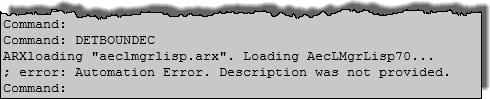
AutoCAD: Automation Error. Description was not provided.

While I am certain that the error message in the title above will be issued for any number of reasons, I came across this when some users were trying to run a custom AutoLISP® routine that draws an area to be enlarged "box". Until yesterday, I was unable to reproduce the issue on my own computer, making it hard to figure out what was causing the error. Having determined at least one cause for this error message, I decided to document it here.

Finally running into the error myself yesterday, I was able to use the VisualLisp IDE to step through the main routine and determine that the crash was occuring during a call to a subroutine that returns a list of the Layer Keys in the current Layer Key Style. While I would like to think of myself as a relatively competent AutoLISP programmer, there are definitely areas where my skills and experience are thin; error handling routines are one such area. At the time I wrote that subroutine, I was not aware that the out-of-the-box (AecLayerKeyList) function (defined in AecLMgrLISP.arx) would do what I wanted from my subroutine (I was likely confused by the description of the routine as returning "a resbuf list of strings"), so I wrote my own, with no error handling. It turns out that at some point in the past, our office standard Layer Key Style ended up with a corrupt Layer Key. Attempting to read the name of this layer key results in the "undescribed" error. Both the (AecLayerKeyList) function and the Style Manager are capable of handling the error. Style Manager just omits the corrupt Layer Key; the (AecLayerKeyList) function includes the name as an empty string (""), which is not valid input for the name of a Layer Key.

Overwriting the "bad" Layer Key Style with one that does not have the corrupt Layer Key resolves the error and allows the area-to-be-enlarged routine to run. That was much easier than adding error handling to my routine, and should probably be done in any event.

November 30, 2014

ACA: AEC Modify Tools, Part 4, AEC Subtract

First post in series [AecLineworkExtend].
Previous post in series [AECLineworkDivide].

The AecLineworkSubtract command is available on the Home ribbon tab, on the Modify panel flyout, by selecting the Subtract tool from the Merge/Subtract flyout. If the Subtract tool is not the displayed tool on the Merge/Subtract flyout, select the right side of the split button (down arrow icon) to deploy the flyout and choose the Subtract tool. Or, with no command active, you can right click in the drawing window, and choose AEC Modify Tools > Subtract from the context menu.

The AecLineworkSubtract command can be used to subtract (delete) parts of linework, AEC Polygons, Mass Element Extrusions that have an embedded profile, Spaces and Hatches as well as from Block References which contain any of these objects. There are two options for specifying the extents of the subtraction area:
  • Select one or more items in the drawing, which form at least one closed loop. Any single closed item will work (closed Polyline, Circle, Ellipse, AEC Polygon, Mass Element or Space), as will any combination of objects that, combined, form at least one closed loop.
  • Press the ENTER key when prompted to select items to subtract, and then define a subtraction rectangle by selecting opposite corners of a rectangle. The rectangle will have sides parallel to the X- and Y-axes of the current UCS.
If you select objects to specify the subtract border, you will asked if you want to erase the selected items. The default response is No. The Screencast embedded below shows the AecLineworkSubtract command in use on various object types. As with the AecLineworkTrim and AecLineworkDivide commands, if the original object was a closed object, a closed obejct will result, with Circles becoming closed Polylines.
Here are some additional notes regarding the AecLineworkSubtract command:
  • MText, Text, Ellipses and Ellipse Arcs cannot be added to the selection set of objects from which to subtract a portion.
  • Ellipses and Ellipse Arcs can be selected as (part of) a boundary defining the area to subtract.
  • Mass Elements with a shape other than "Extrusion" and Mass Element Extrusions that have an external Profile can be selected as objects from which to subtract, but will not affected by the AecLineworkSubtract command. These types of Mass Elements can be used to define the area to subtract.
  • If a Block Reference is selected as an object from which to subtract, only those nested objects within the block on which the AecLineworkSubtract command works will be affected.
  • Attributes within a Block Reference will not be affected by the AecLineworkSubtract command.
  • If a Block Reference is selected as an object from which to subtract, it has subtractable nested elements and it is the only instance of that Block Reference in the drawing, then the original block definition will be redefined to include the effects of the subtraction. If at least one instance of the Block Reference remains unaffected by the subtraction, then the original block definition will remain unchanged and the affected instance(s) will become instance(s) of new, anonymous block definition(s).
  • Multi-View Blocks can be selected as an object to have a part subtracted, but will not be affected by the command.
  • If the area to subtract effectively splits an object into two or more separate pieces, the result depends upon the selected object. Closed Polylines and Circles will result in two (or more) separate Closed Polylines. Hatches, Mass Element Extrusions (embedded Profiles), AEC Polygons and Spaces will result in one object, with two (or more) separate, non-contiguous regions.
  • Associative Spaces, Walls, Doors, Windows and Door/Window Assemblies can be selected as items from which to subtract, but will not be affected by the command. Non-associative Spaces do work with the AecLineworkSubtract command.
  • Subtracting from an associative Hatch will result in a non-associative Hatch, regardless of whether or not the boundary of the Hatch is included in the subtraction.
  • If an object in the subtract selection set is entirely within the subtraction boundary, it will be deleted.

As with the AecLineworkDivide command, there are object types and combinations of objects within a Block Reference that I did not test. If you are thinking of using the AecLineworkSubtract command in a situation that you have not done so previously, you may want to use the Mark option of the UNDO command to place one or more UNDO Marks prior to using the command, so that you can easily UNDO Back to the point before the command was used if you get unexpected results.

Next post in series [AECLineworkObscure].

November 23, 2014

ACA 2015: Cannot invoke (command) from *error* without...

Several people in the Autodesk AutoCAD® Architecture General Discussion Group have experienced problems when trying to run AutoLISP routines in which an error condition is encountered. Instead of the usual, often helpful, error message at the Command: line, this error shows up, instead:
Cannot invoke (command) from *error* without prior call to (*push-error-using-command*).

This appears to happen even when the first thing you do in a drawing is evaluate a LISP expression with an error, for example, by typing (alert 1) at the Command: prompt and then pressing ENTER.

If you were hoping for a more informative error message, so you could try to work out what went wrong, you will want to reset the initial definition of the *error* function to what it should be:
(defun *error* (msg) (princ "error: ") (princ msg) (princ))

One way to get this code loaded into every drawing you open would be to include it in your ACADDOC.lsp file (if you have one; if not, you can create one). This file needs to be somewhere in the AutoCAD Search path (and be the first on of that name found); if your firm has a standard ACADDOC.lsp file and you do not have rights to edit it, you may want to discuss having this code added to it with your CAD Manager. You will also want to have the folder in which the ACADDOC.lsp is placed be designated as a Trusted Path (Files tab of Options dialog) if you have SECURELOAD set to 1 to avoid the nag dialog about loading it. If SECURELOAD is set to 2, you have to have the ACADDOC.lsp file in a Trusted Path folder, or the file will not load at all.

There are other ways to get this code loaded with each file, if using ACADDOC.lsp does not work for your situation. The easiest would be to open Notepad and paste the code above into it, then save the file with a name of your choosing and a LSP extension, again, to a folder that has been designated as a Trusted Path. Then add that file to your Startup Suite in the Load/Unload Applications dialog (APPLOAD command).

I am not sure why the *error* function is not properly initialized, but running the above code when opening a drawing or creating a new drawing will resolve this issue and give you the expected error messages.

November 09, 2014

ACA: AEC Modify Tools, Part 3, AEC Divide

First post in series [AecLineworkExtend].
Previous post in series [AecLineworkTrim].

I decided not to wait six years between posts on the AEC Modify tools this time. Today's featured command is the AecLineworkDivide command. This command can be accessed on the Home ribbon tab, on the Modify panel flyout or from the right-click context menu (no command active), by choosing AEC Modify Tools > Divide.

The Screencast embedded below shows the AecLineworkDivide command in action. As shown in the Screencast, the command works on linework, Mass Element Extrusions that have an embedded profile, AEC Polygons, Spaces and Block References that contain at least one of the previously mentioned objects. 11/23/2014 Update: "Linework" includes Hatches.

You can specify the dividing line in two ways (just as you could do so for the AecLineworkExtend and AecLineworkTrim commands), either by selecting two points, as was done in the Screencast, or, by pressing the ENTER key when prompted for the first point, and then hovering over an existing line in the file and left clicking when the desired dividing line is highlighted. No matter which method you choose, the dividing line is treated as being infinite in length; the endpoints need not be outside the extents of the selection set.

When a closed item is divided by the AecLineworkDivide command, the resulting objects are also closed, whether the objects are main objects or nested within a Block Reference. A divided circle results in two closed Polylines. A closed Polyline results in (at least) two closed Polylines. An open Polyline results in at least two polylines, and possibly many more, if the dividing line crosses the Polyline multiple times, as it does in the example in the Screencast.

Here are some additional things of which to be aware when using the AecLineworkDivide command:
  • MText, Text, Ellipses and Ellipse Arcs are not dividable and cannot be added to the selection set for the AecLineworkDivide command.
  • Mass Elements with a shape other than "Extrusion" and Mass Element Extrusions that have an external Profile assigned are not dividable. If you include these types of Mass Elements in the selection set of the AecLineworkDivide command, the entire object will be duplicated, even if the dividing line does not intersect the Mass Element.
  • If you divide a Block Reference with dividable nested objects that has just one instance in the file, then the original block definition will be redefined as the objects on one side, and an anonymous block will be created for the objects on the other side. If there are other instances of a Block Reference that are not in the selection set, then the original definition will be left as is, and anonymous block definitions will be created for both sides of the divided Block Reference.
  • When undividable items are present in a block reference that is being divided, the undividable elements will be included in the block definition of both of the newly created blocks.
  • Weird things happen when you divide an attributed block. If there are no dividable objects, the attributed block may be "replaced" with an anonymous block, which may not be annotative even if the original block was. If there are dividable items in the attributed block, then you will likely get two blocks, with the attributes in both, although in my tests the actual instance in the file of one of the blocks did not have the attributes, but inserting another instance of it did result in attributes.
  • Multi-View Blocks are selectable, but will not actually divide, even if the underlying view block contains dividable graphics. The Multi-View Block will duplicate, however (in place), even if it is not cut by the dividing line. This is actually quite handy in the case of a Multi-View Block Space tag, where you are dividing the Space as well. If you include both the Space and the Tag in the same AecLineworkDivide command selection set, then each of the two Spaces created by the divide will be tagged by one of the two Tags generated. You will still have to manually separate the two Tags.
  • In some cases where the object to be divided is irregularly shaped, the divide may create more than two potential objects, for example, a U-shaped closed Polyline or Space divided across the arms of the "U". For the Polyline, you will get three closed Polylines. For the Space, you will only get two Spaces, one of which will have two non-contiguous sub-areas.
  • Walls, Doors, Windows and Door/Window Assemblies do not work well with the AecLineworkDivide command. These items will not be split (not even Walls), but they will duplicate in place, creating, in the case of Walls, cleanup nightmares, and duplicate objects in the other cases. I would not recommend including these items in the selection set of the AecLineworkDivide command.
  • Associative Spaces are also not good candidates for the AecLineworkDivide command. The entire Space will be duplicated, and both will be associative to the same boundaries. I cannot think of a scenario where that would be the desired end result. Non-associative Spaces work just fine, as seen in the Screencast.
  • 11/23/2014 Update: If you select the boundary of an associative Hatch, select the Hatch as well, if you want the Hatch to remain associative and to be associative to the trimmed boundary. Otherwise, the Hatch will become non-associative and retain its extents.

I am sure I have missed some object types or some combination of objects nested inside a Block Reference that have unexpected results when the AecLineworkDivide command is applied. I suggest using the Mark option of the UNDO command to set one or more UNDO Marks prior to using the AecLineworkDivide command in unfamiliar situations, so that you can easily UNDO Back to the Mark if things are not to your liking. That said, there are cases where this command can be handy, when used appropriately.

Next post in the series [AECLineworkSubtract].