Long-time readers (both of you) may recall this post from nearly two years ago. It contains a link to a page on the Autodesk website from which you could download a utility program (tableprint8.exe) that would export the content of a Plot Style file (STB or CTB) to a comma-delimited text file, suitable for printing or opening with a spreadsheet program such as Excel. For those who prefer the challenge of finding that page from the Autodesk home page, you can start there, then click on each of the following links to hop from one page to the next to get there: Home > Building > Products & Services > Autodesk® Architectural Desktop > Training > How-to Articles > Routines, Tools and Add-ons > Plot Tool: CTB and STB Printing.
If you use one of the 2004-format versions of ADT (2004, 2005 or 2006), that is the file you want, and if you have not already downloaded it, you may want to do so soon, as there is not telling when the version on that page will be replaced with the current, 2007 version, tableprint9.exe. If you are already using ADT 2007 (or any other AutoCAD-2007-based product, you can grab tableprint9.exe on this page. For those who like to navigate on the Autodesk site, you can start at the home page and follow these links: Home > Building > Products & Services > Autodesk® Architectural Desktop > Data & Downloads > Utilities & Drivers > CTB and STB Printing Tool for AutoCAD 2007 under the Autodesk® Architectural Desktop 2007 section.
Whichever version you use, be certain to read and follow the installation instructions. The EXE file will need to be copied to the same folder as the acad.exe file.
There are a lot of other interesting items on the intermediate pages, so while clicking on the direct link here will speed you on your way, you may want to explore the other items available when you have a spare moment or two.
January 02, 2007


December 27, 2006
Wall Corner Condition - Plan Modifiers
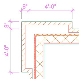
With some additional help from John Mumaw in a follow up reply to the Wall Corner Condition thread in the Autodesk Architectural Desktop Discussion Group, I was able to get wall modifiers to work in creating a projecting brick pier at an outside corner intersection of two walls. See this post for a description of another way to do it with Wall Endcaps. The image above shows the desired end result.
Here are some tips for using plan modifiers for achieving the results above. Credit goes to Mr. Mumaw for most of what follows.
- You will need to draw your walls so that the graph lines extend past their intersecting point, then use a cleaup radius to get the walls to clean up.
- Do not make the modifiers the exact size you need, as that results in the "interesting" results shown below. Notice the "leaking" brick hatch and extra Shrink Wrap/Component line.
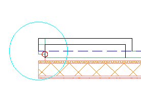
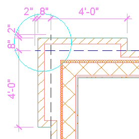
- Instead, make the modifiers some distance longer that you need. You will then need to draw the walls that same extra distance beyond the projection, and the wall cleanup will take care of the "extra" length. I chose to use 2". The image below shows the two polylines I used to create the plan modifiers. Note that the modifiers have not yet been applied to the wall shown in this image, which was drawn from left to right, so the modifiers are at the start of this wall. The brick polyline starts at the outer face of brick, offsets up 8", runs 2" longer than the desired pier length, for a total of 4'-10" and runs back 8" to the brick face. The air gap polyline is offset 4" from the brick polyline, so that the 4" width of the brick is maintained and the start and stop points are at the outer face of the air gap component.
- If you apply the modifiers to a stand-alone wall, a cleanup error will result. This is not a cause for alarm, as this technique only works when the wall cleans up with another wall.
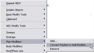
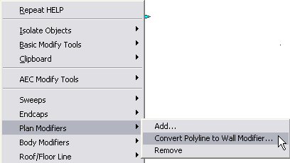
- To create the plan modifier from the drawn polyline, select the wall along which you drew the polylines, right click and choose Plan Modifiers > Convert Polyline to Wall Modifier... from the context menu.
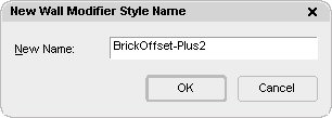
Choose whether or not you want to save the polyline, then give the modifier a meaninful name.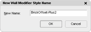
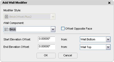
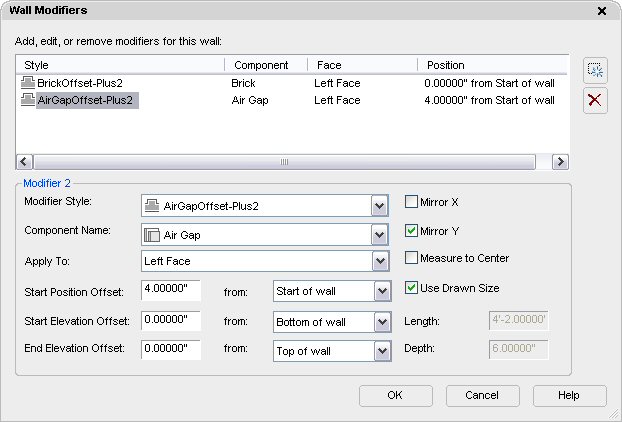
Verify that the correct component is indicated in the Add Wall Modifier dialog, and make certain that the Offset Opposite Face toggle is NOT checked. - The plan modifiers will be attached to the wall you selected. If this wall will be used as one of your corner walls, select the wall, right click and choose Properties. On the Design tab, in the Advanced category and Worksheets subcategory, click on the Plan Modifiers worksheet and check the settings for your modifiers. If your wall style is created like the out-of-the-box wall styles, with the first component at the outside component and the last component to the inside, then you will want the modifiers to be attached to the left face of your components, with the Mirror X and Measure to Center toggles unchecked and the Mirror Y and Use Drawn Size toggles checked. The Start Position Offset for the Brick component should be 0 from the start of wall; the Start Position Offset for the Air Gap component should be the width of the brick component from the start of wall, 4" in this case. If you drew your polylines at the end of a wall, rather than the start, the Air Gap Offset would be -4" from the end of wall.
- If your pier is symetrical, you can use the same plan modifiers for the other wall. Make note of what end of the wall you need the modifiers, start or end. Then select the wall, right click, choose Properties and open the Plan Modifiers Worksheet. Add the modifiers already created by choosing the appropriate name and component, then making certain to check the toggles as noted above. Use a positive offset for the Air Gap component when placing the modifier at the start of wall and a negative offset when placing the modifier at the end of wall.
- The image below shows two left justified walls. The vertical wall was drawn from bottom to top and the horizontal wall was drawn from left to right. The wall modifiers shown above have been added to the end of the vertical wall and the start of the horizontal wall. The Graph Display Representation is toggled on so you can see that the graph lines of the two walls were extended 10 total inches beyond their intersecting point, 8" for the brick offset plus 2" for the extra length at which the plan modifiers were drawn. A cleanup radius of 1'-6" was added to each wall at the intersection end so that the walls would clean up with each other, giving the desired result. The minimum cleanup radius here would be 10 times the square root of 2 inches, which you could get by using the grip to stretch each radius to the endpoint of the other wall's graphline.
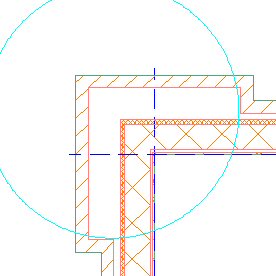
- You can use other justifications besides left, but you will need to increase the cleanup radius accordingly. Keep in mind that the larger the cleanup radius, the greater the chance that there will be a problem with other walls close to the corner. The images below show baseline and right justified walls using the same modifiers, but with larger cleanup radii to compensate for the greater distance between the graphline endpoints. Note also that the graphline endpoints remain 10" beyond the outer face of the wall.





December 16, 2006
Wall Corner Condition
I was reading a thread titled Wall Corner Condition in the Autodesk Architectural Desktop Discussion Group in which "adtcad" posted an image of a multi-component wall where the brick offset at an outside corner on both walls, and asked how to achieve that result. The image below is similar to the one attached by "adtcad". (Click on any image to see a larger version.)
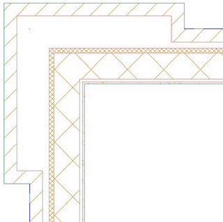
John Mumaw suggested using plan modifiers. Not having much opportunity to do so as part of my work, I took the opportunity to explore his suggested method and failed miserably. I am hoping that he or someone else with extensive plan modifier experience can post a working example of his approach so that I (and others) can reverse engineer what was done and add another weapon to my ADT arsenal.
Undeterred, I fell back on a technique that I have had many occasions to use, wall endcaps. One feature of wall endcaps with which you may be unfamiliar is the option to set a "return offset" on the Dimensions tab when editing a Wall Endcap Style. If you provide a positive number, the endcap moves away from the end of the wall, toward the middle of the wall. A negative number, on the other hand, will move the endcap beyond the end of the wall, and is key to using wall endcaps to simulate cleanup or to get wall components to offset at wall ends, as endcaps are not shown at wall ends that clean up with another wall.
I posted a sample file as a reply in that thread, which includes the walls that generated the image above, as well as the polylines I drew to create the endcap, as shown in the following image.

Note that the polylines all start and end on a line drawn perpendicular to the length of the wall, and that all of the polyline segments have a width of zero, except for the ones along the 45-degree angle. Zero-width segments will be drawn as component edges, when those are set to display. Segments with a width will not be drawn, creating an open condition at the component which can be used to simulate cleanup between walls that have adjoining endcaps.
I used the wall context menu Endcaps > Calculate Automatically to generate the Wall Endcap Style from the polylines I drew, setting it to be an override, as I chose not to make this the style's default endcap condition.
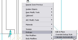
This will create the endcap, but not the offset, and will extend the wall used to create the endcap so that the endcap appears on top of where the polylines were drawn.
Then I opened the Style Manager and found my newly created Wall Endcap Style, under the Architectural Objects folder. In the sample file I posted, the Wall Endcap Style is called "CMU-8 Rigid-1.5 Air-2 Brick-4 Furring Four-Foot Brick Pier Open End Beveled - Projected 56 (End 1)". On the Dimensions tab, I set a Return Offset of -56", so that the entire endcap would project beyond the end of the drawn wall.
 That much of a projection would not be necessary - if you keep the cleanup radii of both walls at zero, any negative projection would do - but I chose to do that so that the wall end has meaning, relative to the brick offset. If you look closely at the first image, you can see that I had the wall graph display toggled on, and the wall end occurs right where the brick offsets. The walls were drawn left justified, so the wall graph line occurs at the outside face of the brick.
Finally, I stretched the wall back down 56" to get the endcap back to its original position and added a second wall, applying the same endcap to the adjoining end.
Check out the Wall Corner Condition thread if you are interested in seeing the sample for yourself, or just to take a good, long laugh at my pathetic attempt to follow Mr. Mumaw's suggestion, as I left those in the file, as well.

John Mumaw suggested using plan modifiers. Not having much opportunity to do so as part of my work, I took the opportunity to explore his suggested method and failed miserably. I am hoping that he or someone else with extensive plan modifier experience can post a working example of his approach so that I (and others) can reverse engineer what was done and add another weapon to my ADT arsenal.
Undeterred, I fell back on a technique that I have had many occasions to use, wall endcaps. One feature of wall endcaps with which you may be unfamiliar is the option to set a "return offset" on the Dimensions tab when editing a Wall Endcap Style. If you provide a positive number, the endcap moves away from the end of the wall, toward the middle of the wall. A negative number, on the other hand, will move the endcap beyond the end of the wall, and is key to using wall endcaps to simulate cleanup or to get wall components to offset at wall ends, as endcaps are not shown at wall ends that clean up with another wall.
I posted a sample file as a reply in that thread, which includes the walls that generated the image above, as well as the polylines I drew to create the endcap, as shown in the following image.
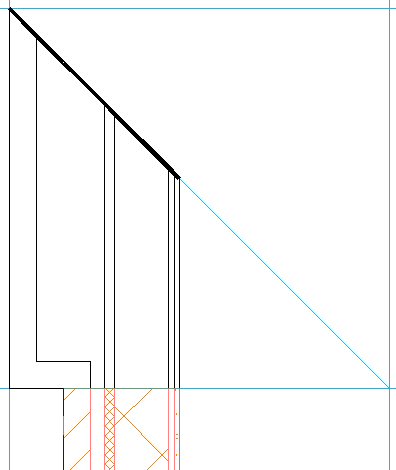
Note that the polylines all start and end on a line drawn perpendicular to the length of the wall, and that all of the polyline segments have a width of zero, except for the ones along the 45-degree angle. Zero-width segments will be drawn as component edges, when those are set to display. Segments with a width will not be drawn, creating an open condition at the component which can be used to simulate cleanup between walls that have adjoining endcaps.
I used the wall context menu Endcaps > Calculate Automatically to generate the Wall Endcap Style from the polylines I drew, setting it to be an override, as I chose not to make this the style's default endcap condition.

This will create the endcap, but not the offset, and will extend the wall used to create the endcap so that the endcap appears on top of where the polylines were drawn.
Then I opened the Style Manager and found my newly created Wall Endcap Style, under the Architectural Objects folder. In the sample file I posted, the Wall Endcap Style is called "CMU-8 Rigid-1.5 Air-2 Brick-4 Furring Four-Foot Brick Pier Open End Beveled - Projected 56 (End 1)". On the Dimensions tab, I set a Return Offset of -56", so that the entire endcap would project beyond the end of the drawn wall.
 That much of a projection would not be necessary - if you keep the cleanup radii of both walls at zero, any negative projection would do - but I chose to do that so that the wall end has meaning, relative to the brick offset. If you look closely at the first image, you can see that I had the wall graph display toggled on, and the wall end occurs right where the brick offsets. The walls were drawn left justified, so the wall graph line occurs at the outside face of the brick.
Finally, I stretched the wall back down 56" to get the endcap back to its original position and added a second wall, applying the same endcap to the adjoining end.
Check out the Wall Corner Condition thread if you are interested in seeing the sample for yourself, or just to take a good, long laugh at my pathetic attempt to follow Mr. Mumaw's suggestion, as I left those in the file, as well.
December 12, 2006
Not Quite 7500...
...but really close. The official tally is in - 7447 total in attendence at Autodesk University 2006. That number includes 5166 attendees, 311 instructors, 648 Autodesk employees and 1322 investors, media, guests, exhibitors (from 89 companies), staff, and other attendees.
December 03, 2006
Agents of Change - Autodesk University 2006
 I had the good fortune to attend Autodesk University 2006 as a last-minute substitute for someone else at my firm who was unable to go. AU returned to Las Vegas for 2006, but at a new venue, The Venetian. Despite a record-breaking number of participants - 7500 was the last number I heard announced - the facility was up to handling it, making an exception for Tuesday's lunch, when the exhibit hall was not yet open to help spread out the arrival time. No one seemed to miss the long haul that had to be made at previous Vegas AU's between the hotel and conference center at the MGM.
This year's theme was "Agents of Change", based on the idea that AU attendees tend to be early adopters of Autodesk's anually-changing software as they deal with the ever-changing challenges and opportunities in the world in general and their particular industries in specific.
This year not only the curriculum, but the physical location of most classes was broken up into industry-specific campuses. For example, the Building campus was located at one end of Level 3, and a lounge dedicated to the Building campus was located directly opposite the classrooms and staffed by Autodesk BSD employees armed with computers to demonstrate the BSD program offerings during the time that classes were offered. This made it much easier to find others in your discipline, both those you already knew and those you wanted to meet.
The Building Industry Main Stage presentation was held Wednesday morning. While I was glad to hear a renewal of the promise to continue developing both the Architectal Desktop and Revit platforms, I was annoyed at the ongoing marketing spin that equates "2D", "CAD drafting" and "AutoCAD for Architects" with Architectural Desktop and "3D" and "Building Information Modeling (BIM)" with Revit. I say that without any animosity toward the Revit product. The class schedule I inherited had mostly Revit or Revit-based classes and I came away impressed with Revit's capabilities. The main stage example for how you can leverage the Revit Building BIM model was the ability to link to 3ds Max and import the cameras and materials, then do renderings and light level analyses in 3ds Max. What a pity that "2D" Architectural Desktop can not do the same. I suppose they forgot that Architectural Desktop files can also be linked to Viz and Max and that, since the 2004 release, Architectural Desktop has shipped with VIZ Render.
Each industry group had its own reception in various venues on Wednesday evening. The Building reception was held at the JET Nightclub in the Mirage, billed on the invitation as "one of the coolest hotspots" and "architecturally stunning". I found it dark (save for pulsating lights on the main floor), loud, crowded and no more architecturally interesting than most any other night club I have visited. Everyone else seemed to be enjoying themselves, so it is probably safe to say the problem was with me, not the event.
The Thursday evening entertainment was fantastic. Engineer/comedian Don McMillan was every bit as funny as he was two years ago, and the Blue Man Group performance was excellent. Autodesk's Shaan Hurley was chosen from the audience to "participate"; you can see photos in this article in his blog. You can find additional photos from AU 2006 in Shaan's AU 2006 Photo Gallery.
Overall, I had a great time at AU 2006 and came away with a lot of valuable knowledge. I was able to meet many people that I only "know" from the Discussion Groups or AUGI forums and chat with some of the people at Autodesk who help produce the software I use at work, Architectural Desktop. If you have a passion for one or more Autodesk products, I would highly recommend attending Autodesk University. At the Thursday night event, Lynn Allen announced that AU 2007 would also be held at The Venetian in Las Vegas, November 26 - 30, 2007. Mark your calendars and start working on a way to get there!
October 31, 2006
Multi-View Block Creation
There have been a number of posts in the Autodesk Architectural Desktop Discussion Groups over the years asking for help in the creation of Multi-View Block Definitions. If you can create an AutoCAD block definition, then you are most of the way there. I am going to assume that you do know how create the AutoCAD blocks that will be used for the Multi-View Block, and will focus on a few tips on creating the blocks and then run through the process of creating the Multi-View Block Definition.
Terminology
The two most important things to keep in mind when creating the view blocks for your MVB are:
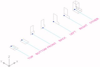
You will also want to give consideration as to whether your MVB needs to display differently when different Display Representations are active. Perhaps your object should have a different top view displays for a regular plan and a reflected ceiling plan. If you have your Display System set up with two Display Representations for MVBs, one of which is only active in the Display Configuration[s] you use for regular plans and the other one of which is only active in the Display Configuration[s] you use for reflected ceiling plans, then you can create separate view blocks and assign each to the Top view direction in its corresponding Display Representation. Also remember that, unlike other ADT objects, the display control for MVBs is limited to assigning view blocks to view directions for the available Display Representations and then choosing which Display Representation[s] to have active for a given Display Representation Set. You can not control layer, color, linetype or plot style as a display setting; you need to set those up in the graphics of the view block. For example, if you want your MVB to plot screened when the Screened Display Represenation is active, then the graphics you use in the view block[s] assigned to the Screened Display Representation must be set up to plot screened, either by direct plot style/color assignment or by using ByLayer graphics on a layer that plots screened. My example MVB has the graphics in the view blocks all set to ByBlock, so that they will inherit the layer, color, linetype, etc, of the parent MVB.
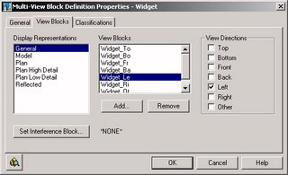
Once the view blocks are defined, the hard work is over. Open up the Style Manager and create a new Multi-View Block definition. Give the definition an appropriate name and description on the General tab. Then select the View Blocks tab, where you will assign the view blocks you created to the appropriate view directions for each Display Representation in which your MVB is to be visible. In my example file, the General Display Representation is used to display the othogonal view blocks, with the "3D block" assigned to the other view direction. The Model Display Representation has the "3D block" assigned to all view directions. Select the desired Display Representation in the left list box, then use the Add... button to select a view block. When adding a view block, the initial default is for all view directions to be selected; left click on the view direction toggles at the right to set or clear each view direction for the selected view block. The images below show the General Display Representation settings for the Widget_To [Top view block], Widget_Fr [Front view block], Widget_Le [Left view block] and Widget_Ot [Other view block]. The settings for the other view directions are similar, with the each block assigned to the appropriate view direction.



The following image shows how the Widget_Ot view block has been assigned to all view directions for the Model Display Represenation.

Select the OK button in the MVB Definition Properties dialog and the OK button in the Style Manager to save your MVB Definition to your drawing. Now would be a good time to save the drawing file, too.
Having defined a new MVB, you will want to test it before using it yourself or distributing it to others. The image below shows a new set of orientation lines, this time with the MVB inserted at the endpoint, then rotated in three dimensions so that, when viewed from the Front predefined view, all seven view blocks will be active at the same time. This allows you to make certain all view blocks were assigned, the correct view block was assigned to each view direction and the view block is properly oriented.
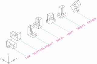
The image below is the result of changing to the Front view and shows that the MVB was created correctly.

Terminology
- MVB - abbreviation used in balance of article for Multi-View Block.
- view block - an AutoCAD block definition assigned to one or more view directions for one or more Display Representations.
- view direction - direction from which the ADT model is being viewed. MVBs allow assigning blocks to be displayed when one of the orthogonal view directions [Top, Bottom, Front, Back, Left or Right] is active, as well as one for "Other" view directions.
- WCS - World Coordinate System, a fixed coordinate system used as the basis for defining all objects and other coordinate systems.
The two most important things to keep in mind when creating the view blocks for your MVB are:
- Maintain an insertion point for all view blocks that is consistent in all three dimensions, preferrably at the MVB insertion point.
- Set the World Coordinate System current when defining the view blocks. The graphics for each orthogonal view block need to be drawn in the plane from which they will be viewed [World X-Y plane for Top and Bottom views, World X-Z plane for Front and Back views and World Y-Z plane for Left and Right views]. It may be advantageous to set an UCS that places the UCS X-Y plane parallel to the plane in which you wish to draw the graphics for a particular view block, but you MUST CHANGE BACK to the WCS before defining the view blocks!

You will also want to give consideration as to whether your MVB needs to display differently when different Display Representations are active. Perhaps your object should have a different top view displays for a regular plan and a reflected ceiling plan. If you have your Display System set up with two Display Representations for MVBs, one of which is only active in the Display Configuration[s] you use for regular plans and the other one of which is only active in the Display Configuration[s] you use for reflected ceiling plans, then you can create separate view blocks and assign each to the Top view direction in its corresponding Display Representation. Also remember that, unlike other ADT objects, the display control for MVBs is limited to assigning view blocks to view directions for the available Display Representations and then choosing which Display Representation[s] to have active for a given Display Representation Set. You can not control layer, color, linetype or plot style as a display setting; you need to set those up in the graphics of the view block. For example, if you want your MVB to plot screened when the Screened Display Represenation is active, then the graphics you use in the view block[s] assigned to the Screened Display Representation must be set up to plot screened, either by direct plot style/color assignment or by using ByLayer graphics on a layer that plots screened. My example MVB has the graphics in the view blocks all set to ByBlock, so that they will inherit the layer, color, linetype, etc, of the parent MVB.
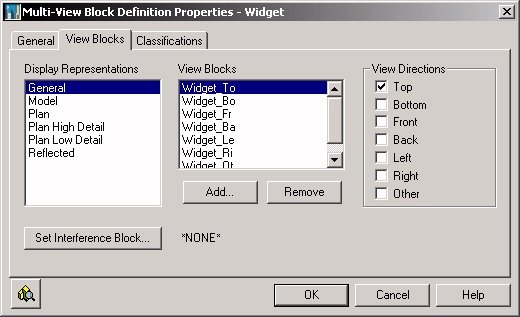
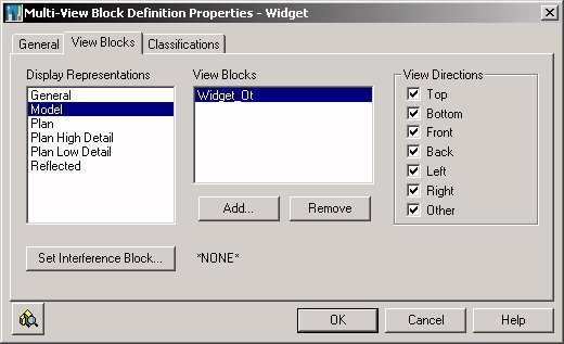
Once the view blocks are defined, the hard work is over. Open up the Style Manager and create a new Multi-View Block definition. Give the definition an appropriate name and description on the General tab. Then select the View Blocks tab, where you will assign the view blocks you created to the appropriate view directions for each Display Representation in which your MVB is to be visible. In my example file, the General Display Representation is used to display the othogonal view blocks, with the "3D block" assigned to the other view direction. The Model Display Representation has the "3D block" assigned to all view directions. Select the desired Display Representation in the left list box, then use the Add... button to select a view block. When adding a view block, the initial default is for all view directions to be selected; left click on the view direction toggles at the right to set or clear each view direction for the selected view block. The images below show the General Display Representation settings for the Widget_To [Top view block], Widget_Fr [Front view block], Widget_Le [Left view block] and Widget_Ot [Other view block]. The settings for the other view directions are similar, with the each block assigned to the appropriate view direction.


The following image shows how the Widget_Ot view block has been assigned to all view directions for the Model Display Represenation.
Select the OK button in the MVB Definition Properties dialog and the OK button in the Style Manager to save your MVB Definition to your drawing. Now would be a good time to save the drawing file, too.
Having defined a new MVB, you will want to test it before using it yourself or distributing it to others. The image below shows a new set of orientation lines, this time with the MVB inserted at the endpoint, then rotated in three dimensions so that, when viewed from the Front predefined view, all seven view blocks will be active at the same time. This allows you to make certain all view blocks were assigned, the correct view block was assigned to each view direction and the view block is properly oriented.

The image below is the result of changing to the Front view and shows that the MVB was created correctly.

October 03, 2006
Auto-Import Layer Key Style
Autodesk Architectural Desktop provides a way to make certain the Layer Key Style in your drawing files reflects the latest revisions without having to manually import the revised Layer Key Style [or even to know that it has been updated]. The image and procedures shown here were created/developed for ADT 2004, but the same feature is available in later releases.
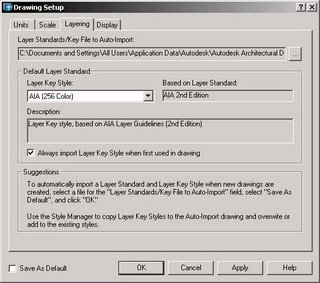 The Layering tab of the Drawing Setup dialog allows you to specify a Layer Standards/Key File to Auto-Import. If you have not done so already, you will want to establish a file to hold your Layer Standard[s] and Layer Key Style[s]. The AecLayerStd.dwg file holds the out-of-the-box Layer Standards and Layer Key Styles. For the 2004 release, on a standalone, local machine installation, this file is located at:
C:\Documents and Settings\All Users\Application Data\Autodesk\Autodesk Architectural Desktop 2004\R16.0\enu\Layers
The path will be similar, with some minor variation in later releases. If you have a customized installation, particularly if some files were placed on the network for common access by all users, this file could be anywhere, but is likely located with your other content files.
If you have customized or plan to customize either the Layer Standard or the Layer Key Style[s], I would highly recommend starting with a copy of the AecLayerStd.dwg file, renamed to reflect that it has your firm's customizations, to make migration to new releases easier. Be certain to back up any customizations, whether to the AecLayerStd.dwg file or your own custom file.
Having identified the name and location of your central source file for Layer Standards and Layer Key Styles, you will want to make that your Auto-Import file by selecting the ellipsis [...] button to the right of the Layer Standards/Key File to Auto-Import area, navigating to your file and selecting it.
Next, set the Layer Key Style from your source file that you wish to be current, using the dropdown list in the Default Layer Standard area. Then note the toggle at the bottom of that area, labeled "Always import Layer Key Style when first used in drawing". Check that toggle if you wish to automatically update your drawing file with any future changes made to the Layer Key Style in the source file. If you want that to be the default condition for all drawings opened on that computer, for that users, also check the Save As Default toggle in the lower left corner. [You may want to check the settings on the other tabs to be certain they have the desired initial default values set before hitting OK, as the Save As Default toggle affects the entire dialog box.]
Here is how this feature works. The first time you issue an ADT command in a given editing session for that drawing [and any other in which the Always import Layer Key Style when first used in drawing toggle is checked], ADT will check the file specified as the Layer Standards/Key File to Auto-Import to see if the Layer Key Style has been edited and saved more recently than the current drawing file. If so, it will automatically import the Layer Key Style from the source file before making use of the referenced Layer Key. If not, the Layer Key Style in the drawing file will be used. No additional checks on the Layer Key Style will be made during that editing session. If you are told the Layer Key Style has been updated while you are editing a file, you can either use the Style Manager to update it from the source file manually, or save [if you want to keep any unsaved changes], close and reopen the file.
This feature is particularly valuable if you are just implementing ADT and make frequent changes to the Layer Key Style to get things "just right" for your office at the same time others are using ADT for production work.
 The Layering tab of the Drawing Setup dialog allows you to specify a Layer Standards/Key File to Auto-Import. If you have not done so already, you will want to establish a file to hold your Layer Standard[s] and Layer Key Style[s]. The AecLayerStd.dwg file holds the out-of-the-box Layer Standards and Layer Key Styles. For the 2004 release, on a standalone, local machine installation, this file is located at:
C:\Documents and Settings\All Users\Application Data\Autodesk\Autodesk Architectural Desktop 2004\R16.0\enu\Layers
The path will be similar, with some minor variation in later releases. If you have a customized installation, particularly if some files were placed on the network for common access by all users, this file could be anywhere, but is likely located with your other content files.
If you have customized or plan to customize either the Layer Standard or the Layer Key Style[s], I would highly recommend starting with a copy of the AecLayerStd.dwg file, renamed to reflect that it has your firm's customizations, to make migration to new releases easier. Be certain to back up any customizations, whether to the AecLayerStd.dwg file or your own custom file.
Having identified the name and location of your central source file for Layer Standards and Layer Key Styles, you will want to make that your Auto-Import file by selecting the ellipsis [...] button to the right of the Layer Standards/Key File to Auto-Import area, navigating to your file and selecting it.
Next, set the Layer Key Style from your source file that you wish to be current, using the dropdown list in the Default Layer Standard area. Then note the toggle at the bottom of that area, labeled "Always import Layer Key Style when first used in drawing". Check that toggle if you wish to automatically update your drawing file with any future changes made to the Layer Key Style in the source file. If you want that to be the default condition for all drawings opened on that computer, for that users, also check the Save As Default toggle in the lower left corner. [You may want to check the settings on the other tabs to be certain they have the desired initial default values set before hitting OK, as the Save As Default toggle affects the entire dialog box.]
Here is how this feature works. The first time you issue an ADT command in a given editing session for that drawing [and any other in which the Always import Layer Key Style when first used in drawing toggle is checked], ADT will check the file specified as the Layer Standards/Key File to Auto-Import to see if the Layer Key Style has been edited and saved more recently than the current drawing file. If so, it will automatically import the Layer Key Style from the source file before making use of the referenced Layer Key. If not, the Layer Key Style in the drawing file will be used. No additional checks on the Layer Key Style will be made during that editing session. If you are told the Layer Key Style has been updated while you are editing a file, you can either use the Style Manager to update it from the source file manually, or save [if you want to keep any unsaved changes], close and reopen the file.
This feature is particularly valuable if you are just implementing ADT and make frequent changes to the Layer Key Style to get things "just right" for your office at the same time others are using ADT for production work.
September 28, 2006
ADT 2007 Service Pack 1 Available
You can now download Service Pack 1 for ADT 2007. Be certain to download and carefully read the Readme for the Service Pack, which provides a listing of the Architectural Desktop and AutoCAD issues that the Service Pack resolves, along with additional known issues not resolved by the Service Pack, instructions on how to install the Service Pack based on the way you installed ADT 2007 and a list of files modified by the Service Pack.
As noted in the Readme, you may need your original installation disk[s] or network image when installing the Service Pack, so be sure to have that handy before you start.
As noted in the Readme, you may need your original installation disk[s] or network image when installing the Service Pack, so be sure to have that handy before you start.
September 09, 2006
List Definitions and Multi-Line Room Names
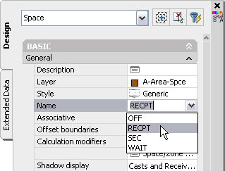
In anticipation of my firm's migration from ADT 2004 to 2007, I was curious as to how we might be best able to take advantage of the addition of an automatic "Name" property for Spaces and the introduction of List Definitions, an expansion of Name Definitions for Areas in previous releases, which now can be applied to Spaces, Zones and/or Manual Properties and can be used to create a predefined list of Names for Spaces.
We currently use a custom room tag based on the out-of-the-box scale-dependent tag, with a second manual property and attribute to support two-line room names, when needed. A formula property combines the contents of the two individual manual properties into one property for use in schedules. You can find a sample file with content similar to what we use in this thread in the Autodesk Architectural Desktop Content Discussion Group. An alternate formula, that can support two, three, or more room name properties/lines, is discussed in this previous article, which contains links to a sample file posted in the ADT Discussion Groups.
Since there is only one "Name" property for Spaces, that would not be compatible with our current methods. I recalled, however, that the Autodesk Knowledge Base for ADT offers another method for creating a two-line room tag that makes use of a single manual property for entering the name and uses MTEXT codes to achieve two or more lines of text. A companion formula property strips out the MTEXT codes for use in a schedule. I just tested this in ADT 2007, with the hope that the List Definition entries could be set up with the MTEXT codes, but it turns out that the backslash character used by the MTEXT codes is not valid.
It looks as though we will have to keep our current set up, possibly adding a List Definition to each of our Manual Properties for room names and remember to train everyone to ignore the Name property on the Design tab of the Properties palette, and keep using our current two Manual Properties on the Extended Data tab.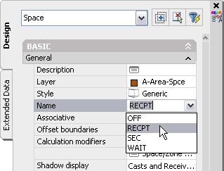
We currently use a custom room tag based on the out-of-the-box scale-dependent tag, with a second manual property and attribute to support two-line room names, when needed. A formula property combines the contents of the two individual manual properties into one property for use in schedules. You can find a sample file with content similar to what we use in this thread in the Autodesk Architectural Desktop Content Discussion Group. An alternate formula, that can support two, three, or more room name properties/lines, is discussed in this previous article, which contains links to a sample file posted in the ADT Discussion Groups.
Since there is only one "Name" property for Spaces, that would not be compatible with our current methods. I recalled, however, that the Autodesk Knowledge Base for ADT offers another method for creating a two-line room tag that makes use of a single manual property for entering the name and uses MTEXT codes to achieve two or more lines of text. A companion formula property strips out the MTEXT codes for use in a schedule. I just tested this in ADT 2007, with the hope that the List Definition entries could be set up with the MTEXT codes, but it turns out that the backslash character used by the MTEXT codes is not valid.

It looks as though we will have to keep our current set up, possibly adding a List Definition to each of our Manual Properties for room names and remember to train everyone to ignore the Name property on the Design tab of the Properties palette, and keep using our current two Manual Properties on the Extended Data tab.
September 03, 2006
NA in Formulas Revisited
I came across an old article on dealing with NA as a potential value in a Formula property. The workaround I suggested, as illustrated in a sample file posted in a reply in the Autodesk Architectural Desktop Discussion Group, made use of the VBScript TypeName function to test whether the value of an automatic property was "Empty", which results in the dreaded NA being displayed in a property, and causes a formula that tries to perform mathematical operations on that value to fail.
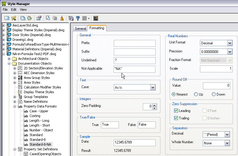
That workaround remains valid, but today it occurred to me that the same approach that Scott Arvin used for the "Cost" examples in his Property Data Enhancements Brain Dump might also work for NA. In the "Cost" example, the ? returned when a property is not attached to a scheduled object will also cause a formula that tries to evaluate it to crash. The ? character that is displayed for Undefined properties is specified in the Property Data Format assigned to the property, as is the NA for Not Applicable properties. You can avoid the crash in either case by creating a Property Data Format that assigns an explicit string to the Undefined and/or Not Applicable properties. You do that by typing in opening and closing double quotes around the text you enter into the associated edit box, as shown for the Not Applicable value in the Standard-8-NA Property Data Format shown in the image below.
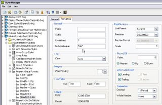
I have made a new reply to the previously mentioned thread which has a sample ZIP file attached that contains NA-in-Formula-Test2.dwg. This is a copy of the previously posted drawing file [2004 format], and contains all of the properties used for the original method, along with two new properties and a new Property Data Format. The Property Data Format is called Standard-8-NA, and is as depicted above. One of the new properties is an Automatic property referencing the Thickness property of doors, called ThicknessUnformatted2, and has the new Standard-8-NA Property Data Format applied. The other new property is a Formula property called ThicknessForSchedule2, and looks like this:
A direct test for "NA" in [ThicknessUnformatted2] worked when the value was Not Available, and therefore "NA", but did not work when the value was a real number, so I changed the test to simply determine whether the type was a string [the TypeName function always returns a string, so a comparison to another string should not cause a failure]. This alternate approach does not require the ThicknessForFormula Formula property that the original one did, but does require a custom Property Data Format. I would call it a draw and suggest you use whichever method seems best to you.
That workaround remains valid, but today it occurred to me that the same approach that Scott Arvin used for the "Cost" examples in his Property Data Enhancements Brain Dump might also work for NA. In the "Cost" example, the ? returned when a property is not attached to a scheduled object will also cause a formula that tries to evaluate it to crash. The ? character that is displayed for Undefined properties is specified in the Property Data Format assigned to the property, as is the NA for Not Applicable properties. You can avoid the crash in either case by creating a Property Data Format that assigns an explicit string to the Undefined and/or Not Applicable properties. You do that by typing in opening and closing double quotes around the text you enter into the associated edit box, as shown for the Not Applicable value in the Standard-8-NA Property Data Format shown in the image below.
I have made a new reply to the previously mentioned thread which has a sample ZIP file attached that contains NA-in-Formula-Test2.dwg. This is a copy of the previously posted drawing file [2004 format], and contains all of the properties used for the original method, along with two new properties and a new Property Data Format. The Property Data Format is called Standard-8-NA, and is as depicted above. One of the new properties is an Automatic property referencing the Thickness property of doors, called ThicknessUnformatted2, and has the new Standard-8-NA Property Data Format applied. The other new property is a Formula property called ThicknessForSchedule2, and looks like this:
If TypeName( [ThicknessUnformatted2] ) = "String" Then
 RESULT = "--"
Else
 RESULT = CDbl( [ThicknessUnformatted2] )
End If
A direct test for "NA" in [ThicknessUnformatted2] worked when the value was Not Available, and therefore "NA", but did not work when the value was a real number, so I changed the test to simply determine whether the type was a string [the TypeName function always returns a string, so a comparison to another string should not cause a failure]. This alternate approach does not require the ThicknessForFormula Formula property that the original one did, but does require a custom Property Data Format. I would call it a draw and suggest you use whichever method seems best to you.
Subscribe to:
Posts (Atom)