
John Mumaw suggested using plan modifiers. Not having much opportunity to do so as part of my work, I took the opportunity to explore his suggested method and failed miserably. I am hoping that he or someone else with extensive plan modifier experience can post a working example of his approach so that I (and others) can reverse engineer what was done and add another weapon to my ADT arsenal.
Undeterred, I fell back on a technique that I have had many occasions to use, wall endcaps. One feature of wall endcaps with which you may be unfamiliar is the option to set a "return offset" on the Dimensions tab when editing a Wall Endcap Style. If you provide a positive number, the endcap moves away from the end of the wall, toward the middle of the wall. A negative number, on the other hand, will move the endcap beyond the end of the wall, and is key to using wall endcaps to simulate cleanup or to get wall components to offset at wall ends, as endcaps are not shown at wall ends that clean up with another wall.
I posted a sample file as a reply in that thread, which includes the walls that generated the image above, as well as the polylines I drew to create the endcap, as shown in the following image.
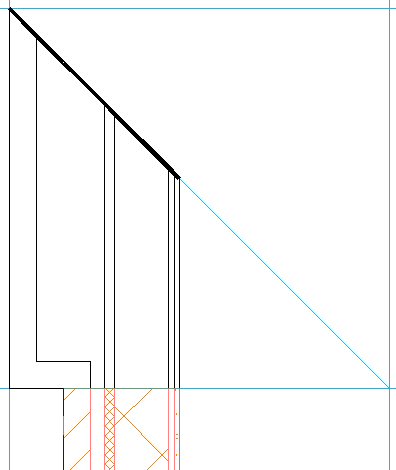
Note that the polylines all start and end on a line drawn perpendicular to the length of the wall, and that all of the polyline segments have a width of zero, except for the ones along the 45-degree angle. Zero-width segments will be drawn as component edges, when those are set to display. Segments with a width will not be drawn, creating an open condition at the component which can be used to simulate cleanup between walls that have adjoining endcaps.
I used the wall context menu Endcaps > Calculate Automatically to generate the Wall Endcap Style from the polylines I drew, setting it to be an override, as I chose not to make this the style's default endcap condition.

This will create the endcap, but not the offset, and will extend the wall used to create the endcap so that the endcap appears on top of where the polylines were drawn.
Then I opened the Style Manager and found my newly created Wall Endcap Style, under the Architectural Objects folder. In the sample file I posted, the Wall Endcap Style is called "CMU-8 Rigid-1.5 Air-2 Brick-4 Furring Four-Foot Brick Pier Open End Beveled - Projected 56 (End 1)". On the Dimensions tab, I set a Return Offset of -56", so that the entire endcap would project beyond the end of the drawn wall.
 That much of a projection would not be necessary - if you keep the cleanup radii of both walls at zero, any negative projection would do - but I chose to do that so that the wall end has meaning, relative to the brick offset. If you look closely at the first image, you can see that I had the wall graph display toggled on, and the wall end occurs right where the brick offsets. The walls were drawn left justified, so the wall graph line occurs at the outside face of the brick.
Finally, I stretched the wall back down 56" to get the endcap back to its original position and added a second wall, applying the same endcap to the adjoining end.
Check out the Wall Corner Condition thread if you are interested in seeing the sample for yourself, or just to take a good, long laugh at my pathetic attempt to follow Mr. Mumaw's suggestion, as I left those in the file, as well.
No comments:
Post a Comment