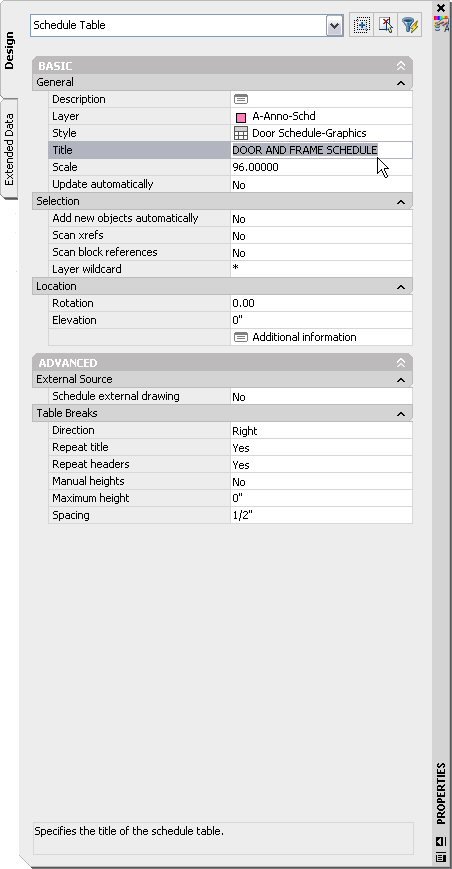
- Table Title Overrides: In previous releases, the title for the schedule table specified on the Layout tab when editing a Schedule Table Style was the title used for all instances of that style. If you wanted otherwise identical schedules with different titles, such as "First Floor Door Schedule", "Second Floor Door Schedule", etc., you would have to copy the style for each unique title. ADT 2007 now provides for a table title override. The title specified in the Schedule Table Style is the initial title, but you can change it on the Properties palette, using the Title property in the General section, as shown in the image below.

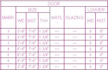
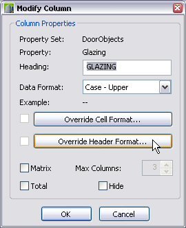
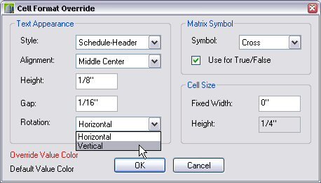
- Header Overrides: In previous versions of ADT, the formatting overrides for headers was limited to making all headers of the same type [Column or Matrix] the same. In ADT 2007, you can still set global overrides on the Layout tab, but you can also override the formatting on each column individually. This is great if you have a column with "narrow" data but a "wide" header, you can now set the rotation of that single column to vertical, without affecting all of the other headers of the same type.
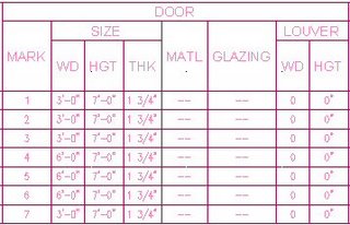 Schedule Table Before Header Override
 Header Override Button in Modify Column Dialog
 Setting a Vertical Rotation
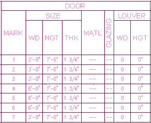 Schedule Table After Header Override
You can also set the header override at the time you create the column. - Formula Columns: Another often requested item has been to be able to use the value in the quantity column in a formula property. You still can not do that, but there is an alternative that is very close. In previous versions, you were limited to adding a Product column, in which you could multiply the value in any other column in the Schedule Table by the Quantity. Product columns have been replaced by the new Formula columns, which, as the name implies, allows you to create a column that displays the result of a formula. Since this formula is in the Schedule Table itself, the quantity value is available, and can be added using the Insert Quantity button.
The image below shows the Columns tab of a Schedule Table Style for equipment that has two formula columns at the far right, Net Price and Total Price.
The Net Price value is determined by a formula. If the quantity for a given equipment item is less than three items, then the net price is the list price. If three or more items are included, the net price is 85% of the list price.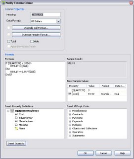
You can not reference another column in a formula column, but you can reference any of the properties in Property Set Definitions that could be added to the Schedule Table Style as a column. This is why my Total Cost column formula, shown below, repeats the same test as the Net Cost formula, rather than referencing the Net Cost column value directly.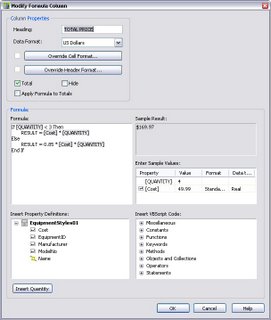
If you reference a numeric property in a formula column formula and intend to perform mathematical operations on it, you will need to use an "unformatted" property, just as you would in a formula property. The Cost property has a Property Data Format called "Standard - 02", which is a copy of the out-of-the-box "Standard" Property Data Format, with the precision set to 0.00 and the rounding set to 0.01. You can read more about using unformatted properties in this previous blog article. The Property Data Format applied to the Cost property column in the Schedule Table Style is not the default from the PSD but "US Dollars", a custom format I set up to display US currency. The image below shows the resulting schedule table in a sample file that has three different types of equipment.
April 08, 2006
Enhanced Property Data Features in ADT 2007, Part 5
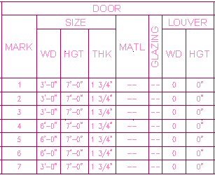
This post will cover the three improvements made to Schedule Tables.





March 31, 2006
Enhanced Property Data Features in ADT 2007, Part 4
A new object type has been added to ADT 2007, the List Definition. If you used the Area object in previous releases of ADT, you may be familiar with Name Definitions, which allowed you to create a list of names that could be used for areas attached to an area group, with a specific name selected from a dropdown list in the Properties palette. The new List Definition object takes over that role in ADT 2007 and expands it by allowing you to assign a List Defintion to a Manual property in a Property Set Defintion. This will allow you to offer your users the long-requested ability to choose a value from a drop-down list, rather than having to type the values in manaully each time, introducing the probability of typographic errors.
List Definition objects are created and edited in the Style Manager, and can be found under the Multi-Purpose Objects folder. [Name Definitions used to be under the Documentation Objects folder.] The General tab offers the usual opportunity to edit the Name and Description of your List Definition. The Applies To tab, shown below, allows you to specify to which object types the list will apply: Manual Property Definitions, Space Names [the 2007 equivalent of Area names - you have heard that Spaces, Areas and ABS Spaces have all merged into one object in 2007, haven't you?] and/or Zone Names [the 2007 equivalent to Area Groups and ABS Zones]. Note that unlike previous versions of ADT, the default initial state of the Applies To tab is to have all choices NOT selected. This holds true when creating other styles or defintions with an Applies To tab, like Property Set Defintions and Schedule Table Styles. The Select All and Clear All buttons are still there [but not shown in the image]. This is a welcome change, as most times you will want the new style/defintion to apply to only a few of the choices, at most. You no longer have to hit Clear All first, then make your choices.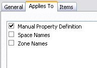
You create the actual list entries on the Items tab. The Add and Remove buttons allow you to add new entries and remove existing entries, respectively. When checked, the "Allow individual property values to vary from this list" toggle permits the user to manually type in a value, in addition to selecting it from the list.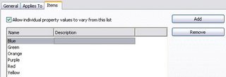
Once you have a List Defintion that applies to Manual Property Defintions set up and populated with values, it is ready to be assigned to a Manual property. To do so, create the Manual property or edit an existing one, and set/change the property Type to "List" by selecting it from the drop down list as shown below. If you have more than one List Defintion in your drawing file, you can specify which list to use in the Source column, set a default value in the Default column, apply a Property Data Format in the Format column, look at the effect of the Property Data Format in the Example column and set the visibility and order as noted in Part 1 of this series.
When you attach the Property Set containing your new List-type Manual property to an object [or a style] of the type to which the Property Set applies, you can set the value for the new manual property. Do this by selecting a value from the dropdown list in the Edit Property Set Data dialog...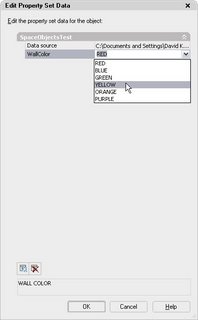 ...or the Properties palette.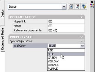
If you checked the toggle to allow values to vary from the list, you can also type in a value not on the list.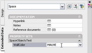
Three cheers for the ADT Development Team in crossing off another wish list item.
List Definition objects are created and edited in the Style Manager, and can be found under the Multi-Purpose Objects folder. [Name Definitions used to be under the Documentation Objects folder.] The General tab offers the usual opportunity to edit the Name and Description of your List Definition. The Applies To tab, shown below, allows you to specify to which object types the list will apply: Manual Property Definitions, Space Names [the 2007 equivalent of Area names - you have heard that Spaces, Areas and ABS Spaces have all merged into one object in 2007, haven't you?] and/or Zone Names [the 2007 equivalent to Area Groups and ABS Zones]. Note that unlike previous versions of ADT, the default initial state of the Applies To tab is to have all choices NOT selected. This holds true when creating other styles or defintions with an Applies To tab, like Property Set Defintions and Schedule Table Styles. The Select All and Clear All buttons are still there [but not shown in the image]. This is a welcome change, as most times you will want the new style/defintion to apply to only a few of the choices, at most. You no longer have to hit Clear All first, then make your choices.

You create the actual list entries on the Items tab. The Add and Remove buttons allow you to add new entries and remove existing entries, respectively. When checked, the "Allow individual property values to vary from this list" toggle permits the user to manually type in a value, in addition to selecting it from the list.

Once you have a List Defintion that applies to Manual Property Defintions set up and populated with values, it is ready to be assigned to a Manual property. To do so, create the Manual property or edit an existing one, and set/change the property Type to "List" by selecting it from the drop down list as shown below. If you have more than one List Defintion in your drawing file, you can specify which list to use in the Source column, set a default value in the Default column, apply a Property Data Format in the Format column, look at the effect of the Property Data Format in the Example column and set the visibility and order as noted in Part 1 of this series.

When you attach the Property Set containing your new List-type Manual property to an object [or a style] of the type to which the Property Set applies, you can set the value for the new manual property. Do this by selecting a value from the dropdown list in the Edit Property Set Data dialog...
 ...or the Properties palette.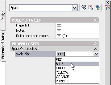
If you checked the toggle to allow values to vary from the list, you can also type in a value not on the list.

Three cheers for the ADT Development Team in crossing off another wish list item.
March 24, 2006
Enhanced Property Data Features in ADT 2007, Part 3
Here is another new feature related to property data, coming your way in the soon to be released ADT 2007. You can now specify a Unit Type when setting up a Property Data Format, so that ADT "knows" what type of data to expect for that property. Please note that the Unit Types ONLY apply to manual properties, and only those set to the "Real" type. Auto Increment - Character, Auto Increment - Integer, Integer, Text and True/False types of manual properties do not make use of this new feature. You set the Unit Type in the Real Numbers area of the Formatting tab when editing the Property Data Format, as seen in the image below. The image also displays the list of different Unit Types available.

Each Unit Type then has an associated list of Units relevant to that type. You set a "default" Unit value in the PDF, and this will be used when first assigning a PDF to a new property. Once the property has a value assigned, that value "sticks" when changing to a new PDF, rather than changing to the default value of the new PDF, if the Unit Type is the same for both old and new PDFs. The Units available for the Length Unit Type can be seen in the image below.

Once you assign a PDF to a Real manual property, you can change the Units to any of those available for the assigned Unit Type in the Units column on the Definition tab, when editing a Property Set Defintion. Simply click on the current value to activate a dropdown list of available values. I will repeat that this only applies to Real manual properties; formula properties will be blank in the Units column, and the Automatic properties will list "dimensionless" but not offer any other choices in a dropdown list, as shown in the image below.

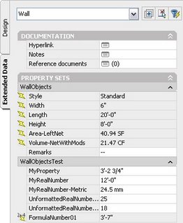
The final image shows the Extended Data tab for a wall that has the Property Set shown above attached. MyProperty and MyRealNumber both have the Length - Long Property Data Format attached, which uses the Architectural Unit Format and the Length Unit Type. MyProperty uses the default inches for the Unit, while MyRealNumber was changed to feet. The value typed into MyProperty was 38.75; the value typed into MyRealNumber was 12. These display as 3'-2 3/4" and 12'-0", respectively.
Note that if you want to use a number for mathematical purposes in a formula, you will want to stay away from the Architectural and Engineering Unit Formats, which convert numbers to imperial feet and inches format, which will be interpreted as a string, as well as avoiding text prefixes or suffixes. But you CAN use the Decimal Unit Format and assign a Unit Type and Units, such as Length and Inches, without creating a string. You can also choose to set the Unit Type to "(none)", as the out-of-the-box Standard Property Data Format does. This shows in the Units column of a Property Set Defintion as "dimensionless".
Also note that the Unit Type/Units settings affect the way the numbers input are interpreted, but not necessarily the way they are displayed. If your drawing units are inches, but you set up a Real manual property, in Decimal Unit Format, with units of Feet, when you enter the number, you are entering the value in feet, but after you hit return, the value will be displayed in inches [and the value will be twelve times bigger than you entered, since there are twelve inches in a foot]. Unless you have a specific case where you want to enter metric values, but display them in feet and inches, I would not recommend mixing the Architectural or Engineering Unit Format with a Length Unit Type and one of the metric units. I tried that, using Architectural with millimeters, and an entry of 1000 [mm] was displayed as 3'-3 3/8".
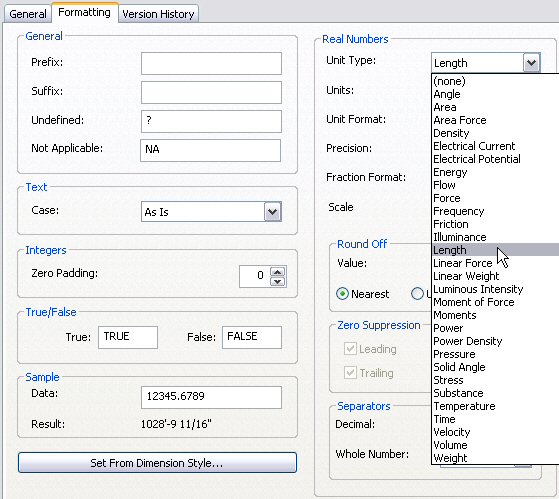
Each Unit Type then has an associated list of Units relevant to that type. You set a "default" Unit value in the PDF, and this will be used when first assigning a PDF to a new property. Once the property has a value assigned, that value "sticks" when changing to a new PDF, rather than changing to the default value of the new PDF, if the Unit Type is the same for both old and new PDFs. The Units available for the Length Unit Type can be seen in the image below.
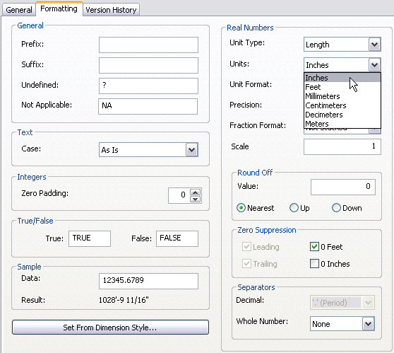
Once you assign a PDF to a Real manual property, you can change the Units to any of those available for the assigned Unit Type in the Units column on the Definition tab, when editing a Property Set Defintion. Simply click on the current value to activate a dropdown list of available values. I will repeat that this only applies to Real manual properties; formula properties will be blank in the Units column, and the Automatic properties will list "dimensionless" but not offer any other choices in a dropdown list, as shown in the image below.

The final image shows the Extended Data tab for a wall that has the Property Set shown above attached. MyProperty and MyRealNumber both have the Length - Long Property Data Format attached, which uses the Architectural Unit Format and the Length Unit Type. MyProperty uses the default inches for the Unit, while MyRealNumber was changed to feet. The value typed into MyProperty was 38.75; the value typed into MyRealNumber was 12. These display as 3'-2 3/4" and 12'-0", respectively.

Note that if you want to use a number for mathematical purposes in a formula, you will want to stay away from the Architectural and Engineering Unit Formats, which convert numbers to imperial feet and inches format, which will be interpreted as a string, as well as avoiding text prefixes or suffixes. But you CAN use the Decimal Unit Format and assign a Unit Type and Units, such as Length and Inches, without creating a string. You can also choose to set the Unit Type to "(none)", as the out-of-the-box Standard Property Data Format does. This shows in the Units column of a Property Set Defintion as "dimensionless".
Also note that the Unit Type/Units settings affect the way the numbers input are interpreted, but not necessarily the way they are displayed. If your drawing units are inches, but you set up a Real manual property, in Decimal Unit Format, with units of Feet, when you enter the number, you are entering the value in feet, but after you hit return, the value will be displayed in inches [and the value will be twelve times bigger than you entered, since there are twelve inches in a foot]. Unless you have a specific case where you want to enter metric values, but display them in feet and inches, I would not recommend mixing the Architectural or Engineering Unit Format with a Length Unit Type and one of the metric units. I tried that, using Architectural with millimeters, and an entry of 1000 [mm] was displayed as 3'-3 3/8".
March 21, 2006
Enhanced Property Data Features in ADT 2007, Part 2
Here are two more Property Data features to look forward to in ADT 2007. Two new property types have been added:
 - Anchor properties
 - Graphic properties
Anchor properties allow you to read in property data into an object from another object to which the first object is anchored. For example, a door anchored to a wall can read property data from the wall, such as the fire-resistance rating of the wall. This was possible in ADT 2004-2006, by using some VBScript code in a formula property - see this thread in the ADT 2006 Discussion Group if you are interested - but the code was version-specific [different for 2004, 2005 and 2006], and for the 2004 and 2005 versions, would not work across external references. The new anchor property does away with all of the formula coding, and lets you choose a property from an existing property set just like you do for location properties, as shown in the Anchor Property Definition dialog below:
 - Anchor properties
 - Graphic properties
Anchor properties allow you to read in property data into an object from another object to which the first object is anchored. For example, a door anchored to a wall can read property data from the wall, such as the fire-resistance rating of the wall. This was possible in ADT 2004-2006, by using some VBScript code in a formula property - see this thread in the ADT 2006 Discussion Group if you are interested - but the code was version-specific [different for 2004, 2005 and 2006], and for the 2004 and 2005 versions, would not work across external references. The new anchor property does away with all of the formula coding, and lets you choose a property from an existing property set just like you do for location properties, as shown in the Anchor Property Definition dialog below:

Graphic properties allow you to add graphics to your schedule table, by specifying either a block or an image to be displayed in the table. When creating a graphic property, you will be asked to provide a default block or image, but when you attach the property set to a style or object, you can accept the default or choose another, specific to that style/object. The layer key chosen will be applied to the blocks; if you freeze that layer, the blocks will also be frozen [and disappear].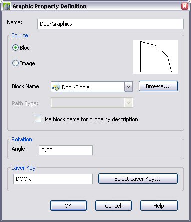
As an example, I made a copy of the out-of-the-box "DoorStyles" Property Set Definition, and added a graphic property, "DoorGraphics". I made three plan-view blocks for doors, one each for a single door, double door and double egress door. The block graphics were all drawn on layer 0, with ByBlock attributes, so they will pick up the layer attributes of the layer associated with the chosen layer key - DOOR. I set the "Door - Single" block as the default block.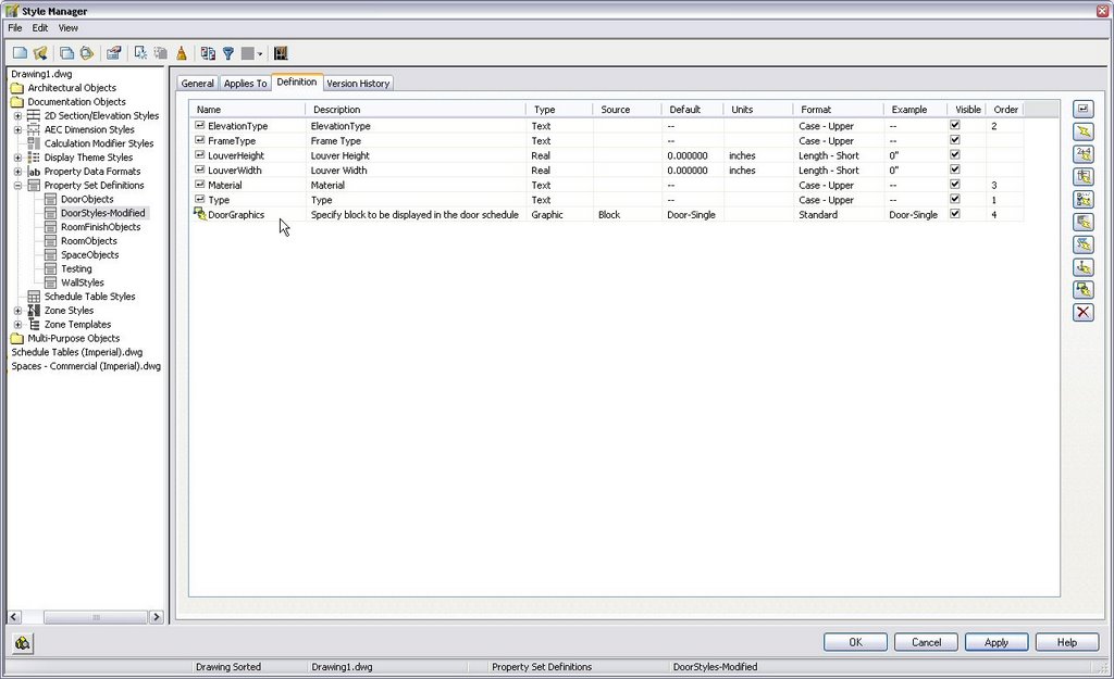
In my test file, I added a few doors of each type, then edited the door styles and added my "DoorStyles-Modified" Property Set to each, selecting the appropriate block for the double and double egress doors and accepting the default for the single doors. The Graphic Property dialog that appears is identical to the Graphic Property Definition dialog, except for the name. I then modified a copy of the out-of-the-box "Door Schedule" Schedule Table Style and added a new column referencing the DoorStyles-Modified:DoorGraphics property. The image below shows the part of the resultant door schedule. The graphics appear on the A-Door layer [which gets created, if necessary]. Note that the blocks are scaled to fit the height and width of the column, so the double egress block appears "smaller" than the other two, even though the doors swing graphics are copies, because the overall block is taller.
Also note that the blocks must exist in the drawing in order to be able to assign them to a style/object and for them to appear in the schedule. So if you create the schedule in a file that uses external references [Xrefs] in the file with the schedule, or references an external file, you will not get the images until you manually copy the blocks to the file with the schedule. If you assign a block to a graphic property in a style-based Property Set, as I did, and then use Style Manager to copy the style to a new drawing, the block name will go along with the copied style, but the block definition does not, and must be manually copied if you want to place an instance of the schedule in that file.
March 11, 2006
Enhanced Property Data Features in ADT 2007, Part 1
My apologies for my month-long gap in posts, but I spent all my "free" time this past month racing against a deadline at work [with a break last Saturday for my mother-in-law's 90th birthday party], and was not able to jump in when the embargo on the 2007 products was lifted. I will try to make up for that in the coming weeks.
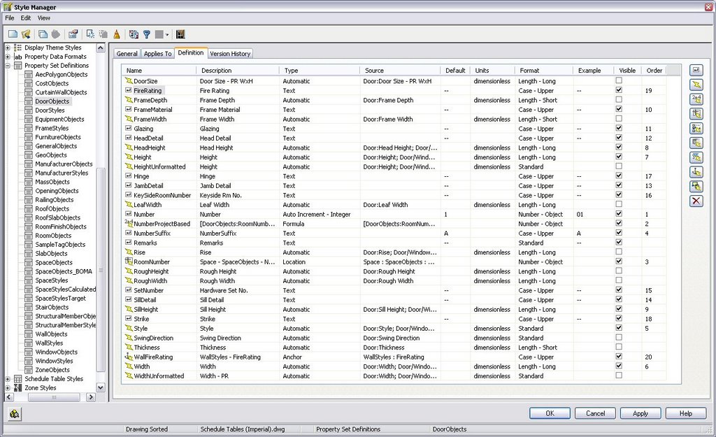
Here is a quick look at two new features added to Property Sets. As you can see in the screen capture of the out-of-the-box DoorObjects Property Set, there are two new columns at the right of the Definition tab: Visibility and Order.
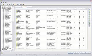
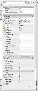
Visibility lets you tell ADT whether a property should be displayed on the Extended Data tab of the Properties Palette or in the Edit Property Set Data dialog that appears when you tag an object. Notice that a number of the automatic properties are not checked - these will not be visible when editing the properties. This can be especially effective for automatic properties, that you can not edit anyway.
The Order column lets you decide the order in which the properties that are visible appear on the the Extended Data tab of the Properties Palette and the Edit Property Set Data dialog. You could choose to group similar properties, or put all of the manual properties together at the top - in a logical order of data entry, rather than alphabetical order, making it easier for the user to enter the data needed.
Here is a quick look at two new features added to Property Sets. As you can see in the screen capture of the out-of-the-box DoorObjects Property Set, there are two new columns at the right of the Definition tab: Visibility and Order.
Visibility lets you tell ADT whether a property should be displayed on the Extended Data tab of the Properties Palette or in the Edit Property Set Data dialog that appears when you tag an object. Notice that a number of the automatic properties are not checked - these will not be visible when editing the properties. This can be especially effective for automatic properties, that you can not edit anyway.
The Order column lets you decide the order in which the properties that are visible appear on the the Extended Data tab of the Properties Palette and the Edit Property Set Data dialog. You could choose to group similar properties, or put all of the manual properties together at the top - in a logical order of data entry, rather than alphabetical order, making it easier for the user to enter the data needed.

February 12, 2006
Links to the "Placing Walls on a Layer Other Than A-Wall..." Series
To make it easier to refer to all three articles in the Placing Walls on a Layer Other Than A-Wall... series, this post has links to all three articles:
Part 1 of 3: Placing Walls on a Layer Other Than A-Wall...
Part 2 of 3: Placing Walls on a Layer Other Than A-Wall...
Part 3 of 3: Placing Walls on a Layer Other Than A-Wall...
Do not forget that while the example deals with walls, the same principles can be applied to other object types, as well.
Part 1 of 3: Placing Walls on a Layer Other Than A-Wall...
Part 2 of 3: Placing Walls on a Layer Other Than A-Wall...
Part 3 of 3: Placing Walls on a Layer Other Than A-Wall...
Do not forget that while the example deals with walls, the same principles can be applied to other object types, as well.
February 09, 2006
Part 3 of 3: Placing Walls on a Layer Other Than A-Wall…
In Part 3, we will wrap up the series on placing a wall on the layer you want it by looking at the second option of the second case, where you want most of your walls to use the layer specified by the WALL Layer Key, but have some walls use a different layer. In Part 2, the use of tool-based temporary Layer Key Overrides was examined, and it was noted that the override only changes the name, not the layer attributes [color, linetype, etc.]. To have Autodesk Architectural Desktop create an alternate layer with the desired attributes, you can create a new Layer Key and have your wall tool reference that key. Keep in mind, if a layer of the name specified by your new Layer Key already exists in the drawing, the wall will be drawn on that layer, but the layer attributes will remain as set in the drawing, even if the Layer Key specifies other values. This is true for the out-of-the-box WALL Layer Key as well, so it should not be a surprise, but is worth mentioning here before we get started.
Using a Tool to Change the Layer – Alternate Layer Key
If you need different layer settings for your alternate wall layer, and you do not want to include the layer in your template file or rely on the end user remembering to run a script or standards check, you can add a new Layer Key, with the desired layer settings, to your Layer Key Style, then set up a wall tool that uses the new Layer Key.
That wraps up this series on putting walls on the layer on which you want them. If you still have questions, a good place to get an answer is in the Autodesk Architectural Desktop Discussion Groups.
Using a Tool to Change the Layer – Alternate Layer Key
If you need different layer settings for your alternate wall layer, and you do not want to include the layer in your template file or rely on the end user remembering to run a script or standards check, you can add a new Layer Key, with the desired layer settings, to your Layer Key Style, then set up a wall tool that uses the new Layer Key.
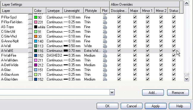
- First, decide the layer name and the attributes you wish to assign to that layer. In keeping with the example from the previous installment, the example here will set up a layer named A-Wall-E for use by existing-to-remain walls. The following attributes will be assigned:
- Color: 116
- Linetype: Continuous
- Lineweight: 0.70 mm
- Plotstyle: Extra Wide Screened
- Plot: Yes
- Allow Overrides: Yes for all
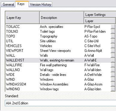
- You will also need to select a name and description for your new Layer Key. For our example, WALLEXIST and “Walls, existing-to-remain” will do. As before, I would recommend working on a renamed copy of your Layer Key Style in a local file while making your edits and only copying it back to your Auto-Import file [see the first article for more on that] once you are satisfied it works. Open the Style Manager, make a copy of the Layer Key Style if desired, and edit the style. On the Keys tab, select the Add… button and enter the name of your new Layer Key in the Name dialog box.
- Scroll in the Keys tab, if needed, to find your newly added key. Left click in the Description column next to your key and add your description.
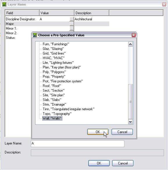
- If your layer name can be built from predefined values for the various Descriptive Components, you can click on the ellipsis button [“…”] and use the Layer Name dialog to build your layer name. In the Layer Name dialog, select the ellipsis button next to each Field to choose from a list of pre-specified values for that field. Otherwise, you can click in the Layer column and type in the layer name.
- Enter the layer parameters for your new Layer Key. You will notice that the Allow Overrides toggles are grayed out. In 2006, click on the Apply button to “register” the new key and enable the toggles. In 2004 and 2005, you will need to select OK, then edit the Layer Key Style again to enable the toggles. OK out to the drawing, and save the drawing file.
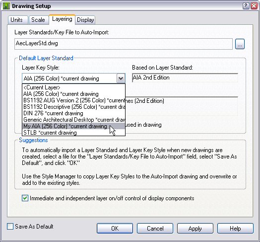
- Set your new Layer Key Style current, by opening the Drawing Setup dialog [one way is to select Format > Drawing Setup… from the pulldown menus] and selecting the Layering tab. In the Default Layer Standard area, choose your new Layer Key Style from the Layer Key Style dropdown list. Select OK to set that style current.
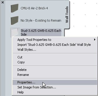
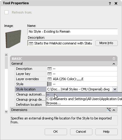
- Now that you have created a new Layer Key, you need to make use of it. On an editable Tool palette, create a wall tool that references a style that you would like to have placed on your alternate layer. Right click on the tool, and choose Properties… from the context menu.
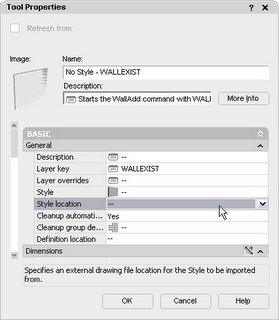
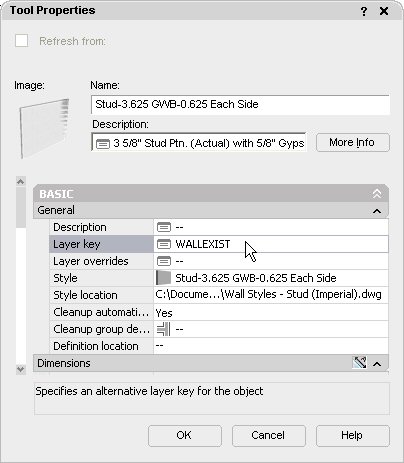
- In the Basic category, General subcategory, the second property is “Layer key”.
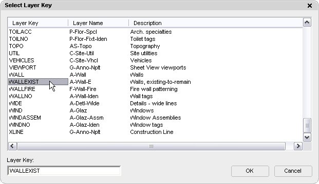
 Left click on the worksheet icon to the right of the Layer key property name to open the Select Layer Key Dialog, which will display a list of the Layer Keys in the current Layer Key Style, along with the layer names and descriptions assigned to each key. Scroll down, if necessary, to find your new Layer Key on the list and select it. The Layer Key Name will appear in the Layer Key edit box at the bottom of the dialog. You can, if you like, also type the name directly into the edit box, but be aware that any entry will be accepted, so if you want to be certain you specify a Layer Key that exists in the current Layer Key Style, find and select the Layer Key from the list. When the desired Layer Key is displayed in the Layer Key edit box, select OK to return to the Tool Properties dialog.
 - Note that your new Layer Key has been assigned to the tool. Select OK to accept the change and close the Tool Properties dialog
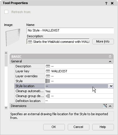
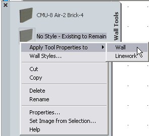
- As with the Layer Override tool, if you expect to have many different walls styles using your new layer key, you may not want to create second set of tools that use this key. [For the current example, if you display components in your plans, you may want to have parallel styles for existing-to-remain walls so that you can assign Material Definitions that display as proper existing walls – even if that means turning off the components. In that case, you would need a new tool for each new style.] You can create a generic wall tool, with no style or style source assigned, then use that tool to start the WallAdd command, choosing a style on the Properties palette, or right click on the tool and choose Apply Tool Properties to > Wall to move a previously drawn wall to the layer specified by the Layer Key set in the wall tool.




That wraps up this series on putting walls on the layer on which you want them. If you still have questions, a good place to get an answer is in the Autodesk Architectural Desktop Discussion Groups.
February 07, 2006
Part 2 of 3: Placing Walls on a Layer Other Than A-Wall…
Welcome back for Part 2. The second case has two options of its own. Which you choose to use will depend upon your exact needs and whether you have layers preloaded into your template files or some other way of easily assuring that the correct layer attributes are assigned. My preference is to leave the template files as lean as possible, but you or your office may have a differing opinion. The introduction of Tool palettes in Autodesk Architectural Desktop 2004 provided a way to assign a temporary Layer Key Override or an entirely new Layer Key. Part 2 will examine the Layer Key Override option.
Using a Tool to Change the Layer – Layer Key Override
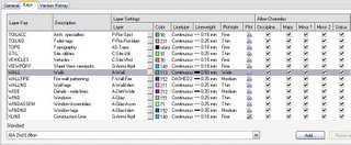
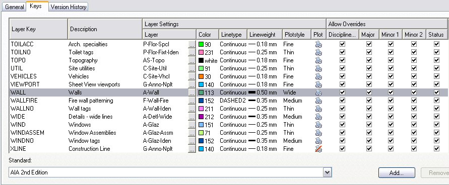
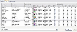
In order for this to work, you have to be using a Layer Key Style that permits overrides on the Descriptive Field you wish to override. You can check this by editing the Layer Key Style and looking at the Layer Key of interest on the Keys tab. The Allow Overrides columns are at the far right of the edit window. As shown below, there is a column for each Descriptive Field in the Layer Standard associated with the Layer Key Style; a checkmark in a column indicates that overrides are permitted. The AIA (256 Color) Layer Key Style shown permits overrides in all of the Descriptive Fields for the WALL key, so we can proceed.
For illustration purposes, lets assume you are using the AIA (256 Color) Layer Key Style and are perfectly happy with new walls being assigned to the A-Wall layer, but want your existing-to-remain walls assigned to A-Wall-E, and want that layer to have a different color, lineweight and plot style.
The next and final installment will cover setting up and assigning a new layer key in a wall tool.
Using a Tool to Change the Layer – Layer Key Override
In order for this to work, you have to be using a Layer Key Style that permits overrides on the Descriptive Field you wish to override. You can check this by editing the Layer Key Style and looking at the Layer Key of interest on the Keys tab. The Allow Overrides columns are at the far right of the edit window. As shown below, there is a column for each Descriptive Field in the Layer Standard associated with the Layer Key Style; a checkmark in a column indicates that overrides are permitted. The AIA (256 Color) Layer Key Style shown permits overrides in all of the Descriptive Fields for the WALL key, so we can proceed.
For illustration purposes, lets assume you are using the AIA (256 Color) Layer Key Style and are perfectly happy with new walls being assigned to the A-Wall layer, but want your existing-to-remain walls assigned to A-Wall-E, and want that layer to have a different color, lineweight and plot style.
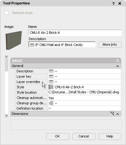
- You have checked the Layer Key Style and confirmed that it is set up to allow Layer Key Overrides to the Status Descriptive Field [see image above]. Now you need to set up a Tool palette tool that will create a wall but apply an override to the Status Descriptive Field so that it is placed on A-Wall-E. I i-dropped a tool for the out-of-the-box “CMU-8 Air-2 Brick-4” wall style onto a newly created [editable] tool palette from the out-of-the-box Design Tool Catalog – Imperial Tool Catalog. Create a wall tool using a style that you want to be able to draw on an alternate layer, right click on it and choose Properties… from the context menu.
- In the Tool Properties dialog, the first category is Basic, and the first subcategory in Basic is General. The third property in General is “Layer overrides”; this is the property we will be modifying.
- Click on the worksheet icon in the Layer overrides edit box to set the override[s] you want. The Select Layer Overrides worksheet will appear.
 If the “Do not specify Layer Overrides” toggle at the bottom of the worksheet is checked, left click on it to clear the check mark and unlock the edit box. You can now specify overrides for any of the Descriptive Fields on which your Layer Key Style permits overrides; in the example here, any of them. Our goal is to change the Status to “E” – you can either left click in the Override column, on the Status row, and type in “E” [without the quotation marks], or, if you know that the override you are applying has been entered as a predefined value for that Descriptive Field in the Layer Standard, select the ellipsis button [“…”] and the Choose a Prespecified Value dialog will appear, with a list of the values that have been prespecified for that Descriptive Field, including their descriptions. This may not seem such a big deal for our example, which only has one character and a fairly limited number of choices, but for the minor fields, with four characters and many more choices, it can be quite helpful. It is also good practice to assure that the layer you are creating conforms to your office’s Layer Standard, which should be set up with predefined values for all of the layers you use. If the list is too long for the dialog, you can use the scroll bars, or start typing the first character or two to home in on the value you want.
 - Select OK in the Choose a Prespecified Value dialog if you used it, and note that the override value now appears in the Select Layer Overrides worksheet. You can specify overrides for as many fields as you like; our example only requires overriding the Status Descriptive Field, so no additional settings need to be made.
- Select OK in the Select Layer Overrides worksheet to return to the Tool Properties dialog. Note that the Layer overrides edit box now contains a value, indicating the Layer Key Style to which the override applies followed by the override values, each separated by a comma. In our example, there are a number of commas in a row; the fact that there are no values between the commas indicates that those fields have no override. The “E” at the end indicates that the last Descriptive Field [Status] has an override of “E”. Select OK to close the Tool Properties dialog.
- Start a new drawing with the template file you would use for a new “model” or “construct” drawing, that is, a drawing in which you would draw an existing-to-remain wall. For this example, I used the out-of-the-box Aec model (imperial stb).dwt template file. Open the Layer Manager and see if the A-Wall-E is already defined. If it is, and it has your office standard settings for that layer, the layer is defined in your template file and your tool can be used with no further effort on your part. If not, you can use your tool, but be aware that while the name of the layer created will be overridden to A-Wall-E, the layer attributes assigned will be those specified for the WALL key in your Layer Key Style. In other words, they will match those of the layer it creates when no override is assigned, in this example, the A-Wall layer. That may still be all right, if you have an easy means of correcting the layer attributes for layers, such as layer scripts, an AutoCAD Standards file or an AutoLISP or VBA routine to reset your layers to the correct values. Use the tool to draw a wall or two, then select the wall and note that the name of the layer on which your wall was drawn is not that specificed by the WALL key, but has your overriden value.
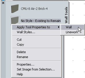
- One last item on the override method: If you expect to use many different wall styles for existing-to-remain walls and do not want to create multiple tools for each override condition you need, you can create a “generic” wall tool with the override attached but no style or style location specified.

 You can use this tool to start the WallAdd command with the override, then select the desired style on the Properties palette, or draw one or more walls with the “normal” wall tool[s], then right-click on the “generic existing-to-remain” tool and choose Apply Tool Properties to > Wall from the context menu to move the wall[s] to the A-Wall-E layer.



The next and final installment will cover setting up and assigning a new layer key in a wall tool.
February 04, 2006
Part 1 of 3: Placing Walls on a Layer Other Than A-Wall...
… or A210G7, A-Wall-G, 300_Waende, A_Walls, ADT_Waende, or whatever layer the Layer Key Style you are using has mapped to the WALL Layer Key. There are two cases here – in the first, you want all walls placed on the same layer, but want the layer name and/or layer attributes to be different that what you are getting. In the second, you want to keep the current wall layer for most walls, but have some that you want on a different layer.
CAUTION: If you are just experimenting, make the changes to a local file. Do not change the office-standard settings in your Auto-Import file unless you have the authority to make changes for your office.
This all started out as a single article, but grew in length to the point where I thought it best to split it up into three, more manageable segments. These tutorials, and their images, were created using Autodesk Architectural Desktop 2006. The procedures noted should apply to the 2004 and 2005 releases as well, although I did not run through them in those versions to see if there were any minor differences in behavior.
Changing the Layer Assigned to A Layer Key
The first case is fairly straightforward. The first thing you would want to look at is whether you are using the correct Layer Key Style. Autodesk Architectural Desktop ships with several Layer Standards, each of which has an associated Layer Key Style.
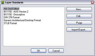
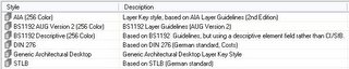
You can find these in the AecLayerStd.dwg file, which is located in the C:\Documents and Settings\All Users\Application Data\Autodesk\ADT 2006\enu\Layers folder if you use the default locations for content. The location for your setup may be different; check with your CAD Manager. Take a look at the various standards and find the one that most closely matches the layering you use. Setting up an entirely new Layer Standard is beyond the scope of this article; I will assume that one of the out-of-the-box Layer Standards and its associated Layer Key Style is close to what you need, but you want to change the layer name for the WALL key. Use the Style Manager to make a copy of the Layer Key Style and give it a different name, then edit that style and, on the Keys tab, you can change the name and layer settings for the WALL layer key, and others, as well.
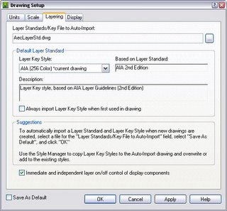
Once you have the Layer Key Style set up the way you want in a local file on your machine, you may decide that you would like that to be your [or your office’s] standard Layer Key Style, to be used in all drawings. You will want to copy your new Layer Key Style to the AecLayerStd.dwg, or whatever file you have set up as your Auto-Import file for Layer Standard/Layer Key on the Layering tab of the Drawing Setup dialog. If you are not going to use one of the out-of-the-box Layer Key Styles “as is”, I would recommend setting up your own, separate file for holding your layer standards, to make it easy to back up and migrate to later releases. Your custom file can be in the same folder as the AecLayerStd.dwg, just point to that file as your Auto-Import file on the Layering tab, then select your new Layer Key Style as the Default Layer Standard. If you want that to be the default setting for future drawings opened on that computer, check the Save As Default toggle in the lower left before clicking OK. [You may want to check the settings on the Units and Scale tabs, to make certain they are set to your desired default values before clicking OK.]
Click on any image to see a larger version. Stay tuned for the next installment, which will cover setting up a wall tool with a Layer Key Override.
CAUTION: If you are just experimenting, make the changes to a local file. Do not change the office-standard settings in your Auto-Import file unless you have the authority to make changes for your office.
This all started out as a single article, but grew in length to the point where I thought it best to split it up into three, more manageable segments. These tutorials, and their images, were created using Autodesk Architectural Desktop 2006. The procedures noted should apply to the 2004 and 2005 releases as well, although I did not run through them in those versions to see if there were any minor differences in behavior.
Changing the Layer Assigned to A Layer Key
The first case is fairly straightforward. The first thing you would want to look at is whether you are using the correct Layer Key Style. Autodesk Architectural Desktop ships with several Layer Standards, each of which has an associated Layer Key Style.


You can find these in the AecLayerStd.dwg file, which is located in the C:\Documents and Settings\All Users\Application Data\Autodesk\ADT 2006\enu\Layers folder if you use the default locations for content. The location for your setup may be different; check with your CAD Manager. Take a look at the various standards and find the one that most closely matches the layering you use. Setting up an entirely new Layer Standard is beyond the scope of this article; I will assume that one of the out-of-the-box Layer Standards and its associated Layer Key Style is close to what you need, but you want to change the layer name for the WALL key. Use the Style Manager to make a copy of the Layer Key Style and give it a different name, then edit that style and, on the Keys tab, you can change the name and layer settings for the WALL layer key, and others, as well.

Once you have the Layer Key Style set up the way you want in a local file on your machine, you may decide that you would like that to be your [or your office’s] standard Layer Key Style, to be used in all drawings. You will want to copy your new Layer Key Style to the AecLayerStd.dwg, or whatever file you have set up as your Auto-Import file for Layer Standard/Layer Key on the Layering tab of the Drawing Setup dialog. If you are not going to use one of the out-of-the-box Layer Key Styles “as is”, I would recommend setting up your own, separate file for holding your layer standards, to make it easy to back up and migrate to later releases. Your custom file can be in the same folder as the AecLayerStd.dwg, just point to that file as your Auto-Import file on the Layering tab, then select your new Layer Key Style as the Default Layer Standard. If you want that to be the default setting for future drawings opened on that computer, check the Save As Default toggle in the lower left before clicking OK. [You may want to check the settings on the Units and Scale tabs, to make certain they are set to your desired default values before clicking OK.]

Click on any image to see a larger version. Stay tuned for the next installment, which will cover setting up a wall tool with a Layer Key Override.
February 03, 2006
Underline in Tag But Not in Schedule II
For anyone intrigued by the Underline in Tag But Not in Schedule post I made back in December of last year, but who is alergic to formula properties, fear not, you too can do this without having to break out in hives.
While revisiting this idea this evening, it occurred to me that since all the formula in my sample file was doing was adding a fixed string - "%%u" - as a prefix to a manual property value, another and - it pains me to say this - even better solution would be to use a Property Data Format to add the prefix. Here's what you need to do:
Be certain to keep the original Property Data Format assigned to the room name column in your Schedule Table Style, so that the underline does not appear there. If you create a new Schedule Table Style and include your room name property in it, the default Property Data Format that will be applied will be your new one, with the underline prefix, so remember to change it back to the non-underlined version.
12/04/2015 UPDATE: Refer to this post for the revised method for doing this in later releases where %%u does not generate an underline.
While revisiting this idea this evening, it occurred to me that since all the formula in my sample file was doing was adding a fixed string - "%%u" - as a prefix to a manual property value, another and - it pains me to say this - even better solution would be to use a Property Data Format to add the prefix. Here's what you need to do:
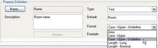
- Determine what Property Data Format the manual property or properties [if you use a multi-line tag; if you do not, read more about that topic here and here] into which you enter your room names is/are using. The out-of-the-box RoomObjects:Name property uses the Case - Upper Property Data Format, so I will use that for my example here.
- In the Style Manager, make a copy of the Property Data Format used by your room name property and rename it. I copied the Case - Upper Property Data Format and renamed it to Case - Upper - Underlined, and changed the description as shown below.
- On the Definition tab, enter "%%u", without the quotation marks, in the Prefix edit box, as shown below. That's all that is needed here!
- The last step is to edit the Property Set Definition that holds your room name property or properties and apply the new Property Data Format to it or them.

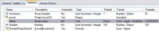
Out-Of-The-Box RoomObjects Property Set Defintion

General Tab, Case - Upper - Underline Property Data Format
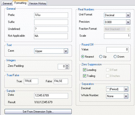
Definition Tab, Case - Upper - Underline Property Data Format

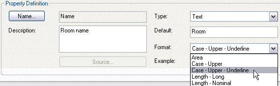
Case - Upper - Underline Property Data Format Assigned to RoomObjects:Name Property
Be certain to keep the original Property Data Format assigned to the room name column in your Schedule Table Style, so that the underline does not appear there. If you create a new Schedule Table Style and include your room name property in it, the default Property Data Format that will be applied will be your new one, with the underline prefix, so remember to change it back to the non-underlined version.
12/04/2015 UPDATE: Refer to this post for the revised method for doing this in later releases where %%u does not generate an underline.
Subscribe to:
Posts (Atom)