July 28, 2007

AutoCAD Architecture 2008 as AutoCAD

Although I rarely use the option, as I was installing AutoCAD® Architecture 2008 the other evening, I thought I was carefully making my way through the installation process and was surprised that there was not an unchecked toggle somewhere to add a desktop icon to run the program as AutoCAD®. I went back to modify the installation and still could not find that option, which had been there in the last few releases.

I was not too worried, having remembered that Matt Dillon had posted an article in his blog giving a method of creating such a shortcut without the need to go into the installation program. I opened up the program and after getting through the authorization process, opened up the Options dialog to begin making my usual changes to the out-of-the-box settings. While there, I noticed that a profile called "AutoCAD" had been created and found that profile was set up to run AutoCAD Architecture (ACD-A) "as AutoCAD". (And, yes, I did install all of the content options. Someday when I have some "extra" time, I will see whether there is any cool stuff in the content for countries other than the US.)

Rather than creating a shortcut that calls a previously undefined profile, as Matt suggested for the 2007 release, I chose to make use of the AutoCAD profile that was already there. The following outlines what I did. The first step was to find the icon of the shortcut I would normally use to start ACD-A 2008, right click, copy and then paste a copy on the desktop.
I then right clicked on the copied shortcut and selected Properties from the context menu. On the Shortcut tab, in the Target edit box, after the "/p" switch, I changed the name of the profile to be used when launching ACD-A to "AutoCAD".Then, since my desktop has quite a few ADT/ACD-A shortcuts, I edited the comment, which is the text that appears in the tool tip when hovering over a desktop shortcut, to reflect the function of this shortcut, as shown in the image below.
I also wanted to give this shortcut a distinctive icon, one my aging eyes would have no trouble distinguishing, so I selected the Change Icon... button, which opened a "Change Icon" dialog showing the current icon as the only choice. A click on the Browse... button in that dialog opened another "Change Icon" dialog that would allow selecting a different source file for the icon, starting in the folder in which the current icon's source file was located.Fortunately, the vanilla AutoCAD icon was also in that folder, and I chose that file and accepted that as the new icon.

The final step was to select the General tab and change the name of the shortcut, as seen below.I chose OK to dismiss the Properties dialog and I now have a desktop shortcut that will launch ACD-A 2008 as AutoCAD.

July 25, 2007

Pasting Formulas

Perhaps you have found the code for a formula property in a posting in an Autodesk Discussion Group or an AUGI Forum, and you wanted to add that formula to a Property Set Definition of your own. Someone else has already done all of the typing - why not just cut and paste the code and move on to your next task? Even if you already had - or just created - all of the other properties referenced by the sample code, you will find that cutting and pasting code from another source does not work. That is because property references have to be created by selecting them from the pane below the formula editing pane; you can not simply type in the name of the property, enclosed in square brackets: [MyPropertyReference]. Cut and paste will not work even if the source is another formula property, that has working property references!
The image above shows a formula property being edited, with text cut from Notepad and pasted into the edit pane. As you can see, the property references (text enclosed in square brackets) do not have the tell-tale gray background of a working property reference. (For ADT 2004 and 2005, the working property references appear in bold type.) After pasting, you could individually highlight each property reference and then double click on the corresponding property in the lower pane to replace the text with a working reference. In my simple example, that would only require three operations and would not be all that onerous. But for a more complex formula, there could be many more references, and the chore more tedious.

Fortunately, there is an alternative. You will need to scan through the code you intend to paste and identify all of the property references, but you would have to do that anyway, to make certain that all of those properties already existed. Keep a count of how many times each property is referenced. (If any one property is referenced more than two times, you may want to consider setting a variable to the value of that property up front, then using the variable in lieu of reading in the value multiple times.) As shown in the image below, add the property references in the code you intend to paste, one reference for each reference in the code, by double-clicking on the corresponding property in the lower pane. The sample code references the [HeightOverride] property twice and the [Height] property once, so that is what was added. Note the gray background behind the property references.
Now position the cursor before/above the property references you added. I like to throw a blank line or two before the references to be certain I am above them, and to make the final cleanup that much easier. Paste your code into the edit window and "presto-chango" - the code reference text you pasted in is now magically transformed into working code references, and the code references added prior to pasting are now plain text, as seen below.
All that remains is to highlight the extra lines and now useless text at the end of the formula and delete it.
Note: If the names of the properties in the code to be pasted are different from the equivalent properties in your Property Sets, you will need to paste the code to Notepad or a similar program and edit the name text to match your names before pasting it into the formula property, or this technique will not work.

July 01, 2007

Anchor Property Sample

In response to a question in the Schedule PSD thread in the AutoCAD Architecture 2008 Discussion Group, I posted a file done in ADT 2007 that demonstrates that an Anchor property can be used in a Property Set Definition attached to to a Window object to read in property data from the Wall object and use that to calculate the necessary window opening.

Two different options are given, one that assumes a style-naming convention that has the name of all stud wall styles starting with the letters "stud", and another that assumes that a manual property attached to the wall style contains the string "STUD" for all stud walls. The formulas associated with each method pass through the value of the automatic WidthUnformatted property for stud walls and add 3" to the width for all other wall types.

Use of a Anchor property, introduced in the 2007 release, makes this task much easier. Previous releases would have required a formula property to dig through the drawing database, to find the associated value.

June 17, 2007

Free Webcast - ACA Details


Steve Bennett, of LA CAD and tireless AUGI volunteer, is offering a free, one-hour webcast on Wednesday, June 20, 2007, titled Utilizing the Detail Engine in AutoCAD Architecture. See the details and find a link to the registration site in this article in his blog.

7/7/2007 Update: Steve is offering another webcast, this time on Project Management, on Wednesday, July 25, 2007. Get the details and a link to the registration site here.

June 16, 2007

Rounded Values and the Quantity Column

Many times you may have objects and associated data that you would like to document in a Schedule Table, but there are large numbers of "identical" objects - all the data in each objects row is the same - and you really do not need to show each line. This is just the situation that the quantity column was meant to handle - check the box on the Columns tab when creating or editing your Schedule Table Style to add a Quantity column, as shown in the image below.With a quantity column in your schedule table, all identical rows will "collapse" into a single row, with the total number of objects represented listed in the quantity column. If you do not want to display the actual quantity, simply hide the quantity column.

An interesting question came up in this thread in the Autodesk Architectural Desktop 2007 & Prior Discussion Group. The images in this blog post were taken from the ADT 2006 drawing file I posted in reply. The goal was to list spaces and their areas in a schedule table, using a quantity column to collapse spaces of the same type and area onto one line. Unfortunately, there were slight differences in the actual areas of the spaces, such as those in my sample file, as illustrated by the schedule table below. I created an "unformatted" automatic property to which I assigned a Property Data Format that is a copy of the Standard Property Data Format, with the precision set to eight decimal places.There are two different types of spaces: offices, at a nominal 100 square feet, and conference rooms, at a nominal 150 square feet. Intentional (in my case) stretching of the spaces by varying small amounts resulted in the slightly different areas shown, and preventing any lines from collapsing. Given the obviously different values, this is not surprising.

The discussion group poster noted that he had created a Property Data Format for his area properties that rounded the values to the nearest whole number, but this still was not allowing the rows to collapse, despite the apparently identical values. As shown below, I was able to reproduce that in my sample file. ADT is using the raw automatic property value, before the application of the Property Data Format, to determine whether rows are identical, as can be seen in the schedule table shown below.
Fortunately, there is a way to achieve the desired result, other than insisting on precise drafting. And while that is something of a pet peeve of mine, there certainly could be situations where there are legitimate small variations in a given value, that disappear when rounded to the desired accuracy for reporting the value. I can think of two ways to achieve the desired result, both of which involve the use of a formula property. Which works best for you will depend upon the specifics of your situation.

The first formula uses the unformatted automatic property and applies the Round function to get the desired precision, as seen below. For whole number precision, the Fix function may also work, although that will simply truncate any fractional amount, rather than round it.The advantage of using an unformatted property to get a numeric value, then applying the Round function in a formula property is that you can control the desired precision, and, with a little math, can even get a precision greater than whole number. For example, if you wanted to have the area value rounded to the nearest 50 square feet, you could do something like this:
Round( [NetAreaUnformatted]/50, 0 ) * 50
By dividing the value by 50, rounding, then multiplying the value by 50, you will get the value, rounded to the nearest 50. One thing to note for the Round function is that if the value of the digit beyond the one being rounded is exactly 5, the digit being rounded will round up if the digit is odd and down if the digit is even (that is, the result will always be an even digit). The results of using that formula in the schedule table can be seen below - the values for all four offices and all four conference rooms are now the same, so they collapse onto two lines, one for each type.
The second formula assumes that you can achieve the desired rounding with a Property Data Format, and simply takes the formatted version of the automatic property and passes it through the formula, enclosed in double quotation marks, to convert it to a string value, like this:
"[NetArea]"
Since the Property Data Format made the displayed values for each space type the same, the string will be the same, and the rows will collapse, as seen in the image below.
If you are interested, you can download the sample file I posted to the thread and take a look at the formulas "live".

June 15, 2007

AU 2007

Having attended three of the last four Autodesk Universities - I missed the 2005 edition in Orlando - I can attest to the fantastic opportunities to learn from and network with the best of the best. Even if you could afford to have Matt Dillon or Paul Aubin fly in and give you three-and-one-half days of one-on-one training, you would still miss out on all of the informal learning opportunities and the chance to meet fellow users, any one of whom might have a solution to an issue that has been giving you problems. Not to mention being able to "corner" members of the AutoCAD® Architecture development team, and provide some direct feedback.

If were thinking about going this year, but you have not yet started laying the groundwork, there is no better time than the present to start. Registration opens in "August", according to the Autodesk AU website. That is likely to be early in August, going by past years. If you need to make the case to your employer or a spouse, you will want to do so well before October 8, when the fees go up $500. Many of the more popular classes may be filled by that time, anyway.

If you need an additional incentive, and were hoping to be able to take a class that goes beyond the basics of the ACA Schedule feature, I am pleased to announce that my class proposal titled Get Fully Equipped in AutoCAD Architecture (90-minute class) has been accepted. I will be presenting a method of creating and scheduling equipment that I have used for several health care projects and which could easily be used on laboratory projects or adapted to any other project type where you need to show equipment or furniture in plan, with identifying tags and then create a schedule to list those items and related data. If that sounds interesting to you, and you are going to AU this year, I would appreciate you taking this class into consideration when selecting your classes.

If you are looking for a course that covers the basics of the ACA Schedule feature, Matt Dillon will be presenting Schedule Anything in AutoCAD Architecture or AutoCAD MEP in a 3 1/2 hour tutorial. If you have never taken Matt's Schedule Anything class before and are looking to master the basics of the Schedule feature, I can assure you that it will be well worth your time.

I do not know where on the schedule either of these classes fall at this time, but I hope that Matt's class is offered first, so that anyone wanting to take both, but who would benefit most by learning about the overall feature first, can do so.

June 02, 2007

ACA/ADT Layer LISP Functions

10/30/2014 - Updated to include ACA 2015
06/30/2013 - Updated to include ACA 2013 and 2014.
04/03/2011 - Updated to include ACA 2012.
01/27/2010 - Updated to include ACA 2008 - 2011!

AutoCAD® Architecture (ACA) and Autodesk® Architectural Desktop (ADT) ship with an ARX file that contains LISP functions that work with Layer Standards and Layer Keys. Mark Webb of Autodesk posted a synopsis of the LISP functions that were available in the AecLMgrLISP40.arx file that accompanied ADT 2004; you can obtain that synopsis in this thread in the AutoCAD Architecture Customization Discussion Group. Look for my repost on May 8, 2007.

Note that the name of the ARX file changes, depending upon the version you are using.
ADT 2004 - AecLMgrLisp40.arx
ADT 2005 - AecLMgrLisp45.arx
ADT 2006 - AecLMgrLisp47.arx
ADT 2007 - AecLMgrLisp50.arx
ACA 2008 through ACA 2015 - AecLMgrLisp.arx

ADT 3.3 included an ARX file called aeclayermanagerui30.arx; if memory serves, not all of the LISP functions listed in the synopsis noted above are present in that version.

Here is some sample code for loading the proper ARX function, based on the value of the ACADVER system variable. It supports ADT3.3 through ACA 2015.
(setq sacdvr (getvar "ACADVER"))
;; ARXload proper ARX function:
(cond ; cond A.
((= "15.06" sacdvr)
;; ARXload ADT3.3 function:
(if (not (member "aeclayermanagerui30.arx" (arx)))
; If the ARX file is not currently loaded...
(progn ; ...do the following:
(prompt "\nARXloading \"aeclayermanagerui30.arx\". ")
; Display prompt noting file to be loaded.
(if (arxload "aeclayermanagerui30.arx" nil)
; If ARX file loads successfully...
(setq flag T) ; ...set flag to T.
(prompt "\n; error: ARXLOAD failed")
; ...else display prompt and return nil.
) ;_ End if.
) ;_ End progn.
(setq flag T) ; ...else already loaded, set flag to T.
) ;_ End if.
) ;_ End condition A1.
((= "16.0" sacdvr)
;; ARXload ADT2004 function:
(if (not (member "aeclmgrlisp40.arx" (arx)))
; If the ARX file is not currently loaded...
(progn ; ...do the following:
(prompt "\nARXloading \"aeclmgrlisp40.arx\". ")
; Display prompt noting file to be loaded.
(if (arxload "aeclmgrlisp40.arx" nil)
; If ARX file loads successfully...
(setq flag T) ; ...set flag to T.
(prompt "\n; error: ARXLOAD failed")
; ...else display prompt and return nil.
) ;_ End if.
) ;_ End progn.
(setq flag T) ; ...else already loaded, set flag to T.
) ;_ End if.
) ;_ End condition A2.
((= 16.1 (atof sacdvr))
;; ARXload ADT2005 function:
(if (not (member "aeclmgrlisp45.arx" (arx)))
; If the ARX file is not currently loaded...
(progn ; ...do the following:
(prompt "\nARXloading \"aeclmgrlisp45.arx\". ")
; Display prompt noting file to be loaded.
(if (arxload "aeclmgrlisp45.arx" nil)
; If ARX file loads successfully...
(setq flag T) ; ...set flag to T.
(prompt "\n; error: ARXLOAD failed")
; ...else display prompt and return nil.
) ;_ End if.
) ;_ End progn.
(setq flag T) ; ...else already loaded, set flag to T.
) ;_ End if.
) ;_ End condition A3.
((= 16.2 (atof sacdvr))
;; ARXload ADT2006 function:
(if (not (member "aeclmgrlisp47.arx" (arx)))
; If the ARX file is not currently loaded...
(progn ; ...do the following:
(prompt "\nARXloading \"aeclmgrlisp47.arx\". ")
; Display prompt noting file to be loaded.
(if (arxload "aeclmgrlisp47.arx" nil)
; If ARX file loads successfully...
(setq flag T) ; ...set flag to T.
(prompt "\n; error: ARXLOAD failed")
; ...else display prompt and return nil.
) ;_ End if.
) ;_ End progn.
(setq flag T) ; ...else already loaded, set flag to T.
) ;_ End if.
) ;_ End condition A4.
((= 17.0 (atof sacdvr))
;; ARXload ADT2007 function:
(if (not (member "aeclmgrlisp50.arx" (arx)))
; If the ARX file is not currently loaded...
(progn ; ...do the following:
(prompt "\nARXloading \"aeclmgrlisp50.arx\". ")
; Display prompt noting file to be loaded.
(if (arxload "aeclmgrlisp50.arx" nil)
; If ARX file loads successfully...
(setq flag T) ; ...set flag to T.
(prompt "\n; error: ARXLOAD failed")
; ...else display prompt and return nil.
) ;_ End if.
) ;_ End progn.
(setq flag T) ; ...else already loaded, set flag to T.
) ;_ End if.
) ;_ End condition A5.
((or
(= 17.1 (atof sacdvr))
(= 17.2 (atof sacdvr))
(= 18.0 (atof sacdvr))
(= 18.1 (atof sacdvr))
(= 18.2 (atof sacdvr))
(= 19.0 (atof sacdvr))
(= 19.1 (atof sacdvr))
(= 20.0 (atof sacdvr))
) ;_ End or.
;; ARXload ACA 2008 through 2015 function:
(if (not (member "aeclmgrlisp.arx" (arx)))
; If the ARX file is not currently loaded...
(progn ; ...do the following:
(prompt "\nARXloading \"aeclmgrlisp.arx\". ")
; Display prompt noting file to be loaded.
(if (arxload "aeclmgrlisp.arx" nil)
; If ARX file loads successfully...
(setq flag T) ; ...set flag to T.
(prompt "\n; error: ARXLOAD failed")
; ...else display prompt and return nil.
) ;_ End if.
) ;_ End progn.
(setq flag T) ; ...else already loaded, set flag to T.
) ;_ End if.
) ;_ End condition A6.
(T
(alert
(strcat
"Unsupported version of AutoCAD is running."
"\nACADVER = " sacdvr "."
"\n\nPlease notify Computer Services."
) ;_ End strcat.
) ;_ End alert.
nil ; Return nil.
) ;_ End condition A7.
) ;_ End cond A.

Note that after running that code, the LISP variable flag will be set to T (true) if the ARX file was already loaded or was successfully loaded and will be set to nil if the ARX file failed to load. Your subsequent code may want to test that value before trying to use one of the LISP routines defined by the ARX file.

One function that many users will find useful is AecGenerateLayerKey function, which takes one argument, the name of a Layer Key as a quoted string. If a layer of that name does not exist in the drawing file, it will be created, using the parameters specified in the current Layer Key Style, and the layer name returned. If a layer of that name already exists, the layer name is returned, but no changes are made to the layer's properties (color, linetype, etc.), even if they do not agree with those set in the Layer Key Style. That is consistent with the way a Layer Key works when called by an ACA/ADT object create command, or by AEC Content. If the specified Layer Key does not exist in the current Layer Key Style, the Layer Key name is returned as a quoted string. No other action is taken, if you want that layer set current, trap the return value, test to see if it is nil and, if not, use the CLAYER system variable or the LAYER command in your routine to set that layer current. This function allows you to add Layer Keying to any custom LISP routines you may have for things that AEC Content alone can not do easily, or which you wrote long before using ADT/ACA.

A pair of functions I found useful when customizing a Layer Standard for my firm were the AecLayerSaveStdAsText and AecLayerLoadStdAsText functions. This allows you to export the contents of a Layer Standard as a formatted text file, open the text file in a text editor, like Notepad, carefully make edits - preserving the proper formatting, then reload the edited file as a Layer Standard in a drawing file. My firm's Layer Standard is based on the U.S. National CAD Standard, and I wanted to have all of the Minor fields available in both Minor1 and Minor2. Rather than enter each field twice in the editor available inside ADT or ACA, I was able to export the Layer Standard to a text file, copy all the Minor1 field values to Minor2 and then reload the text file. I believe I may have tweaked some of the other field values before reloading the file, as well. Much more efficient, and it avoided the possibility of typos when doing the same thing twice.

There are a number of other layer-related functions in the ARX file, for setting Layer Key Overrides, toggling Layer Key Overrides on and off, generating a list of Layer Keys and working with layer snapshots. Take a look at what is available, and make use of those that fit your needs.

May 26, 2007

Drawing Accurately

I can not stress enough the importance of drawing accurately when using Autodesk® Architectural Desktop, AutoCAD® Architecture, or even AutoCAD®, for that matter. Nearly all of my work is done in imperial units, and when creating "the model" (or just "drawing"), I generally keep my units set to Engineering (feet, inches and decimal inches) and the precision set to at least five decimal places, to avoid having small errors being masked by the rounding that takes place when using architectural units.

I often hear, "Why bother, it will not be built with that level of accuracy in the field and the precision on the dimensions is set to 1/8" anyway?" I understand that in the field, getting to within 1/4" of the design is a very good day, and that any given wall is not straight, nor are any two walls perpendicular or parallel. Your design needs to make allowances for construction tolerances, particularly when a more precise item, such as a factory produced object, is installed adjacent to a less precise item, like a field-built wall. I would argue that you still want to draw accurately so that you know what dimension you "should" have, and then apply your tolerances to that.

One very important reason is that Autodesk Architectural Desktop/AutoCAD Architecture objects can do some strange things when they are not drawn precisely. (And, as Larry Bettes notes in the Discussion Group thread noted below, not only should the objects be drawn precisely, but you want to start from a point that is a whole number, or at least does not require all 16 of the significant figures available.) Another important reason is if you draw your model accurately, you can query the model for information and have a reasonable level of confidence that the information you get back is accurate. Is it just me, or are the very people who draw with the precision set to a large value or "eyeball" when placing a new object or moving an existing one ("Snaps, what are those?" "Keying in a distance takes too much time!") the very same people who think you can take that inaccurate model and blindly add dimensions and everything will be just fine? Perhaps the error between any two adjacent walls is small, and less than construction tolerances, but when you have a number of such inaccuracies added together, you can not always count on them cancelling each other out.

Here is one example of how small imprecisions can add up to sizable error. The total error in this example is small, but keep in mind the precision on the dimension strings is 1/64", and in one foot the error is already four times that. The images below are based on a file I created and posted to this thread in the Autodesk Architectural Desktop 2007 & Prior Discussion Group.

I did modify the dimension style to use the Arial text style and bumped the DIMSCALE up to 2 so that the numbers would be more easily seen in the screen captures.

I started with a dimension style that has its precision set to 1/64" and drew a dimension exactly 1'-0" long. As you can see in the image below, the Measurement property of the dimension indicates 1'-0.00000000".

Then I added eight dimensions, each of which displays 1 1/8" as the dimension value (no text overrides here, trust me).

Given this, you would expect a closing dimension to show 3", since 1'-0" - (8 * 1.125") = 3". But you would be wrong, as can be seen below.

How did the closing dimension end up being 3 1/16"? Simple: all eight of the 1 1/8" dimensions are identical, and as shown below, are NOT exactly 1.125", but are instead 1.1175". This makes each one just less than 1/128" shy of 1 1/8" (and therefore just over 1/128" more than 1 7/64"), so the value rounds up to the nearest 1/64", or 1 1/8". This gives the impression of 1/8" accuracy without the substance, and allows the closing dimension's measurement, 3.06000000, to be reported at 3 1/16".

So a series of small inaccuracies can add up to a significant one. And while the difference may still be relatively minor, the point is that by drawing inaccurately, you are allowing the person doing the layout on site to determine where any extra dimension goes or where any missing dimension is taken out. Nine times out of ten you may not care. But that tenth time, when the expensive piece of millwork does not fit, you will care, but it will be too late. If you work on a team with others who rely on the accuracy of your work to do their work, you may find that you care even sooner. With all of the tools at hand in Autodesk Architectural Desktop/AutoCAD Architecture, it really does not take that much additional effort to draw accurately, and the time you save chasing dimension strings that do not add up and dealing with layout issues in the field will more than make up for the extra effort. And you may see fewer wall cleanup issues, to boot!

May 10, 2007

Cycling Between Viewports in a Layout

Those of you who used Autodesk® Architectural Desktop prior to the introduction of the Customize User Interface (CUI) files in 2006 may recall that the menu file included an "accelerator" for the CTRL+R keystroke combination that would cycle between the viewports in a layout whose extents are at least partially visible on-screen. Those of you who have been using AutoCAD® for many years may also recall that the "original" accelerator was CTRL+V [or ^V in a menu macro], which got supplanted when Windows came along and made CTRL+V "paste".

The ability to cycle through the viewports can be handy when you have overlapping viewports and the program decides the one you want is "underneath" the one you do not want, and is essential if you have an "underneath" viewport that is entirely within the boundaries of another viewport. For whatever reason, the CTRL+R accelerator did not get incorporated into the ADT.cui file, so users of 2006 and later may find they no longer can cycle through viewports using CTRL+R. The good news is nothing else has been assigned to CTRL+R, and it is not difficult to add the CTRL+R functionality back.

In CUI files, the old accelerators are now called Shortcut Keys and are found under the Keyboard Shortcuts category of a given CUI. You can add Shortcut Keys to the main CUI or any partial CUIs you may have loaded; if you have a separate CUI for your company standard menu items or for your personal use, you may want to add the CTRL+R Shortcut Key there, to aid in migrating to future releases. The Help contains instructions for how to add a Shortcut Key, and there is even a video in the 2007 Help for those of you who are visually oriented. You can find this by navigating here: AutoCAD Help > Customization Guide > Customize the User Interface > Add Shortcut Keys and Temporary Overrides. In 2006, click on the Procedures tab, then select the "To create a shortcut key" link. In 2007, the video is on the "Add Shortcut Keys and Temporary Overrides" page.

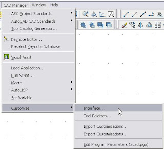
For those who have an allergic reaction to the Help, or who find the fact that the instructions are written around the ACAD.cui, not the ADT.cui too annoying to bear, the balance of this article covers the specifics of adding the ^V macro as a Shortcut Key and assigning the CTRL+R keystroke to it. The first thing you will need to do is open the Customize User Interface dialog. Type CUI at the Command: prompt. If you hate keyboarding and want to use a pulldown menu, you will not be able to use the Tools pulldown, as noted in the Help [unless you have added that from the ACAD.cui file]. If you have added the CAD Manager pulldown menu [Window > Pulldowns > CAD Manager Pulldown] you can start the CUI command from there, as shown below. [As always, you can view a full-size version of reduced size images by clicking on the image.]
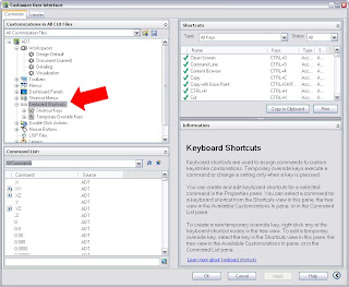
Set the Customize tab active, if it is not already current. The upper left pane of the Customize tab lists the CUI files that are loaded. You can choose to show all CUI files, or focus on one using the dropdown list at the top of the pane. Expand the CUI in which you want to add the CTRL+R Shortcut Key and then expand the Keyboard Shortcuts category, as shown below. You will not see the large red arrow, which I added to the image for emphasis.
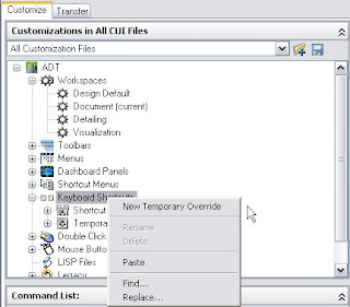
Here is a tip for those of you who have fully embraced the AutoCAD® Architecture/Autodesk Architectural Desktop mindset of right-clicking to do just about anything. In this case, it will not work. You can right click on either "Keyboard Shortcuts" or "Shortcut Keys" and a context menu will obediently appear, but there will not be an option to add a new Shortcut Key, as can be seen in the image below.
New Shortcut Keys are created by dragging the command you want from the Command List in the lower left pane of the CUI dialog and dropping it onto "Shortcut Keys" in the upper left pane. Fortunately for our example, there is alread a "command" in the Command List, named "CTRL+R", that has the ^V macro assigned to it, so we do not need to add a custom command to the list. Scroll down in the Command List list box until you see the "CTRL+R" command.
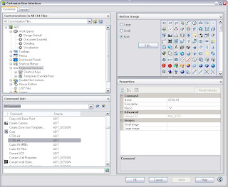
Left click on and then drag the "CTRL+R" command up to "Shortcut Keys" in the upper left pane and drop it there.
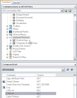
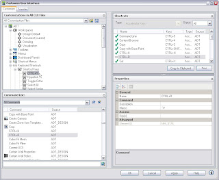
Expand the Shortcut Keys subcategory, if it did not do so automatically while you were dragging and dropping, and then find and select your new "CTRL+R" command on the list of commands. This will change the display on the right side of the Customize tab of the CUI dialog, displaying "Shortcuts" in the upper right pane, with a list of all of the Shortcut Keys commands, and "Properties" in the lower right pane. Since you selected "CTRL+R" command in the upper left pane, it is highlighted in the upper right pane and the Properties pane shows the properties for that command. Notice the horizontal bar in the left column in the Shortcuts pane, rather than the check mark that the other commands have. That is because a keystroke has not been assigned yet.
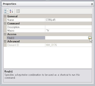
To assign a keystroke, click in the right column next to the "Key(s)" line in the Access category of the Properties pane. An ellipsis button will appear at the right side of that line; select it to open the Shortcut Keys dialog.
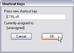
The Shortcut Keys dialog allows you to indicate what keystroke combination you want to assign to this command. Click in the edit box, if the focus is not already there, then press the "CTRL" and "R" keys at the same time, to enter "CTRL+R". The dialog will tell you what command is currently assigned to that keystroke combination, if any. If you are satisfied with the entry, select OK to return to the CUI dialog box.
You have now assigned a keystroke combination to the CTRL+R command, and the Shortcuts pane now shows a checkmark in the first column on that line, as well as the assigned keystroke combination in the Keys column. Select the Apply button to save this change to the CUI, if you have additional changes to make, or select OK to save the change and return to the drawing file.
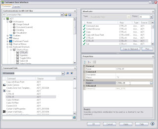
You should now find pressing CTRL+R when model space is active on a Layout with multiple viewports visible on screen will cycle through those viewports. You will want to back up the CUI file in which you made the change, to avoid having to do it again in the future, should you ever "lose" that file.

April 27, 2007

File Format Change in AMEP 2008

Here is a heads up for anyone using AutoCAD® MEP or anyone who works with those who do. While AutoCAD® Architecture 2008 uses the same file format as its predecessor, Autodesk® Architectural Desktop 2007, AutoCAD MEP 2008 does NOT use the same file format as Autodesk® Building Systems 2007. Apparently, AutoCAD MEP 2008 files will not be compatible with the 2007 releases.

While the Object Enabler site does not list anything for the 2008 products, an Object Enabler for AutoCAD MEP 2008 is available here. The site lists it being applicable only to the 2008 release of Autodesk products. The Readme does not indicate that installing the enabler would affect the format of any non-AutoCAD MEP files that were opened.