February 09, 2009
2010 Product Launch Press Materials
If you are curious about what the 2010 release holds for AutoCAD Architecture (and other Autodesk products), you may want to download one or more of the press materials ZIP files or take a look at the video archives of the virtual press conferences here.


January 31, 2009
Searching for Files with a Specific External Reference
If you have ever wanted to know all of the files that include a particular external reference, but had to resort to opening every possible file and manually check it, you will want to read Lynn Allen's post on using DesignCenter to search files for external references.
January 01, 2009
AU Online Abandons Single Sign-in
Less than four months after launching the "single sign-in" for all Autodesk Websites, the recent relaunch of the AU Online site has resulted in that part of the Autodesk web presence abandoning the single sign-in.
I used the feedback link on the AU Online site to question why the single sign-in had been abandoned. After the first reply indicated that the single sign-in was still valid for AU Online, I provided a more detailed description of what that meant (one sign-in for all sites/once signed in at one, moving to any other does not require signing in again), I was told that the single sign-in was removed due to a large amount of attendee feedback against it.
While I suppose I should applaud Autodesk for listening to the users, I have to question who would be against this? I would emphasize that there is a difference between being against the way it was implemented and being against the concept in general.
Yes, I was annoyed by the way it was implemented and by the spotty initial performance, complicated by rolling out a new format for the web-based Discussion Groups at the same time. Yes, I miss my old five-character password, now bloated to eight characters with at least one upper case letter and one numeral, because each additional character geometrically increases the probability that I will mistype the password. But with the single sign-in system, at least I could sign in once and visit the Discussion Groups, AU Online and the Subscription site. Now, I still have the eight-character password AND I have to sign in separately at AU Online.
So the question remains - who would want to sign in multiple times? Disconnecting the AU Online site from the single sign-in did not resolve any of the initial problems I had with the implementation - were there any other, ongoing issues? If anyone had a problem with the whole concept, what prevented them from simply signing out when leaving one site, then sign back in on the next?
I have to think that the real issue here was one of either not having time or not wanting to expend the effort to integrate the new AU Online site with the single sign-in, rather than responding to meaningful user feedback.
I used the feedback link on the AU Online site to question why the single sign-in had been abandoned. After the first reply indicated that the single sign-in was still valid for AU Online, I provided a more detailed description of what that meant (one sign-in for all sites/once signed in at one, moving to any other does not require signing in again), I was told that the single sign-in was removed due to a large amount of attendee feedback against it.
While I suppose I should applaud Autodesk for listening to the users, I have to question who would be against this? I would emphasize that there is a difference between being against the way it was implemented and being against the concept in general.
Yes, I was annoyed by the way it was implemented and by the spotty initial performance, complicated by rolling out a new format for the web-based Discussion Groups at the same time. Yes, I miss my old five-character password, now bloated to eight characters with at least one upper case letter and one numeral, because each additional character geometrically increases the probability that I will mistype the password. But with the single sign-in system, at least I could sign in once and visit the Discussion Groups, AU Online and the Subscription site. Now, I still have the eight-character password AND I have to sign in separately at AU Online.
So the question remains - who would want to sign in multiple times? Disconnecting the AU Online site from the single sign-in did not resolve any of the initial problems I had with the implementation - were there any other, ongoing issues? If anyone had a problem with the whole concept, what prevented them from simply signing out when leaving one site, then sign back in on the next?
I have to think that the real issue here was one of either not having time or not wanting to expend the effort to integrate the new AU Online site with the single sign-in, rather than responding to meaningful user feedback.
December 19, 2008
Non-Project Door Tag Using Room Number with Prefix and/or Suffix
If you are not using the Drawing Management feature (Project Browser and Project Navigator), you can still have room-number-based door numbers, and even allow for an optional prefix and/or suffix. You may have to do a little bit of setup, and create a custom Schedule Tag (or edit a copy of one of the out-of-the-box Schedule Tags), but it is really not all that hard, and the only thing that the Drawing Management feature brings (other than pre-made content) is the ability to have the room number prefixed by the Level property, which is an automatic project property. I will assume that you have dealt with that issue and have a way to assign your desired room number to each Space in a property in an object-based Property Set that is attached to each Space.
Making that room number property available to a Door is as simple as adding a Location property to an object-based Property Set that "Applies To" Doors. Location properties are best placed in object-based Property Sets. You can add one to a style-based Property Set, but unless the object already has another Location property in an object-based Property Set attached to it, the "Location grip" will not be generated and the Location property will not work. The Location grip, as seen below, is a four-pointed-star-shaped grip, that can be moved independently of the Door to which it is attached, and which will retrieve the specified property value from the first Space it finds below itself.
You can call for a Location property to return the value of any property that is in a Property Set that "Applies To" to a Space or AEC Polygon. (If you are using 2006 or earlier, Location properties also work with Area objects.) The Property Set of the referenced property must be attached to the Space or AEC Polygon in order for the Location property to return a meaningful value.
A prefix or suffix can be added by providing a manual property of the desired type. You can then display this value in a separate attribute in a Schedule Tag, as the out-of-the-box project-based Door Schedule Tag does, or by using a formula property to concatenate the prefix, room number and suffix into a single property. I have posted a sample file demonstrating how this could be done to this thread in the Autodesk Architecture Discussion Group. The DoorObjects2 Property Set in that file Applies To Door and Door/Window Assembly objects, and has the properties seen below. (Click on any image to see a larger version; use your web browser's Back button to return here.) SpaceNumber is a Location property that retrieves the SpaceObjects2:Number property that holds the room number. DoorNumberPrefix and DoorNumberSuffix are two manual properties that allow the user to add a prefix and/or a suffix to the room number value to create the final door number. The default value for each is an empty string. DoorNumber is the property that generates that final door number; it is a formula property whose formula is shown below.
  The formula checks the value entered into the DoorNumberPrefix property and, if it is an empty string, sets the variable doornumber1 to an empty string. If the user has entered a prefix value, doornumber1 is set to that prefix value with a period added as a delimiter, to visually separate the prefix from the room number. That part is not necessary, but some sort of delimiter may be desired if the nature of the prefixes and room numbers that you might be using could make it hard to tell if there is a prefix or not.
The formula then does a similar thing with the DoorNumberSuffix property, setting the variable doornumber2 to an empty string if a suffix was not added or to the concatenation of a period followed by the DoorNumberSuffix value, if a value was entered. Finally, the RESULT of the formula property is the concatenation of the doornumber1 value, the room number (from the SpaceNumber property) and the doornumber3 value. If no prefix or suffix is specified, then the room number is the final result, as seen at the Door in Conf 1007 in the sample plan below. The other Doors have a prefix, a suffix or both added to the room number, with the period delimeter separating any non-empty prefix or suffix from the room number.
If you want to see this in action, download and unZIP the sample file attached to my reply in the above-linked Discussion Group thread and try it out for yourself. The file was created in AutoCAD Architecture 2008, so you would need 2007 or later to be able to open the file.
Making that room number property available to a Door is as simple as adding a Location property to an object-based Property Set that "Applies To" Doors. Location properties are best placed in object-based Property Sets. You can add one to a style-based Property Set, but unless the object already has another Location property in an object-based Property Set attached to it, the "Location grip" will not be generated and the Location property will not work. The Location grip, as seen below,
 is a four-pointed-star-shaped grip, that can be moved independently of the Door to which it is attached, and which will retrieve the specified property value from the first Space it finds below itself.
You can call for a Location property to return the value of any property that is in a Property Set that "Applies To" to a Space or AEC Polygon. (If you are using 2006 or earlier, Location properties also work with Area objects.)
 The Property Set of the referenced property must be attached to the Space or AEC Polygon in order for the Location property to return a meaningful value.
A prefix or suffix can be added by providing a manual property of the desired type. You can then display this value in a separate attribute in a Schedule Tag, as the out-of-the-box project-based Door Schedule Tag does, or by using a formula property to concatenate the prefix, room number and suffix into a single property. I have posted a sample file demonstrating how this could be done to this thread in the Autodesk Architecture Discussion Group. The DoorObjects2 Property Set in that file Applies To Door and Door/Window Assembly objects, and has the properties seen below. (Click on any image to see a larger version; use your web browser's Back button to return here.)
 SpaceNumber is a Location property that retrieves the SpaceObjects2:Number property that holds the room number. DoorNumberPrefix and DoorNumberSuffix are two manual properties that allow the user to add a prefix and/or a suffix to the room number value to create the final door number. The default value for each is an empty string. DoorNumber is the property that generates that final door number; it is a formula property whose formula is shown below.
  The formula checks the value entered into the DoorNumberPrefix property and, if it is an empty string, sets the variable doornumber1 to an empty string. If the user has entered a prefix value, doornumber1 is set to that prefix value with a period added as a delimiter, to visually separate the prefix from the room number. That part is not necessary, but some sort of delimiter may be desired if the nature of the prefixes and room numbers that you might be using could make it hard to tell if there is a prefix or not.
The formula then does a similar thing with the DoorNumberSuffix property, setting the variable doornumber2 to an empty string if a suffix was not added or to the concatenation of a period followed by the DoorNumberSuffix value, if a value was entered. Finally, the RESULT of the formula property is the concatenation of the doornumber1 value, the room number (from the SpaceNumber property) and the doornumber3 value. If no prefix or suffix is specified, then the room number is the final result, as seen at the Door in Conf 1007 in the sample plan below. The other Doors have a prefix, a suffix or both added to the room number, with the period delimeter separating any non-empty prefix or suffix from the room number.

If you want to see this in action, download and unZIP the sample file attached to my reply in the above-linked Discussion Group thread and try it out for yourself. The file was created in AutoCAD Architecture 2008, so you would need 2007 or later to be able to open the file.
November 15, 2008
Creating Annotative Tags in AutoCAD® Archtitecture
Annotative content, first added in the 2008 release, is a great feature, particulary for things like Schedule Tags – no more messing around with multiple view blocks and adding Display Representations/Display Representation Sets/Display Configurations to get a single tag to display at multiple scales. But, as you may have discovered, it can make creating a new tag, or even modifying an old one, and getting things the right size something of a challenge. Part of the confusion stems from the fact that AutoCAD and AutoCAD Architecture treat annotative content differently. AutoCAD will insert an annotative block using the current drawing scale’s scale factor to determine the final size; AutoCAD Architecture will use annotation scaling (as it did before AutoCAD added the annotative feature), a combination of the current drawing scale’s scale factor and the annotation plot size (specified on the Scale tab of the Drawing Setup dialog). Here is a method I use to make certain I get the Schedule Tag size I want, and it works whether I am drawing the graphics from scratch, inserting an existing Schedule Tag Multi-View Block and exploding it or directly inserting an existing view block and exploding it. It also works whether I use the Define Schedule Tag (AecDefineTag) or choose to build the Multi-View Block for my Schedule Tag manually.
Step 1: Set the Drawing Scale to 1’-0” = 1’=0” (or 1:1, for metric users) and the Annotation Plot Size to 1. In 2008, you can do both on the Scale tab of the Drawing Setup dialog. In 2009, you will need to set the Scale in the popup list on the Drawing Window Status Bar (or on the Application Status Bar, if you have the Drawing Window Status Bar turned off), since the Scale list on the Scale tab is only used to associate a Display Configuration with a scale, not to set the Drawing Scale.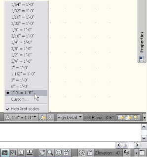
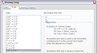
Step 2: Create the graphics for your view block(s), keeping in mind that one unit in the block will plot at the Annotation Plot Size in effect at plot time. So if you want the property datum displayed in a particular attribute to plot at the Annotation Plot Size, make the attribute definition or text placeholder (if you are using the Define Schedule Tag wizard) one unit high. You can scale attribute definitions/text place holders up or down from one unit to get larger or smaller text in the tag, if desired. Draw any other graphics to suit. If you plan to start with the graphics from an existing Multi-View Block, you can insert an instance of it now, and it will be scaled in accordance with one unit plotting at the Annotation Plot Size, since the effective scale factor in 1 (Drawing Scale of 1 x Annotation Plot Size of 1). If you prefer to insert the view block of the tag directly, that too will insert at the proper size (Drawing Scale Factor of 1). Make the desired changes to the exploded content, or draw the desired graphics from scratch.
Step 3, Option A: Fire up the Define Schedule Tag wizard, select your graphics, convert any placeholder labels that are meant to display properties to have a Type of Property and assign the desired Property Set and Property to each. TIP: I like to to follow the out-of-the-box naming convention of using the Multi-View Block name with “_P” appended to it for the view block. The wizard will assign the same name to both the Multi-View Block for the Schedule Tag and the view block definition. I find it easier to use the view block name in the dialog, and then rename the Multi-View Block Definition in the Style Manager after it is created. Once you have everything set the way you want in the dialog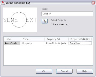 select the OK button, specify an insertion point for the Multi-View Block/view block, save the file and make a Tag tool by dragging the Multi-View Block to an editable tool palette. (For shared content, save the file as a source file in a location accessible to all, or copy the new Multi-View Block Definition to such a file, and then make the Tag tool from that file.) Set a Layer Key and make certain all of the other Properties of the Tag tool are as you desire, and you should be good to go. Reset the Annotation Plot Size back to your office standard, and set an appropriate Drawing Scale, and try out your new tag. It should come in at the expected size, and react to changes in Drawing Scale or Annotation Plot Size as expected.
Step 3, Option B: To use this option, you need to have attribute definitions with properly formatted attribute tags for each Property you want the Schedule Tag to show. Create an AutoCAD block definition for each view block you are going to assign to your tag. Fire up the Style Manager, create a new Multi-View Block Definition and add the view block(s) to the appropriate Display Representation(s) and then indicate the view directions for which each is to be visible. Exit Style Manager and save the file, or use Style Manager to copy the Multi-View Block Definition to a central source file and apply the changes. Create a Tag tool on an editable tool palette, set a Layer Key and make certain all of the other Properties of the Tag tool are as you desire, reset your Annnotation Plot Size and Drawing Scale and give it a try.
For a “simple” one-view-block Schedule Tag (as at least 90% of your tags will be, now that annotative content eliminates the need for multiple view blocks for multiple scales), Option A in Step 3 would be the way to go. Option B, on the other hand, may be useful if, for example, you have a space tag that needs to show different things for different drawing types – perhaps it shows the room name and area for schematic plans, room name and number for contract document floor plans and room name, number and ceiling height in reflected ceiling plans. Depending upon your workflow, it may be easier to have one tag that can do all of that than to have three separate tags. Of course, you could start out with Option A to get the first view block and the Multi-View Block set up, then add additional view blocks and adjust the Display Representations each block uses in the Multi-View Block as required.
Step 1: Set the Drawing Scale to 1’-0” = 1’=0” (or 1:1, for metric users) and the Annotation Plot Size to 1. In 2008, you can do both on the Scale tab of the Drawing Setup dialog. In 2009, you will need to set the Scale in the popup list on the Drawing Window Status Bar (or on the Application Status Bar, if you have the Drawing Window Status Bar turned off), since the Scale list on the Scale tab is only used to associate a Display Configuration with a scale, not to set the Drawing Scale.


Step 2: Create the graphics for your view block(s), keeping in mind that one unit in the block will plot at the Annotation Plot Size in effect at plot time. So if you want the property datum displayed in a particular attribute to plot at the Annotation Plot Size, make the attribute definition or text placeholder (if you are using the Define Schedule Tag wizard) one unit high. You can scale attribute definitions/text place holders up or down from one unit to get larger or smaller text in the tag, if desired. Draw any other graphics to suit. If you plan to start with the graphics from an existing Multi-View Block, you can insert an instance of it now, and it will be scaled in accordance with one unit plotting at the Annotation Plot Size, since the effective scale factor in 1 (Drawing Scale of 1 x Annotation Plot Size of 1). If you prefer to insert the view block of the tag directly, that too will insert at the proper size (Drawing Scale Factor of 1). Make the desired changes to the exploded content, or draw the desired graphics from scratch.
Step 3, Option A: Fire up the Define Schedule Tag wizard, select your graphics, convert any placeholder labels that are meant to display properties to have a Type of Property and assign the desired Property Set and Property to each. TIP: I like to to follow the out-of-the-box naming convention of using the Multi-View Block name with “_P” appended to it for the view block. The wizard will assign the same name to both the Multi-View Block for the Schedule Tag and the view block definition. I find it easier to use the view block name in the dialog, and then rename the Multi-View Block Definition in the Style Manager after it is created. Once you have everything set the way you want in the dialog
 select the OK button, specify an insertion point for the Multi-View Block/view block, save the file and make a Tag tool by dragging the Multi-View Block to an editable tool palette. (For shared content, save the file as a source file in a location accessible to all, or copy the new Multi-View Block Definition to such a file, and then make the Tag tool from that file.) Set a Layer Key and make certain all of the other Properties of the Tag tool are as you desire, and you should be good to go. Reset the Annotation Plot Size back to your office standard, and set an appropriate Drawing Scale, and try out your new tag. It should come in at the expected size, and react to changes in Drawing Scale or Annotation Plot Size as expected.
Step 3, Option B: To use this option, you need to have attribute definitions with properly formatted attribute tags for each Property you want the Schedule Tag to show. Create an AutoCAD block definition for each view block you are going to assign to your tag. Fire up the Style Manager, create a new Multi-View Block Definition and add the view block(s) to the appropriate Display Representation(s) and then indicate the view directions for which each is to be visible. Exit Style Manager and save the file, or use Style Manager to copy the Multi-View Block Definition to a central source file and apply the changes. Create a Tag tool on an editable tool palette, set a Layer Key and make certain all of the other Properties of the Tag tool are as you desire, reset your Annnotation Plot Size and Drawing Scale and give it a try.
For a “simple” one-view-block Schedule Tag (as at least 90% of your tags will be, now that annotative content eliminates the need for multiple view blocks for multiple scales), Option A in Step 3 would be the way to go. Option B, on the other hand, may be useful if, for example, you have a space tag that needs to show different things for different drawing types – perhaps it shows the room name and area for schematic plans, room name and number for contract document floor plans and room name, number and ceiling height in reflected ceiling plans. Depending upon your workflow, it may be easier to have one tag that can do all of that than to have three separate tags. Of course, you could start out with Option A to get the first view block and the Multi-View Block set up, then add additional view blocks and adjust the Display Representations each block uses in the Multi-View Block as required.
October 27, 2008
Zoom To from Schedule Table Fails
I ran into an interesting problem today, and thought I might spare others the time it took me to sort it out by sharing the problem and the solution. I was taking a floor plan that was developed for a project and making the first "contract document" pass at the Doors in the file, with the goal of getting them "schedule ready." Those working on the file before me had tagged some of the doors; others had the property sets attached without being tagged. I dropped in a Schedule Table to see what Doors were in the file and the state of each one.
I had several Doors that did not have the Property Sets attached, and rather than using the Add All Property Sets option available on the Schedule Table context menu, I decided to use the Selection > Show feature to zoom to each door and determine if it should be in the schedule before adding the Property Sets. This worked just fine for all but one recalcitrant door, for which the zoom to feature simply would not work. I thawed and turned on all layers, thinking that perhaps if the door were on a frozen layer, that might disable the zoom to feature. That did not help.
Then it occurred to me that I might be able to get some information on the Door by editing the cell contents of one of the manual properties associated with that door. This forced the associated Property Set to be added to that door, and allowed me to determine the Style of the Door on that line. I also "marked" that Door by adding a value to the manual Remarks property that I knew would be unique in that drawing file. After selecting OK to register this change, I still was unable to use the zoom to feature.
Armed with the Style name of the Door, I used the Quick Select dialog (QSELECT command, also available as a button at the top of the Properties palette) to select all Doors of that style. Without clearing the grips on the selected items, I panned around the file, looking for a selected door that was untagged that might be the culprit. Eventually, I found a set of Door grips that had no associated Door graphics, and assumed that this was the Door to which I could not zoom. I deselected all of the other doors and checked the layer and display settings for that door, but did not find anything amiss (no frozen layer and no style- or object-level display override with all components turned off for active Display Representations). I tried moving the Door, and it would only move to another Wall (but stayed invisible), so I assumed it was anchored to an "invisible" Wall. I checked the Anchor data on the door (found under the Location category on the Design tab of the Properties palette, which indicated that the Door threshold was set to the bottom of the Wall, the center of the Door was centered on the width of the Wall and the start edge of the door was within a few feet of the start of the Wall. I did note that the anchor grip fell right in the middle of another, visible wall, which explained why "*Space Not Found*" was showing up in the door number property (we use the room number as part of the door identifier).
Finally, I WBLOCKed that Door out to a separate file, which also brings the Wall along to the WBLOCK file. I opened that file and selected all objects. In the Properties palette, I used the drop-down list at the top to look at just the Wall properties, and the reason why both Door and Wall were invisible became immediately obvious – the elevation of the Door was set to 9’-9 3/4", and the cut plane for the current Display Configuration was set at 3’-6". Back in the original file, I temporarily raised the Cut Plane to 12’-6" and the phantom Door and Wall became visible. I determined that neither belonged in the file and I erased them, removing the problem line from my Schedule Table.
If I come across this again in the future, I hope to remember the lesson I learned today, and will turn on at least one of the Above Cut Plane components and Below Cut Plane components for Doors at the drawing default level. Provided that any rogue Doors do not have style- or object-level overrides set, that would add visible graphics to any doors entirely above or below the cut plane to the file. Once there are visible graphics, the zoom to feature will work and allow each Door to be easily found. If there are style-level overrides involved, I could remove those after finding the name of the Style as noted above (you do have to have an automatic property that displays the Style name, but one could be temporarily added to an object-based Property Set that is used in the Schedule Table). If an object-level override was used (yet another reason to avoid these whenever possible), then the select all Doors of that style and manually pan around the drawing looking for grips without graphics approach would be necessary.
My original problem was created and diagnosed in Autodesk® Architectural Desktop 2004, but I have confirmed that the same behavior applies to AutoCAD® Architecture 2008 as well.
I had several Doors that did not have the Property Sets attached, and rather than using the Add All Property Sets option available on the Schedule Table context menu, I decided to use the Selection > Show feature to zoom to each door and determine if it should be in the schedule before adding the Property Sets. This worked just fine for all but one recalcitrant door, for which the zoom to feature simply would not work. I thawed and turned on all layers, thinking that perhaps if the door were on a frozen layer, that might disable the zoom to feature. That did not help.
Then it occurred to me that I might be able to get some information on the Door by editing the cell contents of one of the manual properties associated with that door. This forced the associated Property Set to be added to that door, and allowed me to determine the Style of the Door on that line. I also "marked" that Door by adding a value to the manual Remarks property that I knew would be unique in that drawing file. After selecting OK to register this change, I still was unable to use the zoom to feature.
Armed with the Style name of the Door, I used the Quick Select dialog (QSELECT command, also available as a button at the top of the Properties palette) to select all Doors of that style. Without clearing the grips on the selected items, I panned around the file, looking for a selected door that was untagged that might be the culprit. Eventually, I found a set of Door grips that had no associated Door graphics, and assumed that this was the Door to which I could not zoom. I deselected all of the other doors and checked the layer and display settings for that door, but did not find anything amiss (no frozen layer and no style- or object-level display override with all components turned off for active Display Representations). I tried moving the Door, and it would only move to another Wall (but stayed invisible), so I assumed it was anchored to an "invisible" Wall. I checked the Anchor data on the door (found under the Location category on the Design tab of the Properties palette, which indicated that the Door threshold was set to the bottom of the Wall, the center of the Door was centered on the width of the Wall and the start edge of the door was within a few feet of the start of the Wall. I did note that the anchor grip fell right in the middle of another, visible wall, which explained why "*Space Not Found*" was showing up in the door number property (we use the room number as part of the door identifier).
Finally, I WBLOCKed that Door out to a separate file, which also brings the Wall along to the WBLOCK file. I opened that file and selected all objects. In the Properties palette, I used the drop-down list at the top to look at just the Wall properties, and the reason why both Door and Wall were invisible became immediately obvious – the elevation of the Door was set to 9’-9 3/4", and the cut plane for the current Display Configuration was set at 3’-6". Back in the original file, I temporarily raised the Cut Plane to 12’-6" and the phantom Door and Wall became visible. I determined that neither belonged in the file and I erased them, removing the problem line from my Schedule Table.
If I come across this again in the future, I hope to remember the lesson I learned today, and will turn on at least one of the Above Cut Plane components and Below Cut Plane components for Doors at the drawing default level. Provided that any rogue Doors do not have style- or object-level overrides set, that would add visible graphics to any doors entirely above or below the cut plane to the file. Once there are visible graphics, the zoom to feature will work and allow each Door to be easily found. If there are style-level overrides involved, I could remove those after finding the name of the Style as noted above (you do have to have an automatic property that displays the Style name, but one could be temporarily added to an object-based Property Set that is used in the Schedule Table). If an object-level override was used (yet another reason to avoid these whenever possible), then the select all Doors of that style and manually pan around the drawing looking for grips without graphics approach would be necessary.
My original problem was created and diagnosed in Autodesk® Architectural Desktop 2004, but I have confirmed that the same behavior applies to AutoCAD® Architecture 2008 as well.
October 21, 2008
Generating the Layers in a Layer Key Style
2/13/2019 - Updated to support ACA 2019.
11/2/2017 - Updated to support ACA 2018.
1/26/2017 - Updated to support ACA 2013 through 2017.
4/3/2011 - Updated to support ACA 2012.
1/27/2010 - Updated to support ACA 2010 & 2011.
Making use of the AecGenerateLayerKey function noted in this previous article, along with the code shown there for loading the appropriate ARX file (updated to work for versions from ADT 3.3 through ACD-A 2009), the AutoLISP code shown below will generate all of the layers associated with the Layer Keys in the current Layer Key Style.
Keep in mind that if the drawing file in which the LKL command function is run already has one or more layers with the same name as those defined in the current Layer Key Style, those layers will be left "as is" and will not have the layer attributes that are assigned in the Layer Key Style imposed upon them. If Layer Key Overrides are enabled, any Layer Key Overrides that are set will be applied to the generated layer names.
You can find a ZIP file with the "old" AutoLISP code (supports 3.3 through 2009 only) in this thread in the Autodesk AutoCAD® Architecture Discussion Group. 4/3/2011 - A ZIP file with version 1.2 that supports 3.3 through 2012 has been posted to that thread.
1/26/2017: An updated version that supports 3.3 through 2017 has been posted to this thread in the AutoCAD® Architecture Forum.
11/2/2017: An updated version that supports 2018 has been posted to that same thread, in my post dated 11/2/2017 at 6:54 pm United States Eastern Time Zone Daylight Savings Time (your local date and time may vary).
2/13/2019: An updated version that supports 2019 has been posted to that same thread, in my post dated 2/13/2019 at 9:14 pm United States Eastern Time Zone Standard Time (your local date and time may vary).
11/2/2017 - Updated to support ACA 2018.
1/26/2017 - Updated to support ACA 2013 through 2017.
4/3/2011 - Updated to support ACA 2012.
1/27/2010 - Updated to support ACA 2010 & 2011.
Making use of the AecGenerateLayerKey function noted in this previous article, along with the code shown there for loading the appropriate ARX file (updated to work for versions from ADT 3.3 through ACD-A 2009), the AutoLISP code shown below will generate all of the layers associated with the Layer Keys in the current Layer Key Style.
(defun C:LKL (                           ; No arguments.
              / ;_ Local variables:
               flag                      ; Set to T if ARX loaded, nil otherwise.
               sacdvr                    ; String stored in ACADVER system variable.
             ) ;_ End arguments and local variables.
  (setq sacdvr (getvar "ACADVER")) ; Get AutoCAD version.
  ;; ARXload proper ARX function:
  (cond     ; cond A.
    ((= "15.06" sacdvr)
     ;; ARXload ADT3.3 function:
     (if (not (member "aeclayermanagerui30.arx" (arx)))
                                         ; If the ARX file is not currently loaded...
       (progn                            ; ...do the following:
         (prompt "\nARXloading \"aeclayermanagerui30.arx\". ")
                                         ; Display prompt noting file to be loaded.
         (if (arxload "aeclayermanagerui30.arx" nil)
                                         ; If ARX file loads successfully...
           (setq flag T)                        ; ...set flag to T.
           (prompt "\n; error: ARXLOAD failed")
                                         ; ...else display prompt and return nil.
         ) ;_ End if.
       ) ;_ End progn.
       (setq flag T)   ; ...else already loaded, set flag to T.
     ) ;_ End if.
    ) ;_ End condition A1.
    ((= "16.0" sacdvr)
     ;; ARXload ADT2004 function:
     (if (not (member "aeclmgrlisp40.arx" (arx)))
                                         ; If the ARX file is not currently loaded...
       (progn    ; ...do the following:
         (prompt "\nARXloading \"aeclmgrlisp40.arx\". ")
                                         ; Display prompt noting file to be loaded.
         (if (arxload "aeclmgrlisp40.arx" nil)
                                         ; If ARX file loads successfully...
           (setq flag T)  ; ...set flag to T.
           (prompt "\n; error: ARXLOAD failed")
                                         ; ...else display prompt and return nil.
         ) ;_ End if.
       ) ;_ End progn.
       (setq flag T)   ; ...else already loaded, set flag to T.
     ) ;_ End if.
    ) ;_ End condition A2.
    ((= 16.1 (atof sacdvr))
     ;; ARXload ADT2005 function:
     (if (not (member "aeclmgrlisp45.arx" (arx)))
                                         ; If the ARX file is not currently loaded...
       (progn    ; ...do the following:
         (prompt "\nARXloading \"aeclmgrlisp45.arx\". ")
                                         ; Display prompt noting file to be loaded.
         (if (arxload "aeclmgrlisp45.arx" nil)
                                         ; If ARX file loads successfully...
           (setq flag T)  ; ...set flag to T.
           (prompt "\n; error: ARXLOAD failed")
                                         ; ...else display prompt and return nil.
         ) ;_ End if.
       ) ;_ End progn.
       (setq flag T)   ; ...else already loaded, set flag to T.
     ) ;_ End if.
    ) ;_ End condition A3.
    ((= 16.2 (atof sacdvr))
     ;; ARXload ADT2006 function:
     (if (not (member "aeclmgrlisp47.arx" (arx)))
                                         ; If the ARX file is not currently loaded...
       (progn    ; ...do the following:
         (prompt "\nARXloading \"aeclmgrlisp47.arx\". ")
                                         ; Display prompt noting file to be loaded.
         (if (arxload "aeclmgrlisp47.arx" nil)
                                         ; If ARX file loads successfully...
           (setq flag T)  ; ...set flag to T.
           (prompt "\n; error: ARXLOAD failed")
                                         ; ...else display prompt and return nil.
         ) ;_ End if.
       ) ;_ End progn.
       (setq flag T)   ; ...else already loaded, set flag to T.
     ) ;_ End if.
    ) ;_ End condition A4.
    ((= 17.0 (atof sacdvr))
     ;; ARXload ADT2007 function:
     (if (not (member "aeclmgrlisp50.arx" (arx)))
                                         ; If the ARX file is not currently loaded...
       (progn    ; ...do the following:
         (prompt "\nARXloading \"aeclmgrlisp50.arx\". ")
                                         ; Display prompt noting file to be loaded.
         (if (arxload "aeclmgrlisp50.arx" nil)
                                         ; If ARX file loads successfully...
           (setq flag T)  ; ...set flag to T.
           (prompt "\n; error: ARXLOAD failed")
                                         ; ...else display prompt and return nil.
         ) ;_ End if.
       ) ;_ End progn.
       (setq flag T)                     ; ...else already loaded, set flag to T.
     ) ;_ End if.
    ) ;_ End condition A5.
    ((or (= 17.1 (atof sacdvr))
         (= 17.2 (atof sacdvr))
         (= 18.0 (atof sacdvr))
         (= 18.1 (atof sacdvr))
         (= 18.2 (atof sacdvr))
         (= 19.0 (atof sacdvr))
         (= 19.1 (atof sacdvr))
         (= 20.0 (atof sacdvr))
         (= 20.1 (atof sacdvr))
         (= 21.0 (atof sacdvr))
         (= 22.0 (atof sacdvr))
         (= 23.0 (atof sacdvr))
     ) ;_ End or.
     ;; ARXload ACA 2008, 2009, 2010, 2011, 2012, 2013, 2014, 2015, 2016, 2017, 2018 or 2019 function:
     (if (not (member "aeclmgrlisp.arx" (arx)))
                                         ; If the ARX file is not currently loaded...
       (progn    ; ...do the following:
         (prompt "\nARXloading \"aeclmgrlisp.arx\". ")
                                         ; Display prompt noting file to be loaded.
         (if (arxload "aeclmgrlisp.arx" nil)
                                         ; If ARX file loads successfully...
           (setq flag T)  ; ...set flag to T.
           (prompt "\n; error: ARXLOAD failed")
                                         ; ...else display prompt and return nil.
         ) ;_ End if.
       ) ;_ End progn.
       (setq flag T)   ; ...else already loaded, set flag to T.
     ) ;_ End if.
    ) ;_ End condition A6.
    (T
     (alert
       (strcat
         "Unsupported version of AutoCAD is running."
         "\nACADVER = "
         sacdvr
         "."
       ) ;_ End strcat.
     ) ;_ End alert.
     nil    ; Return nil.
    ) ;_ End condition A7.
  ) ;_ End cond A.
  (if flag
    (progn
      (mapcar 'AecGenerateLayerKey (AecLayerKeyList))
      (alert
        (strcat
          "\nLayers generated from current Layer Key Style. "
          "\nAny previously defined layers not overwritten! "
        ) ;_ End strcat.
      ) ;_ End prompt.
    ) ;_ End progn.
  ) ;_ End if.
  (prin1)
) ;_ End C:LKL.
Keep in mind that if the drawing file in which the LKL command function is run already has one or more layers with the same name as those defined in the current Layer Key Style, those layers will be left "as is" and will not have the layer attributes that are assigned in the Layer Key Style imposed upon them. If Layer Key Overrides are enabled, any Layer Key Overrides that are set will be applied to the generated layer names.
You can find a ZIP file with the "old" AutoLISP code (supports 3.3 through 2009 only) in this thread in the Autodesk AutoCAD® Architecture Discussion Group. 4/3/2011 - A ZIP file with version 1.2 that supports 3.3 through 2012 has been posted to that thread.
1/26/2017: An updated version that supports 3.3 through 2017 has been posted to this thread in the AutoCAD® Architecture Forum.
11/2/2017: An updated version that supports 2018 has been posted to that same thread, in my post dated 11/2/2017 at 6:54 pm United States Eastern Time Zone Daylight Savings Time (your local date and time may vary).
2/13/2019: An updated version that supports 2019 has been posted to that same thread, in my post dated 2/13/2019 at 9:14 pm United States Eastern Time Zone Standard Time (your local date and time may vary).
October 20, 2008
Update 2 Available from Website for AutoCAD® Architecture 2009
Update 2 and the accompanying Readme can now be downloaded from the Autodesk website, in addition to being able to access it through the Communication Center, as previously noted.
October 09, 2008
Update 2 Available for AutoCAD® Architecture 2009
While links (for 32-bit and 64-bit versions) have not yet been posted here, if you check the Communication Center in ACD-A 2009, you should find Product Update 2 is now available. The Communication Center link will take you to a "live update" site. Be certain to read the README first, or a least the section on installation. No worries if you never installed Update 1, as Update 2 includes all of the Update 1 fixes as well, so you only need to install Update 2.
I got an error message at the end of the installation, claiming it was incomplete, but when I reopened 2009, it showed as Version 3, which is Update 2. An attempt to install the Update again failed, saying the product was up to date. The first fix noted in the README was the improper scaling of non-annotative Multi-View Blocks from user-created tool palette tools, an issue I first noticed in 2008, and which persisted in 2009. A quick test resulted in correct behavior, so I am assuming that the Update installed correctly for now. Three cheers to the ACD-A team for fixing one of my pet peeves with this Update.
I got an error message at the end of the installation, claiming it was incomplete, but when I reopened 2009, it showed as Version 3, which is Update 2. An attempt to install the Update again failed, saying the product was up to date. The first fix noted in the README was the improper scaling of non-annotative Multi-View Blocks from user-created tool palette tools, an issue I first noticed in 2008, and which persisted in 2009. A quick test resulted in correct behavior, so I am assuming that the Update installed correctly for now. Three cheers to the ACD-A team for fixing one of my pet peeves with this Update.
October 08, 2008
atomicBIM
John Tobin of Einhorn Yaffee Prescott Architecture & Engineering PC has written a very interesting article on the future of Building Information Modeling. Not to worry, there is no radioactivity involved in "atomicBIM", but the concept he discusses should be of interest to anyone currently or about to become involved with Building Information Modeling.
Subscribe to:
Posts (Atom)