Showing posts with label Wall Style. Show all posts

February 08, 2007

Creating a Wall Style with Actual Masonry Widths

The imperial masonry wall styles that ship with ADT use nominal dimensions for the masonry components; for example, an 8" CMU component is given a width of 8". Some may prefer to have the actual component widths used, 7 5/8" for the 8" CMU noted previously. A question came up in a thread in the Autodesk Architectural Desktop Customization Discussion Group from someone setting up such a wall style, having started from one of the out-of-the-box styles. After changing the widths of the masonry components, as well as reducing the Air Gap to 1", the wall endcap did not appear as desired. I posted a response and a sample file illustrating the need to create a new wall endcap style for the modified wall style, as ADT will scale the polyline graphics used to create the endcap for each component, to suit the actual width of the component. Since the two masonry components got 5/8" narrower, the scaled-down version of the original wall endcap resulted in the masonry component endcaps being "shorter" than those for the insulation, metal furring and GWB, whose widths remained the same. Here is how I created the new wall style, wall endcap style and wall opening endcap style in ADT 2004 for the modified wall. These same concepts can be applied any time you make a copy of an existing wall style and modify the widths of one or more components.

I used the out-of-the-box CMU-8 Rigid-1.5 Air-2 Brick-4 Furring wall style as my starting point, using the Style Manager to copy it from the out-of-the-box source file to a new file started with an ADT template file. I then copied and pasted that style in the new drawing file, renaming the style to CMU-7.625 Rigid-1.5 Air-1 Brick-3.625 Furring and editing the description of the wall style to match the planned changes. I also copied the associated CMU-8 Rigid-1.5 Air-2 Brick-4 Furring (End 1) wall endcap style and CMU-8 Rigid-1.5 Air-2 Brick-4 Furring (End 1)(2-Sided) wall opening endcap style to create the CMU-7.625 Rigid-1.5 Air-1 Brick-3.625 Furring (End 1) wall endcap style and the CMU-7.625 Rigid-1.5 Air-1 Brick-3.625 Furring (End 1)(2-Sided) wall opening endcap style, respectively. I edited the new wall opening endcap style to reference the new wall endcap style at the jamb start and jamb end. I then edited the CMU-7.625 Rigid-1.5 Air-1 Brick-3.625 Furring wall style and assigned the new wall endcap style and new wall opening endcap style on the Endcaps / Opening Endcaps tab as shown in the image belowand edited the widths and offsets of the components on the Components tab, changing the widths of the Brick to 3 5/8", the Air Gap to 1" and the CMU to 7 5/8" and the offsets to coordinate, as shown in the image below. You can also see my preference for using engineering units rather than architectural units; I believe that the file I posted is set to architectural units.Note that even though new endcap/opening endcap styles were created and assigned, the actual endcap remains identical to the original, out-of-the-box version. I created the copies and assigned them up front in order to make it easy to generate the new endcap style using the Endcaps > Calculate Automatically option from the wall-object context [right click] menu. The default action there is to redefine the current wall endcap style, so by having a placeholder style with the desired name already in place, I need only to say "Yes" to the prompt and I am done.

The image below shows one end of a wall drawn with the original, out-of-the-box CMU-8 Rigid-1.5 Air-2 Brick-4 Furring wall style, with the polylines that define its wall endcap style positioned just above the end and a dimension string showing the widths of the various components. I generated the polylines using the as Pline option of the WallEndcap command. This typically inserts the polylines all "bunched up" and oriented for the right side of a horizontal wall; I rotated the polylines and lined them up relative to each one's respective component.

The next image shows what a wall using the new CMU-7.625 Rigid-1.5 Air-1 Brick-3.625 Furring wall style but with the out-of-the-box CMU-8 Rigid-1.5 Air-2 Brick-4 Furring (End 1) wall endcap style would look like. Notice that the ends of the Brick and CMU components are inset from the ends of the other components, due to the scaling of the defining polylines to match the reduced widths of those components. This is the condition that the new wall endcap style will need to address.
The final image shows the new wall style with the new wall endcap style. I copied the polylines from the original, out-of-the-box wall endcap style, then edited the polylines for the Brick and CMU components to reflect the modified component widths and moved them all to properly align with the wall components. I also copied and modified the dimension string, to show the changes in the example file and in the image below. Finally, I selected the wall, right clicked, and chose Endcaps > Calculate Automatically from the context menu. Following the prompts on the command line, I selected the polylines, chose not to erase them [as I wanted to keep them for the sample file - you may want to delete them if you are certain they are correct, or keep them and erase them later after you are certain the endcap is correct], said "Yes" to modify the current endcap style [but only do so if you have already assigned a new wall endcap style to the wall, as noted above - otherwise you would be changing the wall endcap style assigned to the original wall style, which would likely not be something you want to do] and asked that the "new" [modified] wall endcap style be applied as the wall style default. And that is it - except for editing the end of the example wall back to its original position, as I had the polylines in the position shown when I updated the wall endcap style, and ADT will extend the wall to align with the polylines when the WallAutoEndcap command ends. WallAutoEndcap, by the way, is the command that is executed by the Calculate Automatically menu choice; if you are allergic to the context menus or prefer to set up a tool palette tool, toolbar tool or a keyboard short cut to initiate the Calculate Automatically process, WallAutoEndcap is the command you will need to reference.
Download the sample file I posted in the Discussion Group thread if you want to see it live.

January 14, 2007

Hidden Feature Revealed: The Wall Style Components Browser

The other day I needed to create a new wall style, with double studs with an air space between. I started with an out-of-the-box style that had the right GWB and stud, and adjusted the offset of the "far side" GWB and copied the stud component. Then I remembered that I could copy the air space from another wall style using the Wall Style Components Browser. It occurred to me that I have not read much discussion about this feature, added with the 2004 release, and wondered if it had become "forgotten". If you have forgotten about this feature, or were never introduced to it, read on and add another tool to your Autodesk Architectural Desktop arsenal.

The Wall Style Components Browser allows you to easily add components to a wall style that match the way that component is set up in another style. That can help you maintain consistency across all of your wall styles. Ordinarily, when creating a new wall style, I would suggest starting with a copy of the existing wall style that is closest to what your new wall style needs to be, but for the purposes of illustration, I will create this one from scratch. The partition type I need is an interior metal stud partition that has good acoustic properties as well as a three-hour fire-resistance rating. The image below, taken from the USG Acoustical Assemblies catalog SA200, shows the partition we want to create
  1. Start a new drawing using an Autodesk Architectural Desktop template file. I am using the 2007 release for this exercise, and started with the out-of-the-box Aec model (imperial stb).dwt template. Open the Style Manager (one way, Format > Style Manager… from the pulldown menus). Expand the Architectural Objects folder under your new drawing in the left pane, right click on Wall Styles and choose New from the context menu.
  2. Give the new wall style a name, I chose Stud-1.625 GWB-0.500 3 Layers Each Side to match the out-of-the-box style-naming convention. In the right pane, select the General tab and add a description of 3 5/8" Stud Ptn. (Actual) with 3 Layers 1/2" Gypsum, again matching the format of the shipping content. If your office has a different convention, by all means follow that.
  3. Select the Components tab. You should have a default component, called "Unnamed". We will be deleting that later, but only after we add another component, as you always need to have at least one component. Click on the Wall Style Components Browser button [the tool tag reads "Wall Style Browser"], the bottom button of the four at the right side of the Components tab.
  4. The Wall Style Components Browser window opens.
  5. There is not much to pick from at this point, since there are no other wall styles in our drawing. We could have used the Style Manager to copy some other styles into our file first, but if we do not need them, why clutter the file with them? Just as you can "open" a file in the Style Manager without actually opening the file, you can "open" a file in the Wall Style Component Browser and access the styles within. Click on the Open drawing icon at the upper left corner, then browse to the location of the file containing the wall style(s) from which you want to copy components. I chose the out-of-the-box Wall Styles – Stud (Imperial).dwg as the source file.

  6. None of the wall styles in the 2007 version of that file have a half-inch thick GWB component or a 1 5/8" deep stud, but we can bring in a 5/8" thick GWB component and a 2 1/2" stud and modify them. I chose the Stud-2.5 GWB-0.625 2 Layers Each Side wall style. Clicking on this in the left pane displays the components in that wall style and their properties in the top right pane, and a preview of the wall style in the lower right pane.
  7. Select the Index 1 GWB component in the top right pane, right click and choose Copy from the context menu.
  8. Now click back in the Style Manager to make that the active window, right click in the right pane under the default component and select paste from the context menu.This will paste the component you copied in the Wall Style Component Browser into your wall style, with the same properties as it had in the source style. If you like, click on the Materials tab and note that the Material Definition assigned to the copied GWB component was also brought along into our style. Not too shabby for a single cut and paste.
  9. Now we can delete the Unnamed component, by selecting it and clicking on the Remove Component button, second from the top at the left. Edit the GWB component, changing the Priority to 1220 (remember, we have three layers of GWB each side), the Width to 1/2" and the edge offset to 1". Select the edited component, right click, choose Copy from the context menu and finally right click and choose Paste from the context menu, twice, to add two more GWB components. Edit the Index 2 component, changing its Priority to 1210 and Edge Offset to 1/2". Edit the Index 3 component, changing the Priority to 1200 and Edge Offset to 0".
  10. Go back to the Wall Style Component Browser and copy the Stud component and paste it into the Components tab. Change the Width to 1 5/8" and the Edge Offset to -1 5/8".


  11. We are in the home stretch now. Select the Index 3 GWB component, right click, Copy, select the Index 4 Stud component, and then right click and Paste. Change the Edge Offset of the Index 5 GWB component to -2 1/8". Select the Index 2 GWB component, right click, Copy, select the Index 5 GWB component, right click and Paste. Change the Edge Offset of the Index 6 GWB component to -2 5/8". Select the Index 1 GWB component, right click, Copy, select the Index 6 GWB component, right click and Paste. Change the Edge Offset of the Index 7 GWB component to -3 1/8".
By taking advantage of the Wall Style Component Browser, we were able to build a new wall style that matches the settings in existing wall styles with a few simple Copy and Pastes. How much easier could it be?

April 21, 2006

Wall "Bumpouts"

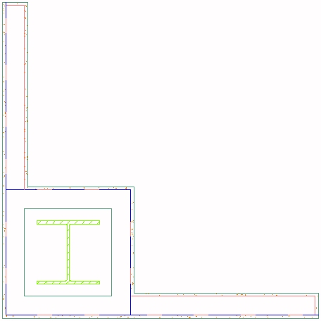
There are many ways to get a wall to "bumpout", whether for a column enclosure, a chase, or some other interruption. Each has its advantages and disadvantages, but my preferred way of dealing with this in metal stud and gypsum wallboard [GWB] construction is to have wall styles with GWB on only one side of the stud and "build" the bumpout just like it would be built in the real world.

This does add more walls to your drawing, including some short ones, but it offers great flexibility:
  • Draw the enclosure at any size.
  • Draw the enclosure in most any shape.
  • Position the enclosure anywhere along the length of a wall, including at the ends.
  • Edit the far ends of abutting walls without worrying whether the enclosure will be affected.
  • Edit the enclosure easily, on screen, without dialogs or in-place editing.
You can find the sample file that generated the image below in this thread in the Autodesk Architectural Desktop Discussion Group.

January 19, 2006

Half-inch GWB on Stud Wall Style

The out-of-the-box imperial walls styles use 5/8" GWB. That works fine for me, as that is my office's standard. If you want to use 1/2" GWB, you can easily make your own styles by using the following procedure. The example starts with a 3 1/2" stud, but you can apply the principles to any of the stud styles. Styles with multiple layers of GWB will require that the endcap polylines of several components be modified.

  1. Using the Style Manager or the Content Browser, bring the Stud-3.5 GWB-0.625 Each Side Wall Style into a new drawing. In the Style Manager [Walls category, under Architectural objects], edit the wall style.

  2. On the General tab, rename the style to Stud-3.5 GWB-0.5 Each Side. Edit the description to indicate 1/2" GWB.

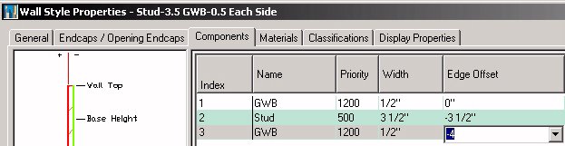
  3. On the Components tab, change the width of the GWB components [numbers 1 and 3] to 1/2". Change the edge offset of Component 3 to -4". OK out to your drawing.

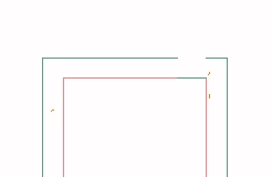
  4. Draw a "vertical" segment of the wall using the new style, from a point [say 0,0,0] to "@0,60". Zoom in on the upper end and note the gap in the endcap. This is because the endcap is was designed for 5/8" GWB, so ADT is scaling the endcap components down to make it fit 1/2" GWB, and that shortens up the part that is reaching across the stud.

  5. Still zoomed in, select the wall, right click and choose Endcaps > Edit In Place from the context menu. Select a point near the top end. If the left GWB component endcap polyline is highlighted, proceed, otherwise, hit Esc to deselect the right GWB component endcap polyline and select the left one. Grip edit the right end and stretch it to the right until it touches the left side of the right polyline. Click on the Save All Changes button of the In-Place Edit toolbar to save you changes.

  6. Open the Style Manager. In the Wall Endcap Styles category, rename the Stud-3.5 GWB-0.625 Each Side (End 1) style to Stud-3.5 GWB-0.5 Each Side (End 1), as you have changed the style to work with 1/2" GWB. Finally, in the Wall Opening Endcap Styles category, rename the Stud-3.5 GWB-0.625 Each Side (End 1)(2-Sided) style to Stud-3.5 GWB-0.5 Each Side (End 1)(2-Sided).

Now you can copy the modified wall style back to a source file [whether the out-of-the-box source file or one of your own, to make tracking your custom styles easier] and create a Tool palette tool from the new style. If you need to do this for many wall styles, you can save some time and rename the Wall Endcap Style at the same time you edit the Wall Style.

August 07, 2005

Modifying an Out-of-the-box Wall Style and Endcap

In response to a thread in the Autodesk Architectural Desktop 2006 Discussion Group, I posted a sample file and explanation of one way to take one of the out-of-the-box wall styles that has an endcap, and modify both the wall style and create a new endcap for the modified style. The example shows converting a wall style with 5/8" GWB on a metal stud to 1/2" GWB on the same metal stud.

The original poster managed to resolve his problem using in-place editing; my post explains how to use the WallEndcap command to generate the defining polylines of an existing Wall Endcap Style, then use those to create a new Wall Endcap Style for the modified wall style.