- Start a new Generic Annotation Family. From the Application Menu - Big "R" in the upper left corner - choose New > Family. In the New Family - Select Template File dialog, navigate to the folder where you or your firm have placed the Annotation Family Templates, and choose Generic Annotation.rft.
- Determine how your Key Plan needs to function. I do not want to have to place the Key Plan family separately on each Sheet; I want it to be part of the title block family so that it need only be placed once, and will always be in the exact same position on each Sheet. I also do not want to set up a title block family type for each Key Plan option. I do not want to show a Key Plan on every sheet in the set, so I will need a Key Plan type that shows nothing at all. There will be plans that show the overall building, as well as larger scale plans showing only one of the two wings. I want a solid fill to show in the Key Plan indicating the area that is being shown on that drawing. I also want to be able to show the Key Plan outline graphics with no fill.
- Create the graphics for your Key Plan. You are going to have to figure this one out on your own. There does not appear to be a way to make use of any sort of graphics in a project file and transfer them to a family file. You can scale graphics inside the family, so you could draw the building outline in the family to scale and then scale it down to fit the area available in your title block for your Key Plan. As shown below, I created scaled-down outlines of the two wings of my building and then added text to identify the wings, filled regions with solid black fill for each wing, and the north arrow graphics. Keep in mind that the intersection of the two reference planes will be the initial insertion point for your Key Plan family and position your graphics accordingly.

- In order to be able to control the display of the various graphic components, I created three type-based Yes/No parameters in the Family Types dialog. The first is for the outline, text and north arrow graphics that will be on whenever a Key Plan is to be displayed, but off when no Key Plan is to be shown. I called this parameter Outline.
- On the Modify ribbon tab, on the Properties panel, select the Family Types tool.

- In the Family Types dialog, click on the Add button in the Parameters area at the lower right side.

- In the Parameter Properties dialog, in the Parameter Data area, enter the name for the parameter, change the Type of Parameter to Yes/No, select a parameter category under which to group the parameter - I used Graphics and select the Type toggle. Click OK to add the parameter and dismiss the Parameter Properties dialog.

- In the Family Types dialog, I cleared the check mark in the value column, so that the current condition will be to not display the graphics.
Repeat the previous sub-steps to add the remaining two parameters, SectorA and SectorB, for the filled regions associated with each building section. Other than the Name, the parameter attributes are the same as those for the Outline parameter. Uncheck the toggle in the value column for these as well.


- On the Modify ribbon tab, on the Properties panel, select the Family Types tool.
- With the Family Types dialog still open, create a family type for each display condition you want for your Key Plan, and turn on the appropriate visibility parameters for each type. In the example, I created five: No Key Plan (all parameters unchecked), Outline Only (only Outline parameter checked), Sector A (only Outline and SectorA checked), Sector B (only Outline and SectorB checked) and Sectors A-B (all three checked).
- In the Family Types dialog, select the New button in the Family Types area at the upper right.

- In the Name dialog, enter the name for the Family Type in the Name edit box and click OK to register the entry and dismiss the dialog.

- In the Family Types dialog, set the appropriate value (checked or unchecked) for the visibility parameters for this type. (For the No Key Plan type, leaving all unchecked is correct.)

- Repeat the preceding sub-steps to add the remaining Family Types needed for your Key Plan, setting the appropriate values for each type.

- In the Family Types dialog, select the New button in the Family Types area at the upper right.
- Select all of the graphic elements in your Key Plan that are to be associated with one of the parameters (in my example, I started with the Outline parameter, to which everything but the filled regions will be assigned). On the Properties palette, look for the Visible parameter, under the Graphics parameter group. If you do not see it, you likely selected an object, such as a Reference Plane or a Group, which does not have this parameter. Deselect these items. Select the button at the right side of the Visible parameter line. (In versions prior to 2011, do this from the Instance Properties dialog for the selected items.)

- In the Associate Family Parameter dialog, choose the appropriate Yes/No parameter (Outline, for the graphics selected on the first pass) and then click OK.

- Notice on the Properties palette, the Visible parameter and its value are now grayed out and the button at the right side displays an equals sign ("="). This indicates that the Visible parameter has been linked to another parameter, and cannot be edited directly. You can click on the button to verify (or edit) the chosen parameter.

- Repeat the previous three steps to assign the SectorA and SectorB Yes/No parameters to the visibility of the associated graphics (in my example, the filled regions). Note: If you have any Detail Groups within your Key Plan Graphics, as I did to collect the various parts of the north arrow graphics, you will need to edit the group to be able to assign the appropriate visibility parameters to the nested graphics within the Detail Group.
- At this point, your Key Plan family is complete. Save the family.
- Open the Title Block family into which you will place the Key Plan. Load your Key Plan family into the title block family. (One way, with the Key Plan family open and current, on any of the standard ribbon tabs, on the Family Editor panel, choose the Load into Project tool. If you have multiple potential target files, choose only your Title Block family in the dialog presented.)
- Your Title Block family should be set current and you should be prompted to insert an instance of the Key Plan family. If you are not seeing any "ghost" graphics of your Key Plan family near your cursor, check the Properties palette to see what the default family type is. Mine was set to No Key Plan, which has no visible graphics, so I got no ghost graphics to aid in initial placement. I changed it to Sectors A-B so that I could see all of the graphics.

- Adjust the location of your Key Plan family in your title block, if necessary.

- Select the placed instance of the Key Plan.
- On the Options Bar, click on the down arrow at the right of the Label drop-down and choose <Add parameter...> from the list.

- In the Parameter Properties dialog, in the Parameter Data area, give the new parameter a name; I used Key Plan. Choose a Group for the parameter; I used Graphics once again. Make this parameter an Instance type. This is crucial, as doing so will allow each instance of your title block to have a different family type displayed, which is what you want.

- On the Home ribbon tab, on the Properties panel, click the Family Types tool.
- You should see the Key Plan (or whatever your called yours) Label listed as a parameter under the Graphics group (or whatever group you chose). Set the value for the Label to your desired default Key Plan family type. This is the value that newly created (or newly updated) title block instances will use. I chose to set mine to No Key Plan. (If your Title Block family has several family types, you will want to do this for each Family Type. This only sets the default value; each instance can be changed to show a different Key Plan type because we made the Label an instance parameter. This avoids the need to create a separate Title Block family type for each Key Plan type.)

- Save your Title Block family file.
- Load or reload your Title Block family into a project. On a Sheet that has an instance of this Title Block family, select the instance.
- On the Properties palette, notice that, under the Graphics parameter group (or whatever parameter group you assigned to the Label applied to the Key Plan instance in your Title Block family), there is now a parameter called Key Plan, the value of which is a drop-down list of the family types you created in your Key Plan family. Choose the type you want to see for that particular Sheet.

October 19, 2011
Revit Key Plans - More Detail
It has come to my attention that my Revit Key Plans article can be hard to follow, particularly if you are not familiar with some of the concepts or procedures used. It was not intended to be a step-by-step tutorial, so I am providing this post to fill in some of the gaps and make it easier to follow along. This tutorial was prepared using Revit Architecture 2011; interface elements in other versions or releases may vary.


October 11, 2011
ACA Openings with "Style"
The Opening object in ACA does not have styles. So, unlike Doors, Windows and many other ACA object types, you can not control the display of Openings with overrides at the style level, nor can you attach style-based Property Sets. Given the relatively limited display components associated with Openings,
 not having styles may not be a problem for you. But if you have ever wanted to show different types of Openings in different ways, and wished that you could control these displays at the style level, rather than having to make the changes on each individual Opening, then you may be interested to know that it is possible use a Door to emulate an Opening, and thereby gain the benefits of having an Opening-like object that has styles. Another advantage of doing this is that you can assign a Profile to a Door Style acting as an "opening", allowing you to have non-rectangular "openings".
Before diving into the specifics, it is worth noting some of the limitations. If you make use of the Fill Types in the plan display of Openings, and you use a hatch pattern other than Solid Fill for the fill, you will likely be disappointed, as the use of a unit block to mimic the Fill Types will almost always result in a distortion of the hatch pattern since the Width and Depth dimensions will likely result in unequal scaling of the block. Another minor limitation is that, unlike when selecting the Triangle A or Triangle B Fill Types, the display of Cross Line B will not automatically be suppressed when turning on the display of the custom block for Triangle A or Triangle B. The four Fill Types are also not mutually exclusive - you could accidentally have more than one turned on at a time. If none of the above are deal breakers for you, then read on to see what is needed to set up a Door Style to enable "openings" with style.
Custom Blocks
In order to duplicate the components available in an Opening object, you will need to create eight "unit" blocks, one for each component. A description of unit blocks can be found in this blog post. The graphics of each unit block fit within a one-unit by one-unit area; the eight unit blocks can be seen in the image below. The insertion point is in the lower left corner of each block. The linework or hatch in each block is drawn on Layer 0, with Color, Linetype, Plot style (if you use named plot styles) and Lineweight set to ByBlock, so that the Display System will be able to contol all of these properties.
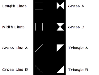 The four blocks on the left side provide the graphics for the equivalent of the Length Lines, Width Lines, Cross Line A and Cross Line B components of an Opening. The four blocks on the right side provide the equivalent of the four Fill (Hatch) Types: Cross A, Cross B, Triangle A and Triangle B, provided that you set the Hatch component to use a Solid hatch.

Door Style as Opening
With the custom blocks defined, you can now create the Door Style that will be used as a style-based "opening". The following steps will show how to do that, matching the out-of-the-box Display settings for Openings; if your office has customized those settings, you will likely want to use those instead. On the Manage ribbon tab, on the Style & Display panel, click the Style Manager tool to open the Style Manager. Expand the Architectural Objects node (under the drawing in which the unit blocks are defined) and select the Door Styles node. In the right pane, right click on the Standard Door Style and choose Copy from the context menu, and then right click over a blank area on the right pane and choose Paste to create a copy. In the left pane, select the new copy (mine was called Standard (2)) and choose the General tab. Rename the style in accordance with your firm's naming convention. (I used Door as Opening for my example style, and provided a description for the style.)
 On the Dimensions tab, in the Frame area in the upper right, set the width to 0" and make certain that the Auto-Adjust to Width of Wall toggle is checked. Simply turning off the Frame component is not enough - you need to set the Width of the Frame component to 0 here so that the Width set on the Door (as Opening) will also be the width of the actual opening created in the Wall.
 On the Design Rules tab, change the Door Type to Pass Through. If you are looking to create a non-rectangular opening, you would assign the profile on this tab.
 You can set up standard sizes on the Standard Sizes tab, if you like. On the Display Properties tab, click on the toggle in the Style Override column for the Plan Display Representation to set and edit a style-level override.
 The Display Properties dialog will open. On the Layer/Color/Linetype tab, turn off the display of all components by clicking on all yellow lightbulbs in the Visible column to turn them off.
 This will suppress the display of the standard Door components in a plan view. The custom blocks will now be added to provide the equivalent of the components for Openings. On the Other tab of the Display Properties dialog, click on the Add button.
 In the Custom Block dialog, do the following:
 Repeat the process above to add the blocks for the Width Lines, Cross Line A, Cross Line B, Cross A, Cross B, Triangle A and Triangle B custom display blocks. I used the same settings for each block.
 Return to the Layer/Color/Linetype tab. In addition to the out-of-the-box components previously shown here, you will find that each of your custom blocks is now listed as a display component.
 This is where you will control the visibility and display parameters of the custom blocks. You will not have a Fill type tab, as an Opening object does; instead, you will need to control the display of each fill option individually, here. You also will not have a Hatching tab, so, as noted at the beginning of this post, you will not be able to select a hatching type - solid fill is "hard coded" into the custom display block of each fill type. In order to match the out-of-the-box display for Openings, you will need to turn off all of the custom display blocks except for the Length Lines block, and set the display parameters as shown in the image below.
 You are, of course, free to use your own settings. Click OK in the Display Properties dialog to register the changes made to the Door as Opening Door Style. In the Style Manager, click OK to save the changes to the drawing file (and then save the drawing file), or click Apply if you want to continue editing styles in the Style Manager. To test your new style, you can either make duplicates the style and then modify the style-level override display settings in each to turn on different sets of components, to verify that each works as expected, or you can place multiple instances of your Door as Opening "with style" and then apply object-level overrides to test each component's display. Ultimately, you will want to create multiple styles, since the whole point of creating this Door Style was to be able to control the display of "openings" at the style level. To complete the emulation of an Opening object, you will need to create a Tool palette tool for each Door as Opening Door Style and that uses the OPENING Layer Key as an override, so that the Door object created get placed on the same layer as an Opening object (by default).
If you use the Schedule Feature to create a Door Schedule for your "real" Doors and do not want these "opening Doors" showing up in the Schedule Table, you can apply a Layer Filter to your Door Schedule or you can set up and apply a Classification Definition to exclude the opening Door Styles from your Schedule Table. Refer to this blog article for more information on filtering the objects in a Schedule Table.
You can find a sample file that contains the style used to generate the screen captures shown here, along with some copied styles with different custom blocks turned on, in this thread in the AutoCAD Architecture Content Discussion Group.

Before diving into the specifics, it is worth noting some of the limitations. If you make use of the Fill Types in the plan display of Openings, and you use a hatch pattern other than Solid Fill for the fill, you will likely be disappointed, as the use of a unit block to mimic the Fill Types will almost always result in a distortion of the hatch pattern since the Width and Depth dimensions will likely result in unequal scaling of the block. Another minor limitation is that, unlike when selecting the Triangle A or Triangle B Fill Types, the display of Cross Line B will not automatically be suppressed when turning on the display of the custom block for Triangle A or Triangle B. The four Fill Types are also not mutually exclusive - you could accidentally have more than one turned on at a time. If none of the above are deal breakers for you, then read on to see what is needed to set up a Door Style to enable "openings" with style.
Custom Blocks
In order to duplicate the components available in an Opening object, you will need to create eight "unit" blocks, one for each component. A description of unit blocks can be found in this blog post. The graphics of each unit block fit within a one-unit by one-unit area; the eight unit blocks can be seen in the image below. The insertion point is in the lower left corner of each block. The linework or hatch in each block is drawn on Layer 0, with Color, Linetype, Plot style (if you use named plot styles) and Lineweight set to ByBlock, so that the Display System will be able to contol all of these properties.


Door Style as Opening
With the custom blocks defined, you can now create the Door Style that will be used as a style-based "opening". The following steps will show how to do that, matching the out-of-the-box Display settings for Openings; if your office has customized those settings, you will likely want to use those instead. On the Manage ribbon tab, on the Style & Display panel, click the Style Manager tool to open the Style Manager. Expand the Architectural Objects node (under the drawing in which the unit blocks are defined) and select the Door Styles node. In the right pane, right click on the Standard Door Style and choose Copy from the context menu, and then right click over a blank area on the right pane and choose Paste to create a copy. In the left pane, select the new copy (mine was called Standard (2)) and choose the General tab. Rename the style in accordance with your firm's naming convention. (I used Door as Opening for my example style, and provided a description for the style.)


- Click the Select Block button and choose a block definition to add as a custom display block in the Select a Block dialog. In the example, the Dr as Opng - Length Lines block is selected. This is the Length Lines block illustrated above. Click OK to register your change - the block name will be displayed to the right of the Select Block button.
- Choose the conditions under which the custom block will display (Always, When Intersectiong Cut Plane, When Above Cut Plane, When Below Cut Plane). In a brief experiment, I found that Opening object components, when "on", appear to display regardless of whether the Opening is cut by the cut plane, above the cut plane or below the cut plane, so I left all of my custom blocks set to Always display. You may choose to do differently, if it meets your needs.
- In the Scale to Fit area, enable the scaling toggles for Width and Depth. This will cause our unit block to be scaled to match the user specified Width for the Door object and the width of the partition (because we enabled the Auto-Adjust to Width of Wall toggle on the Dimensions tab of the style). Since the block only contains 2D (plan) graphics, we do not need to scale it for Height. Choosing both Width and Depth scaling will disable the Lock XY Ratio toggle, which we would not want to use here.
- Clear all of the Mirror In toggles (none should be selected when first adding a block; verify that none are selected).
- Set the Insertion Point to X: Left, Y: Front and Z: Bottom, if it is not already set that way. This coordinates with the insertion point of the unit block being in the lower left corner of the block's extents.
- No Insertion Offset is required; verify all values are set to 0.
- The only choice of Component for a Door is Frame Component. Verify it is set to Outside, which should be the default value.


If you use the Schedule Feature to create a Door Schedule for your "real" Doors and do not want these "opening Doors" showing up in the Schedule Table, you can apply a Layer Filter to your Door Schedule or you can set up and apply a Classification Definition to exclude the opening Door Styles from your Schedule Table. Refer to this blog article for more information on filtering the objects in a Schedule Table.
You can find a sample file that contains the style used to generate the screen captures shown here, along with some copied styles with different custom blocks turned on, in this thread in the AutoCAD Architecture Content Discussion Group.
October 08, 2011
ACA 2012 Service Pack 1 Released
Apparently Autodesk has decided to go back to calling them Service Packs, rather than Updates. Service Pack 1 for AutoCAD Architecture 2012 is now available - download it from here.
Be certain to read the README for installation instructions. According to the README, Service Pack 1 restores the former ARRAY command functionality, in a new command called ARRAYCLASSIC. There is also a new System Variable, SNAPGRIDLEGACY: set this to 1 to have the cursor always snap to the grid (legacy snap behavior); set it to 0 to have it snap to the grid only when AutoCAD has prompted for point input.
The following ACA defects have been addressed:
Drawing Manager
The following AutoCAD defects have been addressed:
3D Navigation Tools
Be certain to read the README for installation instructions. According to the README, Service Pack 1 restores the former ARRAY command functionality, in a new command called ARRAYCLASSIC. There is also a new System Variable, SNAPGRIDLEGACY: set this to 1 to have the cursor always snap to the grid (legacy snap behavior); set it to 0 to have it snap to the grid only when AutoCAD has prompted for point input.
The following ACA defects have been addressed:
Drawing Manager
- Selecting a sheet with a long name may cause unexpected behavior in AutoCAD Architecture.
- Opening a project with a large number of files in a 64-bit machine may cause AutoCAD Architecture to crash.
- Space containment does not work on a 64-bit operating system.
- Exporting multi-view blocks to AutoCAD may result in an incorrect size.
- Some AEC ARX files are loaded when running AutoCAD Architecture with an AutoCAD profile.
- Renovation function fails when you add a door or window object during renovation mode.
- Sometimes the renovation toggle remains enabled even after exiting the renovation mode.
- Building geometry may change after you activate and then disable the live section.
- Roof or roof cap solid hatch might be displayed in section incompletely.
- Some merged space area are calculated incorrectly.
- When the unit area is inconsistent with its unit length, the calculated space area might be inaccurate.
- Adjusting column grid can cause beams to lose connection with the columns.
- Adding tags for doors on multiple reference copies may cause unexpected behavior in AutoCAD Architecture.
- REPOSITIONALONG command does not work for doors and windows.
- Running the JOIN command on two connected walls may cause unexpected behavior in AutoCAD Architecture.
- When you offset a wall using another wall with the same direction as the reference, the offset wall may be created in the opposite direction.
- The Below Cut Plan display component of doors or window may not display.
The following AutoCAD defects have been addressed:
3D Navigation Tools
- 3DConnexion settings are not being remembered after changes are made.
- 3Dconnexion device will not cancel the current command.
- With dynamic input off dragging the height handle of an extruded line will not always stretch by the value and direction of the drag.
- AutoCAD may become unstable when rebuilding a helix to a spline where the selection was not dropped.
- AutoCAD may become unstable while attempting to load a DCL file with errors from a long file name.
- Tooltip does not appear when Additional tool tip string is set in “AcEdInputPointMonitor::monitorInput”.
- API fix: This fix will respect the custom color, line pattern and line weight when selecting the entities including external reference.
- Autoloader fails when SeriesMax parameter set to linked.
- Autoloader loads partial CUI but may not display it when the bundle is removed and reinstalled.
- When platform="AutoCAD*", bundles will be load on ACAD and Vertical.
- Using Autoloader to add custom CUI files that contain WPF Custom Controls will not work as it needs a registry entry.
- AutoCAD may become unstable while snapping to blocks containing OLE objects.
- Editing attribute text in EATTEDIT dialog sometimes results in a fatal error.
- When a drawing is saved from within the Block Editor, the entire content of the drawing is sometimes lost and replaced with the content of the block being edited.
- Sometimes there is a delay while trying to modify blocks containing a Block Table Parameter.
- AutoCAD becomes unstable when entering the block editor, attempting to edit a dynamic block which has geometry on a locked layer.
- Sometimes the BEDIT toolbar does not get hidden after exiting block editor.
- You may receive an error at the command line after enabling a WinTab driver and the tablet will not function.
- Integrated chipsets are unable to return available video memory correctly.
- Arcs and circles viewed on edge appear as a single line. This changes 2D DWF/DWFx drivers to plot them as a single line, rather than a polyline.
- AutoCAD may become unstable when using the "UNDO" command on drawings that are 2 gigabyte or larger.
- Ordinate dimensions in paper space are not correctly reflecting the distance from paper space UCS.
- AutoCAD may become unstable while closing a drawing after etransmitting it using the COM API.
- Autodesk Exchange may display a non-subscription link after updating to a subscription serial number.
- User login IDs that contained special characters like “@” could not log in to online services.
- AutoCAD may become unstable when using the NCOPY command.
- Overkill may delete polylines incorrectly when working with reversed polylines.
- Overkill may not work well when there is an arc segment in between 2 line segments.
- AutoCAD may become unstable when using the “separate hatch” option.
- Multi frame QuickBird Tiff image files may not display expected colors.
- When trying to insert an Adobe Photoshop PSD file it was not visible in the file filter list.
- AutoCAD may become unstable when inserting an AdobePhotoshop PSD file.
- Changing layer colors of layers beginning with non-alphanumeric characters may result in other layers changing colors.
- The layer state Ribbon control does not honor the apply properties viewport overrides.
- AutoCAD may become unstable when drawings with multileaders are saved to older versions.
- AutoCAD may become unstable when editing polylines.
- NCOPY may fail to copy objects contained in blocks that were inserted into paper space.
- Mtext Paragraph spacing value cannot be edited once a value is set.
- True Type (TTF) font text or mtext is blurry, bold, and distorted when the viewport is non-orthogonal because XY values are not exactly zero.
- AutoCAD may become unstable when copying from an Excel file back to AutoCAD.
- Cannot open drawing files from file Explorer if the drawing contains a "'%'" in the file name.
- AutoCAD may stop responding when saving and or opening drawings with Symantec Norton 360 Version 5 installed on your system.
- You will be unable to open drawings created using a non-Autodesk product when using the Open() API.
- AutoCAD may become unstable when selecting the grid in some drawings.
- AutoCAD may become unstable after editing MTEXT in a viewport and when exiting the program.
- Area is wrong when coincident constraints are applied to entities.
- AutoCAD may become unstable when using PDF Export on files that contain MS Mincho font.
- AutoCAD may become unstable when unloading a PDF underlay.
- AutoCAD may become unstable when an undefined PDF underlay is unloaded.
- AutoCAD may become unstable when plotting drawings that include “MS Mincho” to PDF.
- Drawings containing many layers may become slower with each pan and zoom operation when the ribbon is active. Performance improvement in 64bit COM APIs.
- You may experience data loss when sending multiple plots to Xerox printers.
- AutoCAD may become unstable when selecting plot preview.
- AutoCAD may become unstable when using the purge command.
- The linetype preview may be missing from the linetype dropdown in Ribbon Properties panel when opening drawings from the Application Menu.
- Ribbon Combo Box text eight may be empty when using "TEXTEDIT" on multiple dimensions.
- With Snap enabled, the cursor does not move to snap intervals.
- Turning SNAPGRIDLEGACY ON will restore the old Snap behavior of the cursor when no command is active.
- Restores legacy SNAP behavior during certain LISP-based selection commands.
- Sheet List Table Context menu in Sheet Set Manager (SSM) is missing some menu items.
- Cell style is grayed out when picking inside any cell.
- The data link menu is grayed out after inserting a data link in a table.
- AutoCAD may become unstable attempting to edit a polyline vertices Pedit tangent.
- AutoCAD may become unstable in group selection where the group contains a box.
- When objects are on locked layers you are able to nudge them.
- AutoCAD may become unstable when interacting with the ViewCube while grip editing.
- When right click menus are disabled, selection or crossing right click actions are incorrect.
- AcFocusCtrl cannot be inserted in a VBA form.
- Attribute dialog will be displayed when inserting a block with attributes based on the setvar ATTDIA value.
- AutoCAD may become unstable when using osnap in a 2d hide view.
- AutoCAD may become unstable when interacting between the open dialog and the XREF manager.
- AutoCAD may become unstable when zooming over the XY indicator in Layout.
September 02, 2011
Unit Blocks
A unit block is an AutoCAD block definition in which all of the graphics are drawn within the confines of a one-unit by one-unit area (or, for 3D blocks, a one-unit by one-unit by one-unit volume). The block can then be inserted with X- and Y-scale factors (or X-, Y- and Z- scale factors in the case of a 3D block) equal to the actual size of that instance.
For example, HVAC supply diffusers are often represented by a rectangle with opposite corners connected by diagonal lines

You could set up a number of blocks for all of the different sizes you would need (or, in more recent versions, master the creation of dynamic blocks). Or, you can create a single, unit block and then set the X- and Y- scale values to get the size needed for a particular instance.

The unit block concept remains useful, even with the advent of dynamic blocks, as ACA objects that use blocks (such as for the view blocks of Multi-View Blocks or for custom display blocks added to many object types) often can take advantage of the unit block concept, and dynamic blocks will not remain dynamic when nested within an ACA object.

You could set up a number of blocks for all of the different sizes you would need (or, in more recent versions, master the creation of dynamic blocks). Or, you can create a single, unit block and then set the X- and Y- scale values to get the size needed for a particular instance.

The unit block concept remains useful, even with the advent of dynamic blocks, as ACA objects that use blocks (such as for the view blocks of Multi-View Blocks or for custom display blocks added to many object types) often can take advantage of the unit block concept, and dynamic blocks will not remain dynamic when nested within an ACA object.
August 30, 2011
Early AU Registration for AU Members
 "Early" registration for AU 2011 is now open for AU members. Regular registration starts September 7. Register at the AU website.
August 17, 2011
Autodesk University 2011 Course Catalog
The class catalog is out for Autodesk University 2011.
Anyone still wondering where Autodesk's priorities lie may want to consider that setting Autodesk Revit Architecture as the Software and leaving all other filters set to All (or, for Keywords, blank) returns 137 hits.
Doing the same for AutoCAD Architecture returns 22 hits. Of those 22 hits, a number are actually Revit Architecture classes incorrectly classified or are about making the transition from ACA to RA. Two are AMEP classes. Quite a few others are about some other topic but mysteriously list AutoCAD Architecture as the software.
So ACA actually only has one hands-on lab and four lectures (one of which mentions ACA in the title but lists Navisworks as the primary software). Yet somehow they managed to set up the schedule such that there are two time conflicts, so at most you could take three ACA-related classes. Hardly worth the cab fare from the airport.
No doubt there are misclassifications in the 137 hits for Revit Architecture, and there are unconference and virtual classes in there too, but I bet you can fill just about every class slot with something related to Revit Architecture.
Anyone still wondering where Autodesk's priorities lie may want to consider that setting Autodesk Revit Architecture as the Software and leaving all other filters set to All (or, for Keywords, blank) returns 137 hits.
Doing the same for AutoCAD Architecture returns 22 hits. Of those 22 hits, a number are actually Revit Architecture classes incorrectly classified or are about making the transition from ACA to RA. Two are AMEP classes. Quite a few others are about some other topic but mysteriously list AutoCAD Architecture as the software.
So ACA actually only has one hands-on lab and four lectures (one of which mentions ACA in the title but lists Navisworks as the primary software). Yet somehow they managed to set up the schedule such that there are two time conflicts, so at most you could take three ACA-related classes. Hardly worth the cab fare from the airport.
No doubt there are misclassifications in the 137 hits for Revit Architecture, and there are unconference and virtual classes in there too, but I bet you can fill just about every class slot with something related to Revit Architecture.
July 23, 2011
ACA: Adding a Style-Based Property Set
A style-based Property Sets is handy in that you only need to attach it to the Style or Definition once, and then it travels with the Style without any additional effort on your part. Most automatic properties are good candidates for a style-based Property Set, as are manual properties whose values remain constant for all instances of the Style or Definition. Location properties should generally be in object-based Property Sets, since the location grip will not be generated unless the object has at least one Location property in an object-based Property Set.
Creating a style-based Property Set is quite easy. When creating the Property Set Definition in the Style Manager, indicate that it should apply to Styles and Definitions by using the radio button at the top of the Applies To tab.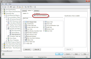
Then pick the object type(s) to whose style(s)/definition(s) the Property Set Defintion is to apply. Go to the Definition tab and add the properties you want in the set, if you have not already done so.
Now that you have a style-based Property Set Definition, you need to attach it to one or more styles/definitions (of the type you chose on the Applies To tab). In the Style Manager, create/edit such a style or definition. On the General Tab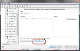 click on the Property Sets... button. This will open the Edit Property Set Data dialog. If your style or definition does not already have a style-based Property Set attached, the dialog will be blank. Click on the Add Property Sets button (right button at the lower left corner). Note that the button will not be active if there are no style-based Property Sets in the current drawing that apply to the object style/definition being edited and that have not already been added. In the Add Property Sets dialog, review the list of eligible Property Sets and make certain that a check mark is in front of all those you wish to add (and not in front of any you do not want to add), and then click OK to add the Property Sets.
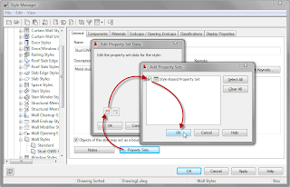 This will return you to the Edit Property Set Data dialog, and you can review the attached properties and, if there are manual properties, you can set the desired values. Also note that now that this style has a Property Set added, the Remove Property Sets button is now active (right button at lower left, next to Add Property Sets button). Click OK to accept the changes you made, and now your style-based Property Set is attached and the Properties therein are available to Schedule Tables and Schedule Tags.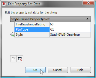
For office-standard style-based Property Sets, you will want to add the set to your style/definition source file, so when users add the style/definition to a drawing, the Property Set is already attached.
Creating a style-based Property Set is quite easy. When creating the Property Set Definition in the Style Manager, indicate that it should apply to Styles and Definitions by using the radio button at the top of the Applies To tab.

Then pick the object type(s) to whose style(s)/definition(s) the Property Set Defintion is to apply. Go to the Definition tab and add the properties you want in the set, if you have not already done so.
Now that you have a style-based Property Set Definition, you need to attach it to one or more styles/definitions (of the type you chose on the Applies To tab). In the Style Manager, create/edit such a style or definition. On the General Tab
 click on the Property Sets... button. This will open the Edit Property Set Data dialog. If your style or definition does not already have a style-based Property Set attached, the dialog will be blank. Click on the Add Property Sets button (right button at the lower left corner). Note that the button will not be active if there are no style-based Property Sets in the current drawing that apply to the object style/definition being edited and that have not already been added. In the Add Property Sets dialog, review the list of eligible Property Sets and make certain that a check mark is in front of all those you wish to add (and not in front of any you do not want to add), and then click OK to add the Property Sets.
 This will return you to the Edit Property Set Data dialog, and you can review the attached properties and, if there are manual properties, you can set the desired values. Also note that now that this style has a Property Set added, the Remove Property Sets button is now active (right button at lower left, next to Add Property Sets button). Click OK to accept the changes you made, and now your style-based Property Set is attached and the Properties therein are available to Schedule Tables and Schedule Tags.
For office-standard style-based Property Sets, you will want to add the set to your style/definition source file, so when users add the style/definition to a drawing, the Property Set is already attached.
June 06, 2011
Revit Tip - Unwanted Linework Revisited
Thanks to a comment posted by Andrew to my Revit Tip - Masking Regions post, I am a step further along on my Revit journey. He correctly pointed out that the Linework tool would be a better choice for getting rid of the unwanted line.
On the Modify ribbon tab, on the View panel, click on the Linework tool, shown below in Revit Architecture 2011.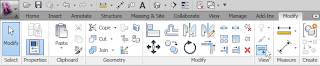 (As always, click on any reduced-size image to see the image full size. Use the Back button on your browser to return here.)
On the Modify|Linework ribbon tab, on the Line Style Panel, set the Line Style to <Invisible lines> in the Line Style drop down list.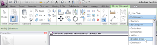 Now you can select the unwanted linework in the View in which you do not want to see it, and make it invisible with a single click. That is far more efficient than using a Masking Region to hide a single line.
If you change your mind later, you can restore the linework you made invisible by using the same Linework tool and setting the Line Style to <By Category> (or any other visible Line Style, if you do not want to use its default appearance).
On the Modify ribbon tab, on the View panel, click on the Linework tool, shown below in Revit Architecture 2011.
 (As always, click on any reduced-size image to see the image full size. Use the Back button on your browser to return here.)
On the Modify|Linework ribbon tab, on the Line Style Panel, set the Line Style to <Invisible lines> in the Line Style drop down list.
 Now you can select the unwanted linework in the View in which you do not want to see it, and make it invisible with a single click. That is far more efficient than using a Masking Region to hide a single line.
If you change your mind later, you can restore the linework you made invisible by using the same Linework tool and setting the Line Style to <By Category> (or any other visible Line Style, if you do not want to use its default appearance).
June 01, 2011
Update 2 for ACA 2011 Now Available
You can download Update 2 for AutoCAD® Architecture 2011 here.
According to the Readme, this Update is NOT cumulative; you will need to install Update 1 first, if you have not already done so. Be certain to read through the entire Readme before installing the update. According to the Readme, the following ACA items have been addressed in Update 2:
Annotation Scaling
Detail Components
Doors/Windows
Drawing Management
General UI
Multi-View Blocks
OpenLight
Structural Members
Walls
See my previous article, for the Updates addressed by Update 1.
According to the Readme, this Update is NOT cumulative; you will need to install Update 1 first, if you have not already done so. Be certain to read through the entire Readme before installing the update. According to the Readme, the following ACA items have been addressed in Update 2:
Annotation Scaling
- If two drawing units are different, the annotative blocks of the previous drawing version might be inserted with incorrect scale.
Detail Components
- Some detail components might not be added in the UK profile after installing Update 1.
Doors/Windows
- When you insert doors or windows evenly between the grid line or between walls, the elevation of the inserted doors or windows may result to a zero value.
Drawing Management
- Clearing the XML file in the current project may cause AutoCAD Architecture to crash.
- Renaming or renumbering the sheet in the Project Navigator may cause AutoCAD Architecture to crash.
General UI
- Accessing some tools from the Tool palettes may cause AutoCAD Architecture to crash.
Multi-View Blocks
- Exporting Multi-View Blocks to AutoCAD may result in incorrect sizes.
- In 3D shaded visual styles, a Multi-View Block created from circle with specified thickness might be drawn double.
OpenLight
- When the OpenLight plug-in is installed, the changes in the display configurations may not be maintained.
Structural Members
- When the start offset of a structural member is larger than its logical length, may cause AutoCAD Architecture to crash.
Walls
- Changing the view cube from parallel to perspective from the shortcut menu after selecting a wall may cause AutoCAD Architecture to crash.
- Clicking the Add Vertex button for some walls while editing in-place may cause AutoCAD Architecture to crash.
- Converting a 3D solid object created by extruding profile along a certain path to wall may cause irregular geometry.
- If the walls are with separate wall components which have bottom elevation offset, these walls may not display correctly in plan view.
See my previous article, for the Updates addressed by Update 1.
May 06, 2011
Revit Tip - Masking Regions
This may be old news to more experienced Revit users, but this was not covered in the "basics" training and was not discovered by anyone on my project team during the design and documentation phases. When generating elevations and sections from the Revit model, there will often be "artifacts" in the view that you would not want to see in the final elevation or section. Or there will be items that do not appear as you would like, but the effort to edit the model to get them to show properly in elevation or section is simply not worth it or the overhead of modeling the necessary detail slows the model excessively.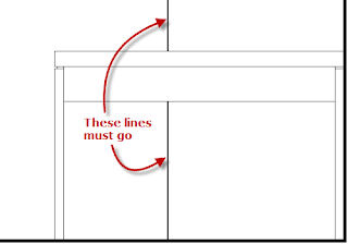
Masking Regions to the rescue! The problem we had with the Masking Regions was that the items to be masked almost always intersected or abutted linework that we wanted to keep. The boundary lines for Masking Regions default to invisible lines, which makes sense, but, unfortunately, if you place the boundary at the linework you want to keep, the mask extends to the midpoint of that linework. This is particularly noticeable on linework with a heavy lineweight, but is true for all linework.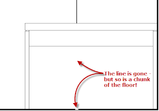
The initial solution was to grip edit the Masking Region and pull it back slightly, to avoid losing desired graphics. This was tedious, and, when done poorly, either left a (smaller) divot in the linework to remain, or left a small part of the line to be masked protruding. While my efforts during construction documents were mostly focused in other areas, I have had to make revisions during construction, and found this process to be very unsatisfactory, until I realized that the boundary lines do not have to be invisible, nor do they all have to be the same.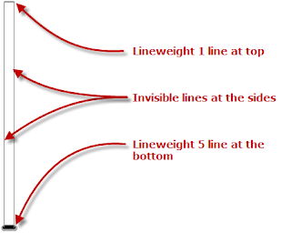 By matching the Line Style of the boundary lines to that of the linework for segments that align with linework to remain, the Masking Region fully hides the unwanted linework without removing a piece of the linework that is to remain.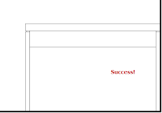

Masking Regions to the rescue! The problem we had with the Masking Regions was that the items to be masked almost always intersected or abutted linework that we wanted to keep. The boundary lines for Masking Regions default to invisible lines, which makes sense, but, unfortunately, if you place the boundary at the linework you want to keep, the mask extends to the midpoint of that linework. This is particularly noticeable on linework with a heavy lineweight, but is true for all linework.

The initial solution was to grip edit the Masking Region and pull it back slightly, to avoid losing desired graphics. This was tedious, and, when done poorly, either left a (smaller) divot in the linework to remain, or left a small part of the line to be masked protruding. While my efforts during construction documents were mostly focused in other areas, I have had to make revisions during construction, and found this process to be very unsatisfactory, until I realized that the boundary lines do not have to be invisible, nor do they all have to be the same.
 By matching the Line Style of the boundary lines to that of the linework for segments that align with linework to remain, the Masking Region fully hides the unwanted linework without removing a piece of the linework that is to remain.
Subscribe to:
Posts (Atom)