I still have no idea how Chris Yanchar’s "reply" got posted "before" Matt’s initial post (there would not have been anything to print before Matt posted), especially since that was before he became an Autodesk employee. The interface for editing Layer Standards has not changed significantly since ADT 2, so if you want to run through Matt’s tutorial, in Step 2 change "Desktop->Layer Management->Layer Manager" to "Format->Layer Management->Layer Manger…" to open the Layer Manager Dialog, and then click on the Layer Standard button on the far left of the toolbar in that dialog to open the Layer Standards dialog and you are good to go.
Before I totally forget what I learned from both Matt and my own ventures into Layer Standards, and to partially rectify the loss of the nicely formatted version of the Brain Dump that had been available, I thought it might be worthwhile to put together a blog post on the subject. Even if you intend to make use of the out-of-the-box Layer Standard most appropriate for the area of the world in which you work, understanding how that Layer Standard works will be helpful, particularly if, like the AIA Version 3 Layer Standard, not all of the officially sanctioned field values for all disciplines are included in the out-of-the-box Layer Standard.
Layer Standard Overview
First, a brief overview of what a Layer Standard does (and does not) do. A Layer Standard is a way of defining a layer naming convention in which the layer name is composed of consistent "Descriptive Fields," or sub-sections. In an AutoCAD Architecture Layer Standard, you first define Component Fields, which are the smallest units that make up a layer name. One or more of these Component Fields are then combined into Descriptive Fields, which are the building blocks the user will see. These Descriptive Fields will be the fields from which you make a "New Layer from Standard" in the Layer Properties Manager or in the Layer Name dialog when assigning a Layer Name to a Layer Key in a Layer Key Style as well as those to which you assign Layer Key Overrides. Once you have defined the Descriptive Fields, you can "Edit Descriptions," where you can enter allowable values for each of the Descriptive Fields and enter a description. These values become the values that you can select when building a layer name in the Layer Properties Manager or in a Layer Key Style, and the descriptions can be made part of the layer description that shows in the Description column of the Layer Properties Manager. Finally, you can specify which fields should be included in that layer description, and provide any linking text to appear before each field’s description. The Layer Standard does not define any layers, but does contain the rules for creating layer names that comply with the Layer Standard, as well as pre-defined field values to speed the creation of a new layer name. The Layer Standard also does not prevent you from creating a non-compliant name, but it will not allow such a layer name to be associated with that Layer Standard.
Analyzing Your Layer Naming Convention
The first step, before you venture into creating a Layer Standard of your own, would be to analyse your layer naming convention and determine if you can break your layer names into separate fields, and then determine what rules apply to each of the fields. If the way you name your layers can not be broken down into separate fields with predictable positioning and lengths, then a Layer Standard is not for you. I will do this with the out-of-the-box AIA Version 3 Layer Standard, since that is the standard with which I am most familiar, with apologies to those from other areas where a different Layer Standard and associated Layer Key Style is the norm.
The AIA Version 3 Layer Standard can be broken down as follows:
Discipline Designator: A one- or two-alphabetic-character field that designates the discipline associated with that layer. The first, required character designates the discipline, and the optional second character designates a sub-discipline within the main discipline.
Major: A four-alphabetic-character field designating the "major" building system to which the layer applies.
Minor 1: A four-character field designating a "minor" building sub-system or other layer modifier to which the layer applies.
Minor 2: A four-character field designating a second "minor" building sub-system or other layer modifier to which the layer applies.
Status: A single-character field designating the construction "status" of the layer (new work, existing to demolish, existing to remain, phase number, etc).
Importing/Creating New Layer Standards in 2009
If you intend to either examine the out-of-the-box Layer Standards or create a new one from scratch and you are working in AutoCAD Architecture 2009 (and, possibly AutoCAD ® MEP, although I have no access to that to find out if the same issue takes place there as well), take a look at this blog article regarding the need to do something in the Layer Properties Manager to trigger all other pending changes, such as importing or making changes to Layer Standards, in order to get them to be saved. You do not want to lose work you thought would be saved to this bug in 2009.
Speaking of out-of-the-box Layer Standards, in the default installation, the source files can be found in the C:\Documents and Settings\All Users\Application Data\Autodesk\ACD-A 2009\enu\Layers folder; your content location may be different, if your installation modified the location of content folders. AecLayerStd.dwg contains the AIA (256 Color) Layer Key Style and associated AIA Version 3 Layer Standard, as well as several United Kingdom and German Layer Key Styles and Layer Standards. Depending upon what country-specific content you may have chosen to install, you may also have additional AecLayerStd*.dwg files that include country-specific standards. I believe I installed all of the content available on the 2009 DVD I got, and have files for the Denmark, Finland, Norway, Sweden and the UK. There may be other country- or region-specific standards files that are made available in those countries and regions as well.
While you are learning about this feature, I would not recommend editing the out-of-the-box styles in any of the source files. Either import them into a new file (in 2009, remember to add/delete a new layer prior to selecting OK in the Layer Properties Manager to save the imported Layer Standards properly) or make a copy of the source file under a different name in a different folder. You can then poke at them to your heart’s content, knowing that any changes you make (for better or worse) will only affect those standards in that single file.
Creating and Editing a Layer Standard
Once you have broken down your layer naming convention and thought about some rules with which each field is to comply, you can create a new Layer Standard and set it up with the fields and rules to suit. For those whose aim is simply to understand Layer Standards better, and perhaps to edit an existing one, open a file that has a Layer Standard in which you are interested, and jump in at Step 5 ("edit") below. Note that the dialog names, pulldown menu directions and screen captures are based on AutoCAD Architecture 2009; there may be minor variations in previous versions, but you should be able to follow along.
- Start a new drawing file. If you intend this to eventually become your official Layer Standards file, you may want to start the file "from scratch" to minimize the amount of extraneous items in the file.
- Open the Layer Properties Manager (Format > Layer Management > Layer Manager… from the pulldowns) and select the Layer Standards button at the far left of the Layer Properties Manager toolbar.
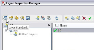
- This will open the Layer Standards dialog. You may find one or more Layer Standards already listed in the list box. One may have been imported, along with your default Layer Key Style, from the "auto-import" file specified on the Layering tab of the Drawing Setup dialog, or, if you started from a template file, the Layer Standards present may exist in the template file. We will ignore any in that list at this time, and select the New… button.

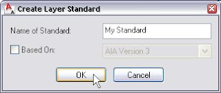
- The Create Layer Standard dialog will appear. Type a name for your standard in the Name of Standard edit box. For the purposes of this blog article, "My Standard" will be the name of the newly created standard (without the quotation marks). You will want to devise a more meaninful name for a Layer Standard you intend to use. Note the Based On toggle – if there is at least one Layer Standard defined in this file and you check this toggle, the dropdown list to the right will become active and you can choose from the available Layer Standards. A copy of the settings of the chosen Layer Standard will be made under your new name. Use this method if you want to modify an existing Layer Standard while retaining the original version. To start with a clean slate, leave the Based On toggle unchecked. The screen captures that follow will be based on starting from scratch. Select OK.
- The Layer Standards dialog will now include your new standard in the list box, and it will be selected. To edit any standard, select it from the list and choose the Edit… button.

- This will open the Layer Standard Properties dialog, which is where you will enter or modify all of the data associated with your standard. If it is not already selected, choose the Component Fields tab.
 As mentioned in the overview, Component Fields are the basic building blocks of a Layer Standard. Here is where you will set the rules for the Layer Standard being edited, based on the analysis of your layer naming convention. As shown above, when starting from scratch there is a Component Field named "Default value" with some initial values for the various properties associated with that Component Field. By clicking on the Field Name or any of the properties associated with it, you can edit the values. Some items must be selected from a popup menu, others will allow you to type in a value.
 - Click on the "Default value" name and change it to the name of your first Component Field. In my example here, I will be recreating the AIA Version 3 Layer Standard. The items identified in the breakdown of that Layer Standard above constitue the Descriptive Fields, which, as noted in the overview, are composed of one or more Component Fields. You will have to decide whether any of your Descriptive Fields require more that one Component Field. The first item in that standard is the "Discipline Designator," and it is composed of two Component Fields. This Descriptive Field can be either one or two characters in length; by making each character a separate Component Field, it makes it easier to make the second character optional, and, as we will see, creates a tiered hierarchy for the pre-entered values and descriptions, making it easier to scroll through the main (first character) disciplines, then expand that item if a sub-discipline (second character) is also desired. So my first Component Field is Discipline Designator 1, with the properties shown in the image below.
 Each Component Field has the following properties:
- Field Name: The name of the Component Field, which will be used to place it in a Descriptive Field when we get to the next tab.
- Optional: This determines whether or not this Component Field must appear in the eventual layer name. The Discipline Designator Descriptive Field is required to have at least one character, so the Discipline Designator 1 Component Field is required. Be careful with this one, as I have had problems in the past when I tried to make the final Descriptive Field from a Component Field that was not optional, following two other Descriptive Fields made from Component Fields that were optional. Layers that "met" the standard but which omitted the optional field were interpreted as not meeting it, and I believe this was because the final field, which had a different number of characters than the optional fields, was being misinterpretted as one of the optional fields. Whatever the cause back then, be certain to test your Layer Standard before deploying it, to be certain it works for all of the different layer names you expect to use and have recognized as complying with the standard.
- Max Width: Specify the maximum width of the Component Field here. Discipline Designator 1 has a maximum width of 1.
- Fixed Width: The width of Discipline Designator 1 Component Field is fixed.
- Wildcard: Any valid AutoCAD wildcard string can be used to limit the types of characters that can be used for the Component field. The popup list can be used to select Alpha, Numeric, Any or Other. Alpha and Numeric will generate the appropriate wildcard string based on the maximum width and whether the width is fixed to limit entered characters to alphabetic or numeric, respectively. Any will set the Wildcard to "*", allowing any character types. Other opens the Default value dialog box that allows you to enter a custom wildcard string. The "@" character in the wildcard for Discipline Designator 1 means that only alphabetic characters will be considered a match for this field. Multiple wildcard strings can be included, by separating them with commas. I suspect that the reason for the second string of "@@" – even though this field is fixed at one character in width - is that the Descriptive Field in which it appears includes another, optional, single-character, fixed width Component Field and that the two-character string is needed so that when both characters are used in the Descriptive Field, the layer is considered matching the wildcard. That is a guess on my part, but I did end up with a similar wildcard in the Layer Standard I put together, and I am certain I tried to get away with the equivalent of just "@". You can find a detailed description of the wildcard options supported by AutoCAD in the description of the wcmatch function in the AutoLISP Reference section of the Help. Access this from the main Help by selecting the Contents tab, expanding the AutoCAD Help node and selecting the AutoLISP, Visual LISP, and DXF node. Select the AutoLISP Reference link in the right pane to open the Developer Documentation to the AutoLISP Reference section. Select the "W" link in the right pane there, and then select the wcmatch link and scroll down to see the description of the various wildcard characters and see examples of their use.
- Match Description: If you want to limit values for this Component Field to those entered on the Edit Descriptions tab for the Descriptive Field to which the Component Field is included, then set this to Yes. I have had problems with setting this to Yes in the past, so be certain to test your Layer Standard if you choose to set this to yes. Discipline Designator 1 is set to No.
- Delimiter: You can specify a separator to divide Component Fields in this property. Supported delimiter characters are "$", "-" (hyphen), "_" (underscore) and "None" (all without the quotation marks). The specified delimiter appears BEFORE the Component Field to which it is assigned, so since the Discipline Designator 1 Component Field will be first in the layer name, the Delimiter is set to None.
- Default: Non-optional fields can have a default value specified. These values will be the initial values that appear when creating a layer name based on the Layer Standard. You can add default values to optional Component Fields, as the AIA Version 3 Layer Standard does, but default values will not show up as the initial value for any optional Component Field.
- Add additional Component Fields choosing the Add above the selected item button (upward pointing arrow icon) to add the new Component Field above the selected one or the Add below the selected item button (downward pointing arrow icon) to add the new one below the selected one.
 If you select a Component Field prior to selecting the Add above or Add below button, the new Component Field will be added immediately above or below the selected one and will inherit the properties assigned to the selected property. If no Component Field is selected, the new field wil be added at the top of the list or the bottom of the list, and will have the same properties as the initial "Default value" field had. While it may not actually matter, it is probably best to end up with the Component Fields in the order in which they will appear in the layer name, first at the top and last at the bottom. It will certainly make creating the Descriptive Fields easier, as the popup list from which you choose the Component Fields will list the Component Fields in the order they appear on the Component Field tab. Should you need to, you can select a Component Field and selected the Delete button to remove a Component Field and its settings from the list. The balance of the Component Fields for My Standard are shown in the image below.
 A side note for those who use the US National CAD Standard: when I set up my firm’s Layer Standard, I set the Major Field wildcard to "[~.][~.][~.][~.]" instead of "@@@@". Unless things were changed after Version 2 (I have not seen any of the more recent versions), while the description of the Major field stated that only alphabetic characters were permitted, one of the Major fields listed under the Fire Protection discipline – "CO2S – CO2 System" – included a numeric character. The period character in a wildcard string matches any character that is both non-alphabetic and non-numeric. The tilde character, when first in a wildcard string, matches any string that does not match the pattern that follows the tilde. Square brackets are used to enclose a list of characters that a single character can be. So any four-character string composed entirely of alphabetic or numeric characters will match my string, allowing "CO2S" to match.
 - Now we need to build the Descriptive Fields from the Component Fields. Select the Edit Descriptive Fields tab and verify that the name of your Layer Standard is shown in the Layer Standard dropdown list. You can assign up to eight Component Fields to a single Descriptive Field. When starting from scratch, there will be an initial "Default value" Descriptive Field, with no Component Fields assigned.

- Select the "Default value" Field Name, and enter the name of the first Descriptive Field in you layer naming convention. For my example, this will be "Discipline Designator". Now left click in the Component 1 column to the right of the Discipline Designator name, and choose the name of the Component Field that is to be assigned to this Descriptive Field from the context menu. In my example, this is the Discipline Designator 1 Component Field.
 To assign additional Component Fields to the same Descriptive Field, click in the next available component column and choose the appropriate Component Field. The Discipline Designator Descriptive Field in my example is composed of two Component Fields, so I added the Discipline Designator 2 Component Field to the Component 2 column.
 Notice that the Discipline Designator 1 Component Field is grayed out on the context menu. That item is no longer available because it has already been assigned. If you choose a Component Field in error, you can left click on it and choose Delete from the context menu to remove it.
 - The Delete, Add above and Add below buttons work the same way on the Edit Descriptive Fields tab as they do on the Component Fields tab. Use them to add Descriptive Fields to complete your layer naming comvention. On this tab, order does matter; the top Descriptive Field will appear first, with each Descriptive Field below following it, in order, with the bottom Descriptive Field at the end. The balance of the Descriptive Fields in my example have one Component Field each, and the name of each Descriptive Field matches that of the Component Field (with a space added before the numeral in the "Minor 1" and "Minor 2" Descriptive Fields. That is not necessary, but if there is a relationship between the names of the Component Fields and the Descriptive Fields, it will make remembering what your intent was easier should you need to come back to this some time in the future.

- You have now defined your Layer Standard, and can now add values and layer descriptions for each value for each of your Descriptive Fields, if desired. To do so, select the Edit Descriptions tab and verify that the name of your Layer Standard is shown in the Layer Standard dropdown list. Use the Field to Edit dropdown list to choose the Descriptive Field to which you will be adding values. The default values you provided on the Component Field tab should already appear in the edit box, but there will not be any layer description assigned to these.

- To edit an existing entry, select the entry and choose the Edit button. The Edit Description dialog will appear, and allow you to edit the Value and the layer Description, with the exception of any default values specified on the Component Fields tab, in which case you will only be able to edit the layer Description.
 The gray background on the Value edit box for the "A" Discipline Designator for my sample indicates that this is a default value. In order to edit this value, you would need to change it on the Component Fields tab. Note also the "+" sign in front of the "A" value in my example. As you may recall, the Discipline Designator Descriptive Field is composed of two Component Fields, Discipline Designator 1 and Discipline Designator 2, with the second part being optional. Descriptive Fields with two or more Component Fields assigned will be appear on the Edit Descriptions tab in a tree hierarchy. By selecting the "+" in front of the "A," the "A" heirarchy is expanded, revealing the next level down, and changing the "+" to a "-", allowing you to collapse that level.
 Because "D" was specified as the default value for the Discipline Designator 2 Component Field, a value of "AD" already appears here, waiting for a layer Description to be added, using the Edit button as before.
 Keep in mind that the layer Descriptions you enter for each Value can become part of the automatically generated Description that appears in the Layer Properties Manager for a created layer that complies with your Layer Standard, so make them descriptive, but keep them as brief as possible. Also note that while there is a hierarchy when multiple Component Fields are assigned to a single Descriptive Field, the layer Description is not hierarchical – for example, the "Architectural" entered for "A" does not automatically get applied to the layer Description of "AD"; that had to be typed in all over again. You may want to have a Notepad window open to allow you to copy and paste Description parts to avoid having to do a lot of repetitive typing.
 - To add a new Value, select the Add button. You will get the Add Description dialog, with an edit box for the Value of each Component Field assigned to the Descriptive Field being added, along with one for the layer Description. Enter value(s) as necessary to add the desired new value.
 If you intend to add multiple new Values, you can select the Apply button to register a particular Value and Description combination, then change the text entered in the edit boxes to suit the next Value and Description combination. This can also reduce the need for retyping if successive Values share some of the layer Description text. If any of the Component Fields are optional, you can clear any value in the associated edit box. In my example, this would allow you to enter a new Discipline-Designator-1-only value with a Description, in the same Add Description dialog use.
 You could also add a new Value that has a Discipline Designator 1 value that had not previously been entered along with a Discipline Designator 2 value, and a node showing only that new Discipline Designator 1 value will be created, but the Description for that would be an empty string.
 You can always go back after you are done adding descriptions and edit any such nodes to add a Description string to them. Note also that when a Descriptive Field contains more than one Component Field and you add a new value to the first Component Field, even if you also add values to the Component Field(s) that follow and choose Apply, only the node for the first Component Field will appear in the edit box; it will not be expanded. To expand the node, or simply to exit the Add Description dialog, select OK to accept the last value entered or Cancel to exit without adding the current values.
 - To add or edit Values for a different Descriptive Field, change to that Descriptive Field using the Field to Edit dropdown list at the upper right corner of the Edit Descriptions tab.
 How many Values and layer Descriptions to enter for each Descriptive Field is up to you. I would suggest adding all of those you expect to use for your firm’s standard layers for the Descriptive Fields that you include in the Description Specification (see below), so that you get "proper" layer descriptions built automatically for your firm’s standard layers. It will also make it easier for users to build new layers using officially sanctioned parts. If you entered "Yes" in the Match Descripition column any of your Component Fields, you will want to enter all allowed Values, as any omitted Values will not be able to be entered and have the layer accepted as complying with the Layer Standard.
 - The last thing to do before completing the first draft of your new Layer Standard is to select the Descriptive Specification tab and verify that the name of your Layer Standard is shown in the Layer Standard dropdown list.. This is where you indicate which Descriptive Fields contribute to the automatic layer description, and how that is formatted.
 There are two columns in the list box for this tab. The Prior Text column lets you add fixed text before a selected Descriptive Field, and the Field column allows to select from a popup list of the available Descriptive Fields. On this tab, you can use a given Descriptive Field more than once, but you do get a reminder in the popup list of which fields have already been used, as it is likely you would only want to use each one once. The Delete, Add above the selected item and Add below selected item buttons work the same way they do on the Component Fields and Edit Descriptive Fields tabs, but this time there is no default value if you started a new Layer Standard from scratch. To add the first Field, select either the Add above or Add below button.
 The first Descriptive Field in your Layer Standard will be initially selected in the Field column, but you can change it if you want by left clicking the Field name and choosing from the list. If you do not want any text added before this field, select the default "New" value in the Prior Text column and leave the column blank. Add additional Fields, with any desired Prior Text, as you see fit for your Layer Standard. In my example, all of the Descriptive Fields are included in the Descriptive Specification. No Prior Text is added before the initial Discipline Designator Field, but that Field is separated from the Major Field that follows by a space, a hyphen and a space. A comma and a space separate the Major Field from the Minor 1 Field, a single space separates the Minor 1 and Minor 2 Fields and a space, hyphen, space separates the Minor 2 Field from the Status Field. If you have Descriptive Fields that are composed of one or more optional Component Fields, and a particular layer name omits that Descriptive Field, then the Prior Text assigned to that Descriptive Field will not be included in the layer description.
- To see the Values, layer Descriptions and the Descriptive Specification in action, select OK in the Layer Standard Properties and Layer Standards dialogs to return to the Layer Properties Manager. Select the New Layer from Standard button on the Layer Properties Manager toolbar (eleventh from the left, between the New Layer and New Layer VP Frozen in All Viewports buttons) to open the New Layer From Standard dialog. At the top, make certainthat your new Layer Standard is selected as the Layer Standard. The list box should list your Descriptive Fields in the Field column, with the default values you specified for any non-optional fields in the Value column, and their associated layer Description strings in the Description column. The current Layer Name appears, with delimiters, if you specified any, in the Layer Name edit box, and the current Description that will be automatically associated with the layer will be shown in the Description edit box.
 Use the elipsis buttons at the right side of the Value column to change or add values to each Descriptive Field from a list of pre-specified values.
 Notice that as you add each pre-specified value, the description you associated with it gets added to the Description edit box, in the format you specified on the Descriptive Specification tab for your Layer Standard.
 A few sample layers, using the example Layer Standard I put together, can be seen in the image below, including a layer with a value for all of the Descriptive Fields and two that omit one or more optional fields.


