First Article in the Series: ACD-A Display System - Part 1, AutoCAD® BasicsPrevious Article in the Series: ACD-A Display System - Part 2, Big Picture OverviewBefore getting into the details of the Display System, a discussion of the ways in which display settings can be viewed and edited is in order. There are five ways to gain access to the Display System and its settings. Which one to use will depend on the task at hand and, where more that one will do, with your preferred means of working.
- Display Tab of the Drawing Setup Dialog.
- Display Manager.
- Display Properties Tab of a Style or Definition Properties Dialog.
- Display Properties Tab of the Object Display Dialog.
- Display Tab of the Properties Palette.
Display Tab - Drawing Setup Dialog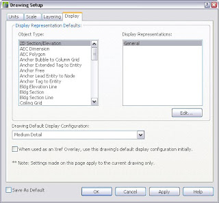
You may not have noticed this tab before, especially if you do not open this dialog very often now that you can set the drawing scale on the Drawing Window Status Bar. (You can access this dialog through the Open Drawing Menu - found on the left side of the Drawing Window Status Bar, the left pointing arrow in a circle icon, or from the Format pulldown menu.) Those who have been using AutoCAD
® Architecture long enough may recall that prior to Release 3, this was the only way to view and edit the Drawing Default display settings of any object, without having an instance or a style/definition of an object type in the drawing. The interface here is not as slick as the Display Manager, but if you find this more to your tastes, then by all means use it. Most, however, will consider this an interesting relic and will prefer to use the Display Manager for Drawing Default editing.
Display ManagerThe Display Manager gives you access to the Drawing Default settings for Display Representations, as well as to the settings for Display Representation Sets and Display Configurations. Anyone who is serious about making significant changes to the Display System needs to be very familiar with the Display Manager, which can be opened by choosing the Display Manager... item on the Format pulldown menu.
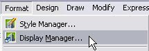
It is also available via a button on the CAD Manager toolbar button if you have the CAD Manager CUI loaded as a partial CUI.
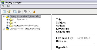
The Display Manager Dialog has File and Edit pulldown menus, a tool bar, two main panes, left and right, and the usual OK, Cancel, Apply and Help buttons. Most of the action will take place in the left and right panes. The left pane is a tree view pane, that allows you to navigate the various parts of the Display System. Since the 2006 release, all open drawings are shown in the left pane, and you can use the Open toolbar icon or File > Open drawing... from the pulldown menus to open a file in Display Manager that is not open in AutoCAD Architecture. Earlier versions will only give you access to the display settings of the file that was currently active when the Display Manager was opened.
Configurations: Use the left pane to find the part of the Display System you want to examine or edit, then view the settings and make any desired edits in the right pane. The information shown in the right pane will vary, depending upon what is selected in the left pane. For example, selecting the Configurations node for a particular drawing shows a matrix in the right side with the Display Configurations (Configurations) in that drawing listed in the rows and the Display Representation Sets (Sets) in that drawing listed in the columns. An icon appears in the matrix to indicate that a particular Set is active in a particular Configuration. The icon displayed varies with the view direction to which the Set is assigned. A "see-through" cube indicates that the Set is assigned to the Default view direction, while a cube with a "solid" top face indicates the Set is assigned to the Top view direction. A key of all of the icons used for Configurations in the Display Manager can be found in the 2008 Help, by navigating through the following on the Contents tab: AutoCAD Architecture 2008 Help > AutoCAD Architecture User's Guide > Workflow and User Interface > Display System > The Display Manager > Viewing Display Configurations (other versions likely have a similar page).
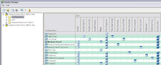
Expanding the Configurations node in the left pane will reveal a list of the Display Configurations in that drawing (the same ones that were listed in the rows of the matrix above). Note that one of these will be in
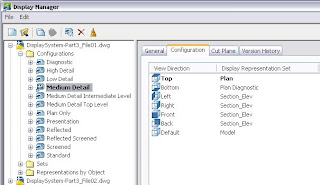
BOLD type, indicating that it is the currently active Display Configuration. This graphic convention carries through for Display Representation Sets, making it easy to know whether the edits you are making will affect the current display. Selecting one of these will display several tabs in the right pane. The General tab displays the Configutation name, description and allows for adding notes, if desired. The Configuration tab shows a list of the standard view directions and the Display Represenation Set assigned to that view direction for that Display Configuration, if any. The Display Representation Set assigned to the Default view direction is used for all view directions that are not one of the six standard orthogonal view directions, as well as for any of those six that is not assigned a Display Representation Set.
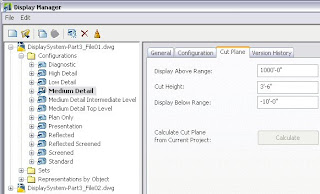
The Cut Plane tab allows you to set the cut plane height for the Display Configuration, as well as the above and below ranges.
The Version History tab is used in conjunction with Project Standards (a subfeature of the Drawing Management/Project Navigator feature). Expanding a specific Display Configutation node in the left pane will show a list of the Display Representation Sets assigned to that Configuration. Selecting one of these displays the same set of tabs that display when selecting a Display Representation Set under the Sets node (shown below). Just keep in mind any changes made here will affect all uses of that Display Representation Set, not just its use in this particular Display Configuration.
Sets: Selecting the Sets node in the left pane displays a list of the Display Representation Sets defined in that drawing, with the description of each and the ability to set whether or not a give Display Representation Set should be ignored during Standards Synchronization.
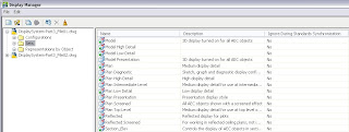
Expanding the Sets node in the left pane displays a list of the Display Representation Sets (
BOLD type indicated the currently active one). An explanation of the icons displayed next to the Display Representation Sets can be found in the 2008 Help: AutoCAD Architecture 2008 Help > AutoCAD Architecture User's Guide > Workflow and User Interface > Display System > The Display Manager > Viewing Display Sets. Selecting one of the Sets displays several tabs in the right pane. The General tab offers the same options as the General tab for Configurations. The Display Represenation Control tab, which offers a matrix of Objects on the rows and Display Representations on the columns. On each object row, a toggle appears in the column for every Display Representation that is defined for that object type. If a check mark appears in that toggle, then that Display Representation for that object type is active in the selected Display Representation Set. A left mouse click on a toggle will change the status - checked (active) or unchecked (inactive). A right mouse click on a toggle offers a context menu with three options: Select All (make all Display Representations for that object type active), Clear All (make all Display Representations for that object type inactive) and Edit... (edit the display settings for that particular Display Representation/Object Type. Display Representations can also be edited as noted below under the Representations by Object node; keep in mind any edits made here will affect all uses of that Display Representation.
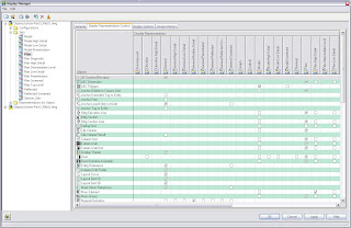
The Display Options tab offers the ability to fine-tune your display settings based on Classifications (if any are defined in the current drawing) and control live sections and materials.
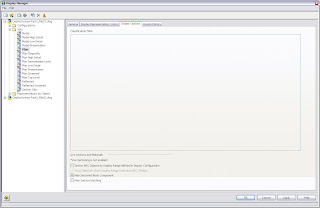
The Version History tab serves the same purpose as it does for Configurations.
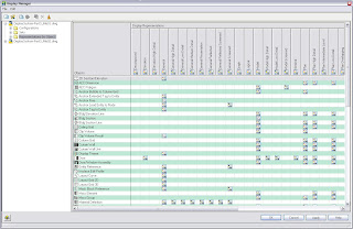
Representations by Object: Selecting the Representations by Object node in the left pane displays a matrix of Objects on the rows and Display Representations in the columns. In this matrix, an icon is displayed where the Display Representation of a given column is defined for the object type of a given row. An explanation of these icons (also used in the list of Display Representations below each object type - see below) can be found in the 2008 Help here: AutoCAD Architecture 2008 Help > AutoCAD Architecture User's Guide > Workflow and User Interface > Display System > The Display Manager > Viewing Display Representations. Right clicking on an icon displays a context menu with various options, including Delete (only works if the Display Representation for that object type is not referenced by a Display Representation Set), several options related to Project Standards (these may be grayed out if the selected drawing is not part of the current project, or a project is not set current) and Edit..., which allows you to edit that Display Representation for the given object type.
Expanding the Representations by Object node in the left pane shows a list of the AEC object types in the drawing that interact with the Display System. Selecting one of these shows a matrix in the right pane, with a list of the Display Representations defined for that object type on the rows and the Display Representation Sets defined in that drawing on the Columns. A toggle occurs at each row/column intersection; a check mark indicates that the Display Representation of a given row is active for the Display Representation Set of a given column. A left mouse click changes the toggle status. A right click on a toggle displays a context menu that offers several choices: Duplicate (make a copy of the Display Representation), Delete (the Display Representation, will only work if it is not referenced by a Display Representation Set), Rename (only available for Display Representations that are not hard coded into the program), several Project Standards options (see note above under Sets), Select All (set Display Representation active for all Sets), Clear All (set Display Representation inactive for all Sets) and Edit Drawing Default... (edit the display settings for the Display Representation).
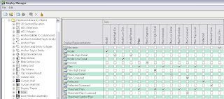
Expanding the object node in the left pane displays a list of Display Representations defined for that object in that drawing. Selecting one of the Display Representations in the left pane displays tabs in the right pane related to the display settings for the selected object type. Some object types, such as Anchor Free, do not have any user-editable display settings, and the right pane will remain blank when selecting a Display Representation under these (note the grayed-out Display Representation icon in the left pane in these cases). We will get into more detail on the various tabs and settings in a future article.
 Display Properties Tab - Style/Definition Properties Dialog
When editing a style or definition, the Display Properties tab will give you access to the display settings for that object type. On this tab, you can edit the Drawing Default level settings, if the override column toggle for that Display Representation is not checked. If the toggle is checked, or you add a check to that toggle, you can edit/create a style-level override for that style/definition/Display Representation.
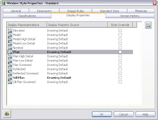
You can edit the display settings by selecting a Display Representation and then selecting the edit button in the upper right of the dialog. Setting an override will also open the Display Properties dialog for that Display Representation.
Display Properties Tab - Object Display DialogSelecting an object in your drawing and right clicking displays a context menu which includes Edit Object Display... as an option.
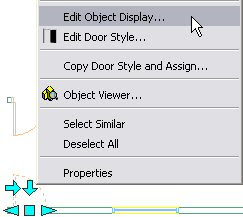
Choosing this opens the Object Display Dialog; the Display Properties tab offers the same access to the Drawing Default display settings as seen when editing a style/definition, only here any override is applied at the object level, so it only affects the selected object.
 Display Tab - Properties Palette
This is the new kid on the block, and it gives you the option to see changes "live". It also allows you to select the component you want to change in the drawing, without having to wade through a lot of dialogs to get to the setting you want. That can be something of a double-edged sword, however, in that the ease of making changes can result in ill-considered changes that could make a mess of the display settings in relatively short order, particularly when used by someone who does not fully understand the Display System. For that reason, I am going to defer any detailed discussion of this method until after I have covered the Display System in detail, using the methods of access noted above.
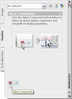
You can also initiate the select component feature by selecting any object, right clicking and choosing Select Component from the context menu. You are not restricted to selecting components of the originally selected object.

 Right clicking on the tool and choosing Properties... from the context menu...
 ...opens the Tool Properties dialog, as shown below. This tool is a "Tag" type tool that currently does not add any Property Sets other than those referenced in the Schedule Tag, since the Property data property is empty.
 If you left click on the Type property, you will get a pulldown menu with two choices: Tag and Property set data, as seen below. Change this from Tag to Property set data...
 to have the tool attach Property Sets without adding a tag.
 The tool you copied may point to a source file other than the one where your properties are kept. If so, simply left click on the Property def location property, and choose Browse... from the pulldown list.
 This will open a standard file selection dialog that will allow you to navigate to the folder holding your source file and select that source file. With the proper source file chosen, left click on the Property data property, and choose the property or properties you wish to have the tool add from the Add Property Sets worksheet that displays. You can choose from both object-based and style-based Property Sets, keeping in mind that if you add a style-based set to an object, all objects of the same style will also have that Property Set added.
 Select OK to register your choice(s), and then OK again to save the changes you made to your tool. Its as simple as 1, 3, 2 - and your tool is good to go. For a truly professional look, you may want to create a custom image file for your Property Set tool and add that to the tool (right click on the image in the Tool Properties dialog and choose Specify Image... from the context menu to specify the image file you created). Unlike tools that reference visible drawing objects, there is no "automatic" image for a Property Set only tool; the tool will retain the original image from the tag you copied unless you manually replace it with another image.


