Just as a typical automobile driver needs to know little about the modern internal combustion engine and how it interfaces with the rest of the automobile in order to be able to drive, the typical AutoCAD® Architecture end user does not need to have a deep understanding of the Display System. When working with a properly set up system, the end user only needs to select the correct Display Configuration and view direction, and everything should display and plot correctly.
On the other hand, if the out-of-the-box settings do not quite meet your firm's requirements and you are the one tasked with doing what needs to be done to ameliorate the situation, unless you have the power to change your firm's requirements to match the out-of-the-box settings, you will need a good understanding of the Display System. This purpose of this series of blog articles is to provide that understanding. The Display System, like most powerful computer features, has a level of complexity that tends to overwhelm people the first time they take a look under the hood. Rather than dive into the details and risk getting lost, this installment will provide a "big picture" overview of the Display System. Future articles will look at the components and their use in more detail; come back here when you need to get your bearings and see how that detail relates to the overall system.
Display System Components
There are three primary parts to the Display System:
- Display Configurations
- Display Representation Sets
- Display Representations
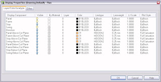
Display Represenations are the building blocks of the Display System. A Display Representation holds the instructions for how a particular object type is to display, when that Display Representation is active. While there are a few, non-graphical object types that do not have editable settings, such as Anchor Free, most AEC object types have at least one editable Display Representation. Within each Display Representation, there is at least one "component" to which display settings can be assigned. Components behave similarly to nested objects within a block definition.
Example of Display Representation Settings -
Plan Display Representation for Doors
Plan Display Representation for Doors
 You will need a separate Display Representation for each different way you want a particular object type to appear.
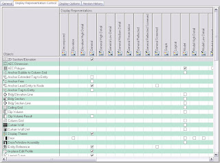
Display Representation Sets are collections of Display Representations, usually for multiple object types, that are intended to be seen (turned on or active) at the same time. At any given time, only one Display Representation Set is active; AutoCAD Architecture uses the settings in the Display Representations that are active in the active Display Representation set to determine how to display and plot AEC objects.
Example of Display Representation Set -
Partial View of Out-of-the-Box Plan Display Representation Set
Partial View of Out-of-the-Box Plan Display Representation Set
 Check marks in the matrix represent an active Display Representation Set for a particular AEC object.
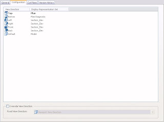
Display Configurations are what the user chooses and are where the view-dependent nature of the Display System is set. One or more Display Representation Sets are assigned to various view directions in the Display Configuration. While it is possible to assign just one Display Representation Set to a Display Configuration (to the Default view direction, resulting in most objects displaying the same way for all view directions), most Display Configurations have separate Display Representation Sets for the Top (plan), Bottom and the four "elevation" view directions (Front, Back, Left and Right), leaving a three-dimensional or "model" Set assigned to the Default view direction, to cover any non-orthogonal views. This is how AutoCAD Architecture is able to change the way objects display when the view direction changes, even though the Display Configuration remains the same.
Example of Display Configuration -
Out-of-the-Box Medium Detail Display Configuration
Out-of-the-Box Medium Detail Display Configuration

Levels of Display Contol
The Display System provides three levels at which Display Representation settings can be made:
- Drawing Default
- Style-level Override
- Object-level Override
When an override is applied, all settings for that Display Representation are overriden, even those that remain unchanged from levels lower in the hierarchy. This means that if you later decide to change a Drawing Default setting, that change will not be reflected in objects controlled by a Style-level or Object-level Override, unless you edit the override(s) and make the change there, also. For this reason, best practice is to minimize the use of Style-level Overrides and to avoid Object-level Overrides whenever possible.
Next Article in the Series: ACD-A Display System - Part 3, Viewing and Editing Display Settings
No comments:
Post a Comment