In response to a thread in the Autodesk Architectural Desktop 2006 Discussion Group, I posted a sample file and explanation of one way to take one of the out-of-the-box wall styles that has an endcap, and modify both the wall style and create a new endcap for the modified style. The example shows converting a wall style with 5/8" GWB on a metal stud to 1/2" GWB on the same metal stud.
The original poster managed to resolve his problem using in-place editing; my post explains how to use the WallEndcap command to generate the defining polylines of an existing Wall Endcap Style, then use those to create a new Wall Endcap Style for the modified wall style.
August 07, 2005


August 03, 2005
Schedule Column Loss in "Old" Drawings
Just a quick reminder, prompted by me running into this issue face-first today. If you have an "older" drawing that has a previous version of a Property Set Definition using the same name as your current version, but that may be missing a property or two [or may use a now changed name for the property] that is used for a column in a Schedule Table Style, when you add the current Schedule Table Style to the file, it will not import the current version of the Property Set Definition, as it already exists in the drawing. All columns that reference properties that are missing, or going by an old name, will magically disappear from the Schedule Table Style.
Use Style Manager to manually update the old Property Set Definitions first, then bring in the Schedule Table Style, to avoid column loss. Those using ADT 2006 could make use of the new Standards features to update older drawings that are made part of a project.
Use Style Manager to manually update the old Property Set Definitions first, then bring in the Schedule Table Style, to avoid column loss. Those using ADT 2006 could make use of the new Standards features to update older drawings that are made part of a project.
August 01, 2005
Door/Window Assembly With Half-Height Sidelight
In a post to the AUGI ADT General Forum, I attached a sample file that demonstrates how you can create a Door/Window Assembly that has a Door with a "half-height" sidelight adjacent to it - that is, the top of the sidelight frame aligns with the top of the door frame, but the sidelight does not continue all of the way to the floor.
I started out by copying the out-of-the-box Hinged - Single door style, renaming the copy to Hinged - Single - NoFrame and setting the frame width to 0", to create a frameless door style for use as an infill in a Door/Window Assembly. Then I created a new Door/Window Assembly style called Door - Half-Height Sidelight and set up the following elements:
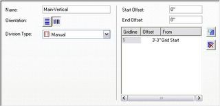
Main-Vertical Division
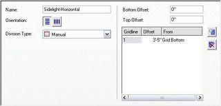
Sidelight-Horizontal Division
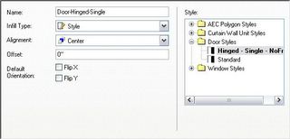
Door-Hinged-Single Infill
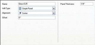
Glass-0.25 Infill
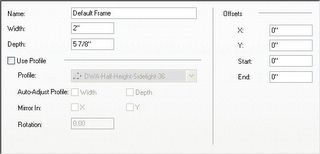
Default Frame Frame
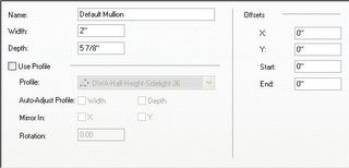
Default Mullion Mullion
The out-of-the-box Doors & Windows.Glazing.Glass.Clear material was assigned to the Glass-0.25 Infill; the Default Frame and Default Mullion components had the Doors & Windows.Metal Doors & Frames.Aluminum Frame.Annodized.Dark Bronze.Satin material assigned [mostly because it came in with the Hinged - Single Door, which has the Doors & Windows.Wood Doors.Ash material assigned to the door panel].
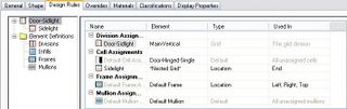
I renamed the Primary Grid to Door-Sidlight, managing to omit the "e" in "Sidelight" in my haste. The assignments for this grid are shown below. Note that a nested grid is assigned to the End cell. This "New Nested Grid" was renamed Sidelight [and spelled correctly, this time]. Also note that Default Frame is only assigned to the left, right and top - the bottom frame is omitted, as we do not want one at the door and the sidelight does not extend to the floor.
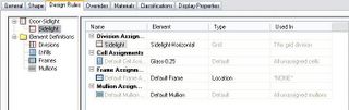
The Sidelight Grid assignments were made as shown below.
A 6'-6" wide x 7'-2" high instance of this Door Window Assembly style was inserted in an out-of-the-box Stud-3.625 GWB-0.625 Each Side wall. I changed to a SE Isometric view and turned on the infill markers by selecting the Door/Window Assembly, right clicking and choosing Infill>Show Markers from the context menu. With the Door/Window Assembly still selected, I right clicked and chose Infill>Override Assignment... from the context menu, and then selected the infill marker in the lower half of the sidelight cell. I chose the Remove Infill and Frames option in the Infill Assignment Override dialog and selected OK. I then transferred the Design Rules to the object [select Door/Window Assembly, right click, choose Design Rules>Transfer to Object] and then transferred them back to the style [with Door/Window Assembly still selected, right click, choose Design Rules>Save to Style... and then check Transfer Infill Overrides to Style in the Save Changes dialog and click OK]. These overrides are now part of this style and will be applied to all instances of this style. This style is illustrated on the left side of the image below. Notice that even though the bottom cell of the sidelight and its frame are turned off, the wall does not fill in below the sidelight. If you are only interested in a plan view of this assembly, you are essentially done [depending upon the cut plane height and the height at which you set the bottom mullion of the sidelight, you may need to add a manual cut plane to see the mullion]. But if you want to generate an elevation or do a 3D view/rendering, you will need to do one more thing to get the results shown on the right Door Window Assembly.
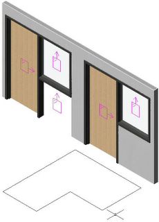
SE Isometric View ;
In order to get the wall to fill in under the sidelight, you will need to create a profile that describes the outline of the outer edge of the frames/mullions and the floor line, then assign it to the style. Draw a LWPOLYLINE in the desired shape. In the Style Manager, create a new Profile [under Multi-Purpose Objects], give it the desired name, then right click the profile name and choose Set From... on the context menu. Select the polyline and choose an insertion point; I chose the lower left corner [door side]. Note that assigning a profile will effectively fix the dimension of the Door/Window Assembly. You can change the width, and the profile will be scaled to match, but you will get undesirable 3D results - as the width is made less than that used when drawing the profile, the door mullion below the sidelight will start to disappear, and eventually the door will also be notched. As the width grows larger than the original profile width, the wall infill will fall short of the door mullion below the sidelight. In the sample file, I created a copy of the original style, then assigned the 6'-6" wide profile to it. This would allow me to make additional copies of the original style and assign profiles with different widths, if needed.
I started out by copying the out-of-the-box Hinged - Single door style, renaming the copy to Hinged - Single - NoFrame and setting the frame width to 0", to create a frameless door style for use as an infill in a Door/Window Assembly. Then I created a new Door/Window Assembly style called Door - Half-Height Sidelight and set up the following elements:
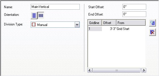
Main-Vertical Division

Sidelight-Horizontal Division
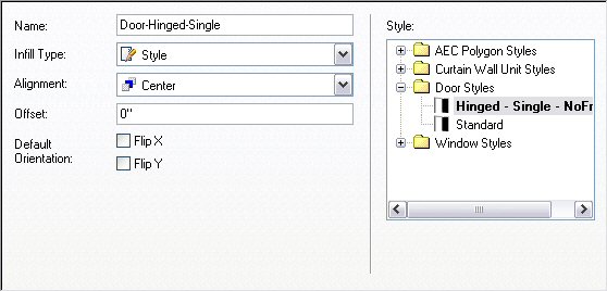
Door-Hinged-Single Infill
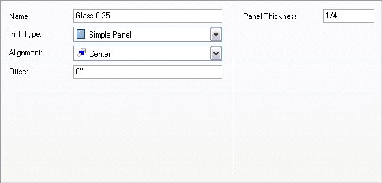
Glass-0.25 Infill
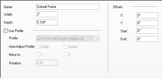
Default Frame Frame
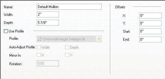
Default Mullion Mullion
The out-of-the-box Doors & Windows.Glazing.Glass.Clear material was assigned to the Glass-0.25 Infill; the Default Frame and Default Mullion components had the Doors & Windows.Metal Doors & Frames.Aluminum Frame.Annodized.Dark Bronze.Satin material assigned [mostly because it came in with the Hinged - Single Door, which has the Doors & Windows.Wood Doors.Ash material assigned to the door panel].
I renamed the Primary Grid to Door-Sidlight, managing to omit the "e" in "Sidelight" in my haste. The assignments for this grid are shown below. Note that a nested grid is assigned to the End cell. This "New Nested Grid" was renamed Sidelight [and spelled correctly, this time]. Also note that Default Frame is only assigned to the left, right and top - the bottom frame is omitted, as we do not want one at the door and the sidelight does not extend to the floor.

The Sidelight Grid assignments were made as shown below.

A 6'-6" wide x 7'-2" high instance of this Door Window Assembly style was inserted in an out-of-the-box Stud-3.625 GWB-0.625 Each Side wall. I changed to a SE Isometric view and turned on the infill markers by selecting the Door/Window Assembly, right clicking and choosing Infill>Show Markers from the context menu. With the Door/Window Assembly still selected, I right clicked and chose Infill>Override Assignment... from the context menu, and then selected the infill marker in the lower half of the sidelight cell. I chose the Remove Infill and Frames option in the Infill Assignment Override dialog and selected OK. I then transferred the Design Rules to the object [select Door/Window Assembly, right click, choose Design Rules>Transfer to Object] and then transferred them back to the style [with Door/Window Assembly still selected, right click, choose Design Rules>Save to Style... and then check Transfer Infill Overrides to Style in the Save Changes dialog and click OK]. These overrides are now part of this style and will be applied to all instances of this style. This style is illustrated on the left side of the image below. Notice that even though the bottom cell of the sidelight and its frame are turned off, the wall does not fill in below the sidelight. If you are only interested in a plan view of this assembly, you are essentially done [depending upon the cut plane height and the height at which you set the bottom mullion of the sidelight, you may need to add a manual cut plane to see the mullion]. But if you want to generate an elevation or do a 3D view/rendering, you will need to do one more thing to get the results shown on the right Door Window Assembly.
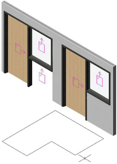
SE Isometric View ;

In order to get the wall to fill in under the sidelight, you will need to create a profile that describes the outline of the outer edge of the frames/mullions and the floor line, then assign it to the style. Draw a LWPOLYLINE in the desired shape. In the Style Manager, create a new Profile [under Multi-Purpose Objects], give it the desired name, then right click the profile name and choose Set From... on the context menu. Select the polyline and choose an insertion point; I chose the lower left corner [door side]. Note that assigning a profile will effectively fix the dimension of the Door/Window Assembly. You can change the width, and the profile will be scaled to match, but you will get undesirable 3D results - as the width is made less than that used when drawing the profile, the door mullion below the sidelight will start to disappear, and eventually the door will also be notched. As the width grows larger than the original profile width, the wall infill will fall short of the door mullion below the sidelight. In the sample file, I created a copy of the original style, then assigned the 6'-6" wide profile to it. This would allow me to make additional copies of the original style and assign profiles with different widths, if needed.
AUGI ATP Courses for August 2005
There are three classes this month, starting on August 8. Pre-registration has been re-instituted, so you can sign up for classes today. If you are already an AUGI member, login to the website, click on Education in the link bar below the logo and follow the ATP links at the left side. If you are not a member - now is a perfect time to join. Membership is free, as are the ATP courses.
ATP085 Access and AutoCAD: A Wedding Invitation
Category: AutoCAD
Course Title: ATP085 Access and AutoCAD
Level: Beginner
Instructor: Eric Wing
Course Start: Monday, August 8, 2005
Status: Open for Registration
It’s true! Access and AutoCAD were MADE for each other. There’s always been a reserved space in AutoCAD’s “heart” for Microsoft’s Access database. Bringing together the compatible components of these two programs, this course will start with creating an Access database (.mdb) with simple tables, queries, forms and reports. The student will then use this database as a data source in AutoCAD. You can put your brain on the shelf for this one because it’s easy!
ATP086 ObjectARX for Dummies
Category: Programming
Course Title: ATP086 ObjectARX for Dummies
Level: Advanced
Instructor: Fernando Malard
Course Start: Monday, August 8, 2005
Status: Open for Registration
Start to program easily with ObjectARX through simple and direct examples. The course will cover the minimum application overview with practical examples and most common procedures. If you always dreamed of creating an ObjectARX application but never had the courage to face the huge documentation, this class is perfect for you. This course will cover: ObjectARX Application basics, AutoCAD database basics, user interface basics, custom entities basics, custom objects basics and notification basics.
ATP087 Collaborating with AutoCAD and DWF Composer
Category: AutoCAD
Course Title: ATP087 AutoCAD's DWF Composer
Level: All Levels
Instructor: David Cohn
Course Start: Monday, August 8, 2005
Status: Open for Registration
Do you need to exchange drawings and collaborate with others who don’t use AutoCAD? Learn how to publish AutoCAD drawings as multi-sheet DWF files and then collaborate using Autodesk DWF Composer. This class covers creating DWF files; using DWF Composer to view, measure and mark up those DWF files; and then using AutoCAD’s Markup Set Manager to view and respond to those markups in a seamless collaboration process.
ATP085 Access and AutoCAD: A Wedding Invitation
Category: AutoCAD
Course Title: ATP085 Access and AutoCAD
Level: Beginner
Instructor: Eric Wing
Course Start: Monday, August 8, 2005
Status: Open for Registration
It’s true! Access and AutoCAD were MADE for each other. There’s always been a reserved space in AutoCAD’s “heart” for Microsoft’s Access database. Bringing together the compatible components of these two programs, this course will start with creating an Access database (.mdb) with simple tables, queries, forms and reports. The student will then use this database as a data source in AutoCAD. You can put your brain on the shelf for this one because it’s easy!
ATP086 ObjectARX for Dummies
Category: Programming
Course Title: ATP086 ObjectARX for Dummies
Level: Advanced
Instructor: Fernando Malard
Course Start: Monday, August 8, 2005
Status: Open for Registration
Start to program easily with ObjectARX through simple and direct examples. The course will cover the minimum application overview with practical examples and most common procedures. If you always dreamed of creating an ObjectARX application but never had the courage to face the huge documentation, this class is perfect for you. This course will cover: ObjectARX Application basics, AutoCAD database basics, user interface basics, custom entities basics, custom objects basics and notification basics.
ATP087 Collaborating with AutoCAD and DWF Composer
Category: AutoCAD
Course Title: ATP087 AutoCAD's DWF Composer
Level: All Levels
Instructor: David Cohn
Course Start: Monday, August 8, 2005
Status: Open for Registration
Do you need to exchange drawings and collaborate with others who don’t use AutoCAD? Learn how to publish AutoCAD drawings as multi-sheet DWF files and then collaborate using Autodesk DWF Composer. This class covers creating DWF files; using DWF Composer to view, measure and mark up those DWF files; and then using AutoCAD’s Markup Set Manager to view and respond to those markups in a seamless collaboration process.
July 26, 2005
Beau Turner on ADT - Mass Tool Palette Generation
Beau Turner has posted an article in his blog on how Autodesk Architectural Desktop 2006 makes generating multiple tools/palettes from a source file much easier than previous versions, where tools were created one at a time.
July 16, 2005
WxH Formula For Windows
In Archtitectural Desktop, doors have special automatic properties that combine the width, height and thickness - or just width and height - into one property so you can display that information in one column of your schedule. Windows, however, do not offer a similar option. Those working with imperial units [feet and inches] may have found that trying to combine width and height properties to which imperial architectural formatting has already been applied in a formula property is not as easy as you might at first think, due to the fact that the symbol for inches is also the delimeter used to represent the extents of strings.
It is possible to create your own W x H formula property for windows, but it will require a little more work that simply combining two pre-formatted strings. I have posted a sample file to the "PSD-Window Size WxH" thread in the Autodesk Architectural Desktop 2005 Discussion Group. This file has a Property Set Definition called WindowObjectsWxH that has two formula properties - one that displays feet, inches and decimal inches and one that displays feet, inches and fractions of an inch, rounded to the nearest eighth of an inch. Each formula uses variables to store the results of the calculations that convert the unformatted inch values into feet, inches and the selected fractional inch option, then puts them all together at the end, using Chr(34) to generate the inch marks.
If you are interested, be certain to get the HxWtest-Imperial_rev1.zip file rather than the first file I posted, as that has corrections and improvements to the feet, inches and decimal inches formula, as noted in the post.
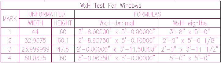
Here is a screen capture of a schedule table that shows the unformatted height and width values for four sample windows, and the way each of the two formulas displays those values.

It is possible to create your own W x H formula property for windows, but it will require a little more work that simply combining two pre-formatted strings. I have posted a sample file to the "PSD-Window Size WxH" thread in the Autodesk Architectural Desktop 2005 Discussion Group. This file has a Property Set Definition called WindowObjectsWxH that has two formula properties - one that displays feet, inches and decimal inches and one that displays feet, inches and fractions of an inch, rounded to the nearest eighth of an inch. Each formula uses variables to store the results of the calculations that convert the unformatted inch values into feet, inches and the selected fractional inch option, then puts them all together at the end, using Chr(34) to generate the inch marks.
If you are interested, be certain to get the HxWtest-Imperial_rev1.zip file rather than the first file I posted, as that has corrections and improvements to the feet, inches and decimal inches formula, as noted in the post.
Here is a screen capture of a schedule table that shows the unformatted height and width values for four sample windows, and the way each of the two formulas displays those values.
Unformatted Properties and Numeric Precision
The out-of-the-box Standard Property Data Format does not add any special formatting to a number [prefix, suffix or architectural/engineering imperial formatting], as noted in a previous blog article. Be aware, however, that it also rounds off values to three decimal places, so any values you bring into your formula from properties using the Standard Property Data format will start out rounded off that way. That may be sufficient accuracy for your task, but when it is not, simply copy the Standard Property Data Format and, in the copy, increase the Precision to the number of places you need. The image below shows a Property Data Format I set up and named Standard-8, using the maximum eight decimal place precision.

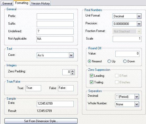
My Custom Standard-8 Property Data Format
July 14, 2005
AUGI CAD Camp Update

Registration is now open for the AUGI CAD Camps in Orange County, CA; Salt Lake City, UT; Columbus, OH; and Toronto, ON.
In addition to these camps noted in a previous blog article
August 16th: Orange County, CA USA (registration open)
August 23rd: Salt Lake City, UT USA (registration open)
August 30th: Toronto, ON Canada (registration open)
September 13th: Paramus, NJ USA (registration opens 7/17)
September 15th: Cleveland, OH USA (registration opens 7/17)
September 27th: Jacksonville, FL USA (registration opens 8/1)
September 29th: Boston, MA USA (registration opens 8/1)
the following dates have also been scheduled:
August 25th: Columbus, OH USA (registration open)
September 22nd: Kansas City, MO USA (registration opens 7/25)
October 18th: Birmingham, AL USA (registration opens 8/22)
October 25th: Denver, CO USA (registration opens 8/29)
July 11, 2005
Chris Yanchar Posts ADT 2006 New Features Presentation
Chris has posted the PowerPoint and sample files that Bill Glennie and Chronis Loulakis presented at TechCamp 2005 in an article in his blog. The presentation highlights the new features in Autodesk Architectural Desktop 2006.
July 09, 2005
Structure/Flow in Formula Properties: Select Case/Case/Case Else/End Select Construct
INTRODUCTION
Here is another VBScript construct that you can use to change the RESULT of your formula based on the current value of a VBScript expression. The expression can be the current value of a property from a Property Set attached to the same object, a variable that you defined earlier in the formula [perhaps by manipulating the values of one or more properties] or a VBScript statement [perhaps operating on a property or a previously defined variable]. The Select Case construct allows you to specify multiple different actions based on the value of that expression. A Select Case construct can be much easier to set up and maintain than a complex If/Then/ElseIf/Else/End If construct, particularly if you start nesting additional If/Then/ElseIf/Else/End If constructs, and it does not require evaluating the expression for each conditional statement. As with the If/Then/ElseIf/Else/End If construct http://architects-desktop.blogspot.com/2005/07/structureflow-in-formula-properties.html, each branch of the Select Case construct must end in assigning the formula properties final value to “RESULT”. Depending upon your needs, the RESULT statement could be after the end of the Select Case block of code, which may simply set other variables to appropriate values. But many times you will set a RESULT in the action statements associated with each case; when doing so, be certain to include a RESULT statement in the action statements for each case branch.
SYNTAX
You start out by giving the expression, then list various possible values and the actions to take when the expression evaluates to that particular value. You can optionally include a Case Else statement to specify actions to be taken if none of the listed cases matches the current value of the expression. It is good programming practice to include a Case Else statement, even if you are one-hundred percent certain that you have covered every possible value in the Case statements, even if all you do there is assign a value that indicates an unexpected even has occurred. Seeing that value will let you know that somehow, the expression has taken on an unexpected value and make debugging your formula that much easier.
The basic structure of the Select Case construct is shown below. Explanations of the italicized items are listed below the structure; items shown in blue and enclosed by square brackets are optional. You can nest Select Case constructs within each other by including one in the action statements to be evaluated when a particular Case is true.
This required element is the value that is compared to the values specified for each Case. It can be an actual value [e.g. 23.0, “String”], a variable [the current value assigned is used], a math or comparison expression [11.0 + 12.0, x > 23.0] or a user-defined or VBScript function that returns a value.
expressionlist1
expressionlist2
These are the values that are compared to the expression; you must provide at least one value for each Case you include in your Select Case construct. You can list multiple values by separating each value by a comma. Each value can be any of the types listed for the expression. When one of these values matches the value of the expression, the action statements associated with that Case are executed. You may have any number of Case blocks of code.
actionstatements1
actionstatements2
One or more statements to be executed when the value for a particular Case matches that of the expression.
elseactionstatements
One or more statements to be executed if none of the Case values match the expression value.
EXAMPLES
This example is based on the way my firm handles door frame types and materials. We designate each frame type with a letter; each type has a particular material associated with it. There are a number of “office standard” types and the letters assigned to these types are reserved for that type; custom types for a particular project never make use of the letter designation assigned to an office standard type. There are certain door types that can have more than one frame type associated with it. Rather than have a separate door style for each door type/frame type combination, our frame type property is in an object-based property set. To avoid have the user have to enter both the frame type designation and the material for office standard frame types, a formula property using a Select Case construct is used to automatically assign the correct material type. A manual property is included in the property set so that the user can specify the material for custom frame types. The Case Else block of code is used to read in and return this value only when the frame type designation is not an office standard one. The following formula shows an example of this concept. It assumes the following:
Anyone familiar with the VBA implementation of the Case Select construct should note that VBScript does not support the To or Is keywords in an expressionlist. These are handy for specifying a range of values to compare to the expression, but are not available in a formula property. One way around this is to set the expression to true or false, using the VBScript constants vbTrue or vbFalse respectively. You can find these in 2006 in the “Insert VBScript code: “ pane in the lower right of the Formula Property Definition dialog, under Constants > Tristate. Then set up your expressionlists with comparison statements that evaluate to true or false. The following example is fairly simple, and could just as easily have been done with an If/Then/Elseif/Else construct. But if you had many ranges, with different actions to take for each range, a Select Case construct may be easier to set up and understand in the future.


Here is another VBScript construct that you can use to change the RESULT of your formula based on the current value of a VBScript expression. The expression can be the current value of a property from a Property Set attached to the same object, a variable that you defined earlier in the formula [perhaps by manipulating the values of one or more properties] or a VBScript statement [perhaps operating on a property or a previously defined variable]. The Select Case construct allows you to specify multiple different actions based on the value of that expression. A Select Case construct can be much easier to set up and maintain than a complex If/Then/ElseIf/Else/End If construct, particularly if you start nesting additional If/Then/ElseIf/Else/End If constructs, and it does not require evaluating the expression for each conditional statement. As with the If/Then/ElseIf/Else/End If construct http://architects-desktop.blogspot.com/2005/07/structureflow-in-formula-properties.html, each branch of the Select Case construct must end in assigning the formula properties final value to “RESULT”. Depending upon your needs, the RESULT statement could be after the end of the Select Case block of code, which may simply set other variables to appropriate values. But many times you will set a RESULT in the action statements associated with each case; when doing so, be certain to include a RESULT statement in the action statements for each case branch.
SYNTAX
You start out by giving the expression, then list various possible values and the actions to take when the expression evaluates to that particular value. You can optionally include a Case Else statement to specify actions to be taken if none of the listed cases matches the current value of the expression. It is good programming practice to include a Case Else statement, even if you are one-hundred percent certain that you have covered every possible value in the Case statements, even if all you do there is assign a value that indicates an unexpected even has occurred. Seeing that value will let you know that somehow, the expression has taken on an unexpected value and make debugging your formula that much easier.
The basic structure of the Select Case construct is shown below. Explanations of the italicized items are listed below the structure; items shown in blue and enclosed by square brackets are optional. You can nest Select Case constructs within each other by including one in the action statements to be evaluated when a particular Case is true.
Select Case expression
     [Case expressionlist1
           [actionstatements1]]
     [Case expressionlist2
           [actionstatements2]]
     […insert additional Case statements,
                 expression lists and action statements here]
     [Case Else
           [elseactionstatements]]
End Select
expression This required element is the value that is compared to the values specified for each Case. It can be an actual value [e.g. 23.0, “String”], a variable [the current value assigned is used], a math or comparison expression [11.0 + 12.0, x > 23.0] or a user-defined or VBScript function that returns a value.
expressionlist1
expressionlist2
These are the values that are compared to the expression; you must provide at least one value for each Case you include in your Select Case construct. You can list multiple values by separating each value by a comma. Each value can be any of the types listed for the expression. When one of these values matches the value of the expression, the action statements associated with that Case are executed. You may have any number of Case blocks of code.
actionstatements1
actionstatements2
One or more statements to be executed when the value for a particular Case matches that of the expression.
elseactionstatements
One or more statements to be executed if none of the Case values match the expression value.
EXAMPLES
This example is based on the way my firm handles door frame types and materials. We designate each frame type with a letter; each type has a particular material associated with it. There are a number of “office standard” types and the letters assigned to these types are reserved for that type; custom types for a particular project never make use of the letter designation assigned to an office standard type. There are certain door types that can have more than one frame type associated with it. Rather than have a separate door style for each door type/frame type combination, our frame type property is in an object-based property set. To avoid have the user have to enter both the frame type designation and the material for office standard frame types, a formula property using a Select Case construct is used to automatically assign the correct material type. A manual property is included in the property set so that the user can specify the material for custom frame types. The Case Else block of code is used to read in and return this value only when the frame type designation is not an office standard one. The following formula shows an example of this concept. It assumes the following:
- The formula property is called FrameMaterial and is the property to be included in the door schedule.
- There is a manual text property called FrameType, which has default value of “--”, into which the user will enter the appropriate letter designation for a given door’s frame type.
- There is a manual text property called FrameMaterialNonStandard, with a default value of “--”, into which the user will enter text indicating the material type of custom frame types. Note that if a standard frame type designation is used, the value of this property will not be used, whether or not the user changes it from the default value.
Select Case “[Frame Type]”
    Case “A”,”D”
        RESULT = “HM”
    Case “B”
        RESULT = “WD”
    Case “C”
        RESULT = “AL”
    Case Else
        RESULT = “[FrameMaterialNonStandard]”
End Select
Our actual formula is quite a bit longer, but the above should get the idea across.Anyone familiar with the VBA implementation of the Case Select construct should note that VBScript does not support the To or Is keywords in an expressionlist. These are handy for specifying a range of values to compare to the expression, but are not available in a formula property. One way around this is to set the expression to true or false, using the VBScript constants vbTrue or vbFalse respectively. You can find these in 2006 in the “Insert VBScript code: “ pane in the lower right of the Formula Property Definition dialog, under Constants > Tristate. Then set up your expressionlists with comparison statements that evaluate to true or false. The following example is fairly simple, and could just as easily have been done with an If/Then/Elseif/Else construct. But if you had many ranges, with different actions to take for each range, a Select Case construct may be easier to set up and understand in the future.
dblWidth = CDbl([WidthUnformatted])
Select Case vbTrue
    Case dblWidth < 36.0
        RESULT = "SMALL"
    Case dblWidth > 36.0
        RESULT = "LARGE"
    Case Else
        RESULT = "STANDARD"
End Select
The following screen shots show the first example formula returning the value "HM" when the FrameType is "D" and returning the value in FrameTypeNonStandard, when the FrameType is "Q", which does not match the any of the values in the Case statements.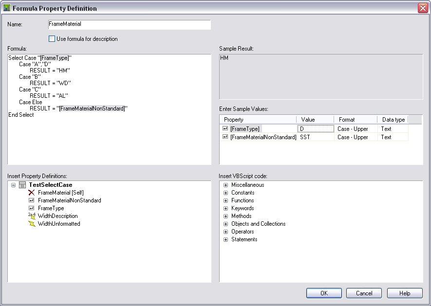
FrameType "D"
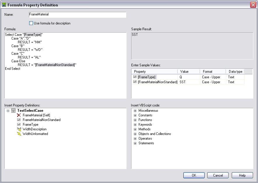
FrameType "Q"
Subscribe to:
Posts (Atom)