December 24, 2007

AB114-4 Class Materials and Webcast

UPDATE: Autodesk has decided to drop hosting of "old" AU content, but AUGI has stepped in and is hosting the content from Autodesk University 2000 through 2007 and is making it available to all members, including those at the "free" level (current as of 11/01/2013). My class can be found here: Forum > English Forums > Conferences > Autodesk > Autodesk University 2007 > Building Design > AB114-4: Get Fully Equipped in AutoCAD® Architecture. There is a ZIP file you can download which includes the class handout and the sample files that were previously available at the Autodesk site. The screencast is not available.

If you were not lucky enough to attend Autodesk University 2007, like those below who attended my Equipment Schedule class, you can still benefit from the session handouts and, for many classes, additional materials and screencasts of the presentations that were made.
If you are not already a registered user of the Autodesk University website, your first step will be to register and set up a login and password, on the Join page. If you have already registered or attended AU 2006 or 2007, you can login on the Login page. Login and/or Join links occur in the upper right corner of the various Autodesk University website pages, also.
Once you have logged in, click on the Sessions link,and then use the Search Sessions area to help you find the session and session materials you want. For example, to find my session, set the year to 2007 and the Speaker to "David Koch".Click on the Search button and a list of the sessions that meets the criteria you set will be displayed. In this case, that would be just one session, AB114-4.Click on the Session Name / Track link to go to a page that has details about the session, and links to the available handout, sample files and screencast. The screencast consists of the audio part of the presentation along with what was projected on the screen during the session. This year, you can also choose to download a screencast, in addition to streaming it.

December 11, 2007

AEC Survey

Want to give Autodesk a piece of your mind? You can do so, in a controlled manner, by taking the survey you will find in the link posted in this thread in the AutoCAD® Architecture Discussion Group.

November 23, 2007

Multi-View Block Tools in AutoCAD® Architecture 2008

In preparing class materials for my class at AU, I discovered an issue with Multi-View Block tools in AutoCAD® Architecture 2008. The behavior varies and seems partially dependent upon the settings for Drawing Scale and Annotation Plot Size, but what appears to be happening is that instead of respecting the X-, Y- and Z-scale factors set in the Multi-View Block tool's properties, the X-scale factor is being multiplied by the annotation scale factor (a product of the Drawing Scale factor and the Annotation Plot Size) and that scale factor is used for all three scale factors (X, Y and Z). Occasionally, the first use of a Multi-View Block tool results in the annotation scale factor being applied twice. This effect holds true both for Multi-View Blocks whose view blocks are drawn at full size, and were to be inserted with scale factors of 1, as well as for unit-block-based Multi-View Blocks, which were intended to be inserted with X-, Y- and Z-scale factors representing the overall size of that particular use of the unit block, and which were generally not uniform. None of the view blocks associated with these Multi-View Blocks had any attribute definitions or any sort of text included. While this behavior is annoying enough for the Multi-View Blocks that were to be inserted with scale factors of 1, it becomes all but a deal breaker for the unit-block-based Multi-View Blocks, as having the scale factors preset in the tool properties is critical to getting those Multi-View Blocks inserted correctly and consistently.

Even more bizarrely, the scale factors reported in the Multi-View Block tool's properties actually change with no user intervention! You will have to take my word for it, but the Draeger Anesthesia Machine Multi-View Block was set up in the source file with the correct X-, Y- and Z-scale factors and a Multi-View Block Tool created from that source file; the scale factors in the tool are correct with the source file open and the active file. Starting a new file results in the scale factors changing, as shown below.
Placing an instance using this tool results in those same scale factors being applied.


In some tests, I found that eventually the correct sizes would be set, but other times the incorrect sizing persisted for as long as I could be bothered to keep trying. I also found that once a file started behaving correctly, there was no guarantee that after saving and reopening the file (especially if AutoCAD Architecture was shut down and restarted in between), that the correct behavior would continue.

I eventually found the following two options would get AutoCAD Architecture to respect the scale factors set in a Multi-View Block tool's properties. You may need to repeat one of these options after saving, closing and later reopening the file.

1. Manually running the MVBLOCKADD command (I typed in the command at the Command: prompt) and inserting a Multi-View Block resulted in subsequent uses of Multi-View Block tools scaling the inserted blocks correctly.

2. Inserting a Multi-View Block through a Multi-View Block type of AEC Content, either directly from the AEC Content tab of DesignCenter or through a Tool palette tool that references AEC Content (drag the content from the AEC Content tab in DesignCenter onto an editable tool palette) also results in subsequent uses of Multi-View Block tools respecting the scale factors set in the tool's properties.

You could just make AEC Content of all of your Multi-View Block content, but that requires maintaining a separate file for each Multi-View Block Definition, rather than having a single source file, and you can not set Layer Key Overrides on AEC Content tools, whereas you can do so on Multi-View Block tools. Given the hassle of manually typing the MVBLOCKADD command and inserting a Multi-View Block (especially if there are no Multi-View Block Definitions in the file, which would require placing one instance from the tool at the incorrect scale, inserting one instance manually and then probably erasing them both, as the first is incorrectly scaled and the latter may be on the wrong layer and may also not be correctly scaled), I have decided that it would be easier to create a non-plotting Multi-View Block Definition, make an AEC Content file for it and finally making a tool from the AEC Content file. This tool can be placed on the same Tool palette as the other Multi-View Block tools, used once to get the scales on the Multi-View Blocks to be respected, and then that instance erased or left in place, as it will not plot. Dragging and dropping that tool is much faster than manually running the MVBLOCKADD command.

The properties of the tool that invokes the AEC Content file for the non-plotting Multi-View Block are shown below. Note that there is no additional control over the insertion, other than that set in the AEC Content file, which does not allow for Layer Key Overrides.
Using this tool results in inserting the non-plotting Multi-View Block with the scale factors (all 1) set in the AEC Content file.


Once this block has been placed, the properties of the Draeger Anesthesia Machine Multi-View Block tool magically return to the values originally set on the instance in the source file used to create the tool...
...and using the tool now results in a correctly scaled instance of the Multi-View Block being placed.


I did not see this problem in the 2007 or earlier releases, and I hope the problem can be eliminated from the the 2009 release.

October 11, 2007

Get Them While They Are Hot

Two new hot fixes have been posted for AutoCAD Architecture 2008, to be applied after Service Pack 1 is installed:

Raster Images in File Causing Fatal Errors

Linetypes Unexpectedly Displaying as Continuous

October 07, 2007

Startup Dialog in AutoCAD® Architecture 2008

If there are others out there who, like me, prefer to start up AutoCAD® Architecture 2008 the same way they have started earlier versions of Autodesk® Architectural Desktop, with the Startup dialog, you may be surprised to find that the Systems tab of the Options dialog no longer offers the option to activate the Startup dialog. This setting was formerly available in the General Options area in the upper right corner of the tab, as seen below in a screen capture from the 2007 release.
As seen below, the 2008 version no longer offers this as a setting.
Thanks to a tip posted by ScottE in answer to his own question in a thread in the AutoCAD Architecture 2008 Discussion Group, I can report that while the ability to set turn on the Startup dialog is no longer in the Options dialog, you can still turn it on, using the STARTUP System Variable. Set STARTUP to 1 to activate the Startup dialog.
If your only use of this is to select a starting template, then you may not need to activate it. I find it useful for those occasions where I want to start a file from scratch, such as when I am creating the initial working file from which I will create AEC Content, and I want to keep the overhead in the AEC Content file as low as possible.

September 19, 2007

AU Early Bird Deadline Coming Up Fast!

The early-bird registration deadline is October 7, 2007. That is little more than two weeks from now. If you have been considering going to AU this year but have not yet registered, get your ducks in a row and do so before October 7, or it will cost you an extra $500 US.


This message brought to you as a public service by Get Fully Equipped in AutoCAD Architecture (AB114-4), Tuesday, November 27, 3:00 - 4:30 pm. I hope to see you there.

AutoCAD® Architecture 2008 Service Pack

Service Pack 1 for AutoCAD® Architecture 2008 is now ready for download; you can find it here. Do not forget to download and read the README!

September 09, 2007

OSNAP Toggle Macro

There was a request for a macro to toggle the running object snap (OSNAP) settings between "off" and a specific combination of OSNAPs, in a thread in the AutoCAD Architecture 2008 Discussion Group. I posted some AutoLISP code in reply, and thought I would archive the code here and explain how it works.

The OSMODE system variable keeps track of which OSNAP settings are active, and whether running object snap is turned on or off. The value stored in the OSMODE system variable is "bit coded". A bit coded system variable allows multiple, related items that can be either "on" or "off" to be tracked "separately" in one number. If you expressed that number in Base 2, each digit (or "bit") will either be zero (not set, or off) or a one (set, or on). Each OSNAP setting is assigned to a particular digit, and if that bit is "set" (1), that OSNAP is on. If all of the bits are set to zero, then the NONe OSNAP is "set". The decimal value held in the OSMODE system variable is the sum of the associated decimal values of each of the set bits. As noted in the Help, the following indicates the bit with which each OSNAP is associated.
OSNAP
  
Decimal Value
ENDpoint 1
MIDpoint 2
CENter 4
NODe 8
QUAdrant 16
INTersection 32
INSertion 64
PERpendicular 128
TANgent 256
NEArest 512
Clears all object snaps 1024
APParent Intersection 2048
EXTension 4096
PARallel 8192

There is also an additional bit setting for the 16384 bit. If this bit is set, then running object snaps are turned off, but the individual snap settings are retained and can be reactivated by clearing the 16384 bit. So there are two ways in which runnning object snaps can be off: either none are set (OSMODE = 0) or the 16384 bit is set (OSMODE > 16383). These are the tests that my macro code uses to test whether running object snaps are inactive. If inactive, OSMODE is set to the desired combination of OSNAPs - in this example, endpoint (1), intersection (32), perpendicular (128) and nearest (512); otherwise, 16384 is added to the current value to set the 16384 bit and turn off running object snaps. Rather than adding the bit codes and entering that specific number, I used the AutoLISP "+" function to do the adding for me. This may slow down execution a bit, but it makes seeing what OSNAPs are being set by the code much clearer and makes adding or removing a particular OSNAP easier, too.

The macro code could be assigned to a function key or a keyboard accelerator, as the person making the request in the Discussion Group wanted, or it could be assigned to a toolbar button or to a command tool on a Tool palette. Similar code could be put into an AutoLISP function which, when loaded, could be run by any of the above methods or at the Command: prompt by typing in the function name.

MACRO CODE:
(if 
(or
(= (getvar "OSMODE") 0)
(> (getvar "OSMODE") 16383)
)
(setvar "OSMODE" (+ 1 32 128 512))
(setvar "OSMODE" (+ (getvar "OSMODE") 16384))
)


MACRO CODE in an AutoLISP Function:
(defun C:OSM ( / aosmo)
(setq aosmo (getvar "OSMODE"))
(if
(or
(= aosmo 0)
(> aosmo 16383)
)
(setvar "OSMODE" (+ 1 32 128 512))
(setvar "OSMODE" (+ aosmo 16384))
)
(prin1)
)

August 22, 2007

AU 2007: Get Fully Equipped in AutoCAD Architecture

Just a reminder for those of you fortunate enough to be registering for AU, I will be teaching a course called Get Fully Equipped in AutoCAD Architecture (AB114-4), which is scheduled for Tuesday, November 27, from 3:00 pm to 4:30 pm in Murano 3203. It is the only AutoCAD Architecture class currently scheduled in that time slot, and I hope to see you there.

Come see a method of creating and scheduling equipment that I have used for several health care projects and which could easily be used on laboratory projects or adapted to any other project type where you need to show equipment or furniture in plan, with identifying tags and then create a schedule to list those items and related data. Equipment not your thing? Then come to see how to analyze a scheduling task and apply the schedule features in AutoCAD Architecture to meet the needs.

Be sure to check out Matt Dillon's Schedule Anything in AutoCAD Architecture or AutoCAD MEP, on Friday, November 30, from 8:00 am - 11:30 am and leave AU 2007 a scheduling pro!

August 06, 2007

Details: Welding Symbols Layer Key

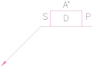
Those of you using ADT 2005 or later may have discovered the nifty welding symbols tool on the Basic tool palette in the Detailing tool palette group.Running this tool opens the Welding Symbols dialog box, which allows you to select from a number of different welding symbol options, and, for those with attributed blocks, provide values for that block's attributes.
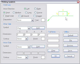
Selecting OK results in the insertion of one or more blocks that form the symbol, and allows you to create one or more leaders to point to the place(s) where the weld symbol applies.
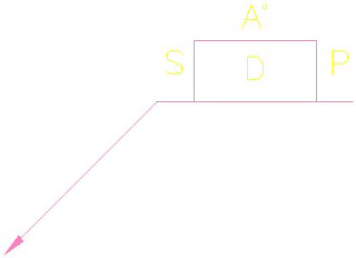
The source file for the "WPLG" plug weld block shown above is WPLG.dwg, which, like the other welding symbol blocks, can be found in the C:\Program Files\AutoCAD Architecture 2008\Welding folder if the default file locations were used on installation. The polyline that forms the linework for this block is drawn on Layer 0, with ByLayer properties, so it will inherit the layer, color, linetype and lineweight of the layer on which the block is placed. The attributes are defined on a layer called WELDTEXT, with ByLayer properties. The way Details blocks work is if the layer name on which an object is drawn matches a Layer Key name in the current Layer Key Style, then that object, when inserted into the drawing, will be put on the layer assigned to that Layer Key.

The overall welding symbol is assigned to the ANNOBJ Layer Key, so the block(s) and leaders are placed on the A-Anno-Note layer for the out-of-the-box AIA (256 Color) Layer Key Style, with no overrides set. Unfortunately, the AIA (256 Color) Layer Key Style that has shipped with the program since ADT 2005 does not contain a Layer Key called WELDTEXT. Nor do any of the other out-of-the-box Layer Key Styles that I have examined.Because of this, ADT/ACD-A simply keeps the attributes on the WELDTEXT layer, as defined in the source file. (As always, click on any "reduced size" image file to see the image full size.)
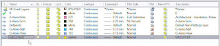
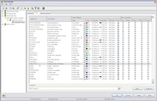
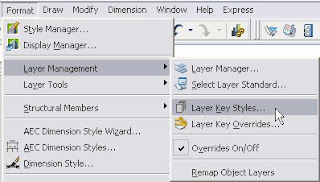
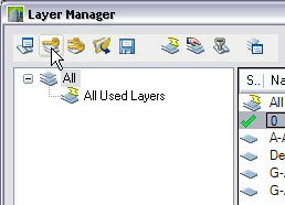
Fortunately, adding a Layer Key is quite easy, so if you want to get the attributes of your welding symbols on a layer other than WELDTEXT, add a WELDTEXT Layer Key and specify the layer name and properties of the layer on which you want the attributes to be placed. You can edit a Layer Key Style through the Style Manager (Format > Style Manager..., then look in the Multi-Purpose Object folder -OR- Format > Layer Management > Layer Key Styles... from the pulldown menus) or by opening the Layer Manager and selecting the Layer Key Styles button (second from left) on the toolbar at the top of the dialog.
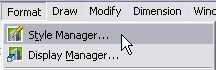
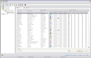
Once you have the Style Manager open and have found and expanded the Layer Key Styles category in the Multi-Purpose Objects folder, select the name of the Layer Key Style you use in the left pane, and then select the Keys tab in the right pane. Left click on the New button at the lower right corner.
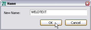
In the Name dialog, type WELDTEXT in the edit box and select OK to create a new Layer Key of that name.
Enter a description for the Layer Key, and add a layer name (use the ellipsis button to build a layer name from predefined components in your Layer Standard) and set the layer parameters. I chose color 182, a dark purple, for contrast with the default yellow color. You may wish to choose a different color.One curious "feature" when adding a new Layer Key that I have never understood is that the Allow Overrides toggles for the new Layer Key are not active. You will need to "Apply" your changes, then reselect the name of your Layer Key Style in the left pane. Now the Allow Overrides toggles are active, and you can, if you wish, check them to allow Layer Key Overrides to be applied to the various components of the layer name.

Once you have tested the new Layer Key, you will want to copy the revised Layer Key Style to your auto-import file. You can find the name and location of this file on the Layering tab of the Drawing Set dialog. If you have the "always import" toggle on that tab checked, the updated Layer Key Style will be imported when opening existing drawings and using any feature that involves a Layer Key. If you do not have the "always import" toggle checked, you will need to update the Layer Key Style in any existing drawings manually. I would recommend having the "always import" toggle checked; if you do not, at the very least you should make certain that your template files do not have a Layer Key Style defined within them, so that new files will always inherit the latest version of the Layer Key Style from the auto-import file.

Note also that in any existing files in which you have already placed a particular attributed welding symbol block, the WELDTEXT layer is already built into the block definition, and you would need to redefine the block manually, then use ATTSYNC to update the attributes of the previously existing instances of that block. But for new drawings, or for blocks not already defined, that have the new Layer Key Style with the WELDTEXT Layer Key, the attributes will now be placed on the layer assigned to the WELDTEXT Layer Key.