Showing posts with label Railing. Show all posts

October 28, 2018

ACA: Custom Profile for Railing Plan Display Representations

As noted in a previous post about Custom Blocks for Railings, those blocks can only be attached to the Model Display Representation. While the Plan, Plan High Detail, Plan Low Detail and Plan Screened Display Representations do not allow for Custom Blocks, they do allow for Custom Profiles, which may work for showing a base plate at each post, depending upon how fussy you are about the graphics. One might first ask the question, "Do I really need to see base plates in a plan view of a Railing?" At typical plan scales (1:100, 1/8" = 1'-0", 1:50, 1/4" = 1'-0"), one could make a convincing argument that the added graphic will, at best, be a slightly wider blob, with the lineweights causing the plotted linework to merge with the railing and post graphics. For the purposes of this example, lets say that for the High Detail Display Configuration/Plan High Detail Display Representation Set (Top view direction)/Plan High Detail Display Representation for Railings, we do want to show the base plates. This can be done by adding a Custom Profile to the post components.

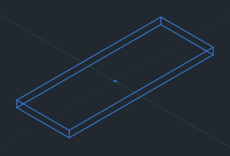
Before we can add a Custom Profile, we have to define the Profile. To do so, I drew a closed Polyline to show the 5.5" x 2" top view rectangle of the base plate that was created in the previous article, as shown in the image below, taken from a SW Isometric view. The Color 140 diagonal line is a Line on layer G-Anno-Nplt and will not be part of the profile, but is there to make it easy to specify the insertion point of the Profile, by snapping to the midpoint of the Line.

Create a Profile from this Polyline by doing the following:
  • Select the Polyline, and right click. Choose Convert To > Profile Definition from the context menu.
  • At the Insertion point or [Add ring Centroid] command line prompt, select the midpoint of the diagonal Line, using the Midpoint object snap.
  • In the New Profile Definition dialog, enter a name for the Profile, in the New Name edit box. I chose to call the Profile in this example RailingPostBasePlate. Select the OK button.

The Profile for the base plate is now available. If you want, you can open the Style Manager and take a look at it, under Multi-Purpose Objects > Profiles. If you do take a look, close the Style Manager without making any changes.

The newly created Profile can now be added as a Custom Profile to the Posts in the Railing.
  • Edit the Railing Style.
  • On the Display Properties tab, select the Plan High Detail Display Representation. Depending upon what view direction and Display Configuration are current, this may or may not be the Display Representation in bold type.
  • Left click on the toggle in the Style Override column on the Plan High Detail Display Representation line to create a style-level override and open the Display Properties dialog for the overridden Plan High Detail Display Representation.
  • In the Display Properties dialog, select the Other tab.
  • Select the Add button. This will open the Custom Profile dialog.
  • In the Custom Block dialog, select the Select Profile button, and then choose the Profile Definition for the base plate in the Select a Profile dialog.
  • Select OK to ratify the choice of Profile and return to the Custom Profile dialog.
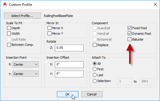
  • Since we want this added to the Posts, in the Component area at the upper right, clear the check mark from the Baluster toggle and add one to both the Fixed Post and Dynamic Post toggles. We only want to add this block to the existing posts, not replace the posts, so leave the Replace toggle unchecked.
  • Verify that none of the toggles in the Scale To Fit or Mirror In areas are checked.
  • Verify that the Insertion Point is set to Center for X and Y. This matches the insertion point of the RailingPostBasePlate Profile that was created.
  • Verify that the Insertion Offset values are all set to 0.
  • Choose an appropriate radio button in the Attach To area. Since I wanted all posts to have the base plate, I chose All in this example.
  • Select OK to ratify the Custom Profile settings, dismiss the Custom Profile dialog and return to the Display Settings dialog.
  • Select the Layer/Color/Linetype tab.
  • Notice that, unlike with Custom Blocks, there is not a new Display Component listed for the Custom Profile. Based on some experimentation with the Color property, it does not appear that the Custom Profile is associated with any of the Display Components shown, either, but behaves as if ByBlock were selected for each property.
  • Select the OK button twice, to accept all the edits made, dismiss the Display Properties and Railing Styles dialogs (or, if you edited the Railing Style with the Style Manager, to dismiss the Display Properties dialog and the Style Manager) and return to the drawing.
In a Top view with a Display Configuration with the Plan High Detail Display Representation for Railings active, the added Custom Profile will be seen at the posts. So far as I know, it is not possible to have any rails that cross over the Custom Profiles hide the Custom Profile linework that passes "under" the rail. Most likely because the rail is just two lines in this Display Representation, not a solid object, and ACA has no way of knowing that the Custom Profile represents a base plate down at the bottom of the post.

Given the lack of display control and the resulting graphics, I doubt that I would use a Custom Profile to represent a railing base plate; certainly not one of this size relative to the size of the railing. I would probably only show this in a detail, with independent linework, rather than as part of the model. One other interesting effect to keep in mind should you decide to go this route, if you add a Custom Profile to all of the posts in a Railing that is anchored to a Stair object, the Custom Profile will display for each post, even those that are not drawn in the view because they are above the cut plane of the Stair. Checking the Replace toggle in the properties of the Custom Profile, so that the Profile replaces the graphics of the posts does not affect the display behavior here. The posts will not be drawn, but all of the base plates will show at the Stair, and they will display with ByBlock display properties, not the display properties assigned to any of the post components.

October 24, 2018

ACA: Custom Block for Railing Model Display Representation

The Model Display Representation of Railings in AutoCAD® Architecture allow for the addition of custom blocks to create additional display components for the Railing. For example, you can add base plates to the Railing Posts. For this example, I started with the out-of-the-box Guardrail - Pipe Railing Style and renamed it to Guardrail - Pipe with Base Plate.

The first step is to create an AutoCAD Block Definition to represent the base plate. I decided that the base plate should be 5.5" long, 2" wide and 1/4" high, and I wanted to be able to use the same Material Definition that is used for the Railing, so I chose to use a Mass Element for the base plate, and created a Mass Element Style, called Stainless Steel, that had the same Material Definition assigned. In the example file, which can be found in this AutoCAD Architecture forum post, I used the out-of-the-box Metals.Metal Handrails and Railings.Stainless Steel.Satin Material Definition. Using the Stainless Steel Mass Element Style, I created a "Box" shaped Mass Element of the desired dimensions.

I then made a Block Definition with the Mass Element as the only included object, with the insertion point at the centroid of the bottom face of the Mass Element.


With the Block Definition created, the next step is to add it to the Railing. This is done in the Railing's Display Properties, in the Model Display Representation. Because I want this block to be added to all instances of this Railing Style, but do not want it to be added to all Railings, this was done as a Style-level Display Override.
  • Edit the Railing Style.
  • On the Display Properties tab, select the Model Display Representation. Depending upon what view direction and Display Configuration are current, this may or may not be the Display Representation in bold type.
  • Left click on the toggle in the Style Override column on the Model Display Representation line to create a style-level override and open the Display Properties dialog for the overridden Model Display Representation.
  • In the Display Properties dialog, select the Other tab.
  • Select the Add button. This will open the Custom Block dialog.
  • In the Custom Block dialog, select the Select Block button, and then choose the Block Definition that contains the base plate in the Select a Block dialog.
  • Select OK to ratify the choice of block and return to the Custom Block dialog.
  • Since we want this added to the Posts, in the Component area at the upper right, clear the check mark from the Baluster toggle and add one to both the Fixed Post and Dynamic Post toggles. We only want to add this block to the existing posts, not replace the posts, so leave the Replace toggle unchecked.
  • Verify that none of the toggles in the Scale To Fit, Mirror In or Rotate areas are checked.
  • Verify that the Insertion Point is set to Center for X and Y and Bottom for Z. This matches the insertion point of the RailingPostBasePlate block that was created.
  • Verify that the Insertion Offset values are all set to 0.
  • Choose an appropriate radio button in the Attach To area. Since I wanted all posts to have the base plate, I chose All in this example.
  • Select OK to ratify the Custom Block settings, dismiss the Custom Block dialog and return to the Display Settings dialog.
  • Select the Layer/Color/Linetype tab.
  • Notice that there is a new Display Component listed, with the same name as the name of the Block Definition selected for the Custom Block. You can make any desired settings here, but since a Mass Element is the only element in the Custom Block, it will follow its own display settings for the Model Display Representation. The out-of-the-box drawing default settings display Mass Elements "By Material" for the Model Display Representation, just like all of the other Railing components. Since the same Material Defintion is assigned to the Railing components and the Mass Element in the Custom Block, they should all display alike. (If you really wanted to control the display properties of the Custom Block on the Layer/Color/Linetype tab of the Railing Display Properties, you could set a Style-level display override on the Mass Element Style for the Model Display Representation, clear the ByMaterial toggle and set all of the properties in the Mass Element Style Override to ByBlock. But that is not the goal in this example, and beyond the scope of this article.)
  • Select the OK button twice, to accept all the edits made, dismiss the Display Properties and Railing Styles dialogs (or, if you edited the Railing Style with the Style Manager, to dismiss the Display Properties dialog and the Style Manager) and return to the drawing.
If you do not already have an instance of the Railing Style in your drawing, add one, and then change to one of the isometric view directions, if you are not in one already. You should see the Custom Block at the bottom of each post.
The baseplate will show whenever the Model Display Representation for Railings is active, which is just about any Display Configuration/View Direction combination where Railings are turned on, except for the Top view direction, where one of the "plan" Display Representations will be used. The Plan Display Representations do not allow for attaching Custom Blocks, but they do allow for adding Custom Profile Displays. An article on how to do that can be found here.

April 08, 2016

ACA 2017: CReate type Command Option

Another new feature that some may find of use is the addition of a new command line option, CReate type when adding Walls, Curtain Walls, Railings, Slabs, Roof Slabs and Roofs.

Selecting the CReate type option results in a new command line prompt. The default action is to create a Rectangle shape (by picking the opposite corners of the rectangle). Other shape options are Circle, POlygon and PLine.
Command prompts for those options follow those of the AutoCAD object commands of the same name. While you may not have many occasions for wanting to draw Walls along the lines of a regular polygon, do check out the PLine option, particularly for the object types that do not offer Arc as a command line option (Railings, Slabs, Roof Slabs and Roofs) in the "regular" Add command. For Walls and Curtain Walls, the PLine option makes it much easier to create arc segments that are tangent to the previous segment. And an added bonus when creating Slabs and Roof Slabs, you do not have to explicitly close your shape, as you do when drawing segments under the "regular" Add command. Finally, when using the PLine option when creating a Roof object, you can use object snap tracking to align the next vertex with previous vertices, which you cannot do in the "regular" Add command. This makes it easier (possible) to align your last vertex with the starting vertex on initial placement, rather than having to edit it afterwards.