In response to a thread concerning Door/Window Assemblies in the Autodesk Architectural Desktop 2006 Discussion Group, I posted a sample style to the Autodesk Architectural Desktop Content Discussion Group. The 2006 Discussion Group thread also contains a link to a sample style by Paul Humphrey and a sample style attached by Jeff Hanson.
The original request in the thread was for a way to have a fixed, 3'-0" wide by 7'-0" high door in the middle of a storefront frame, flanked by equal panels at a maximum width of 4'-6". In my style, I chose to set both the default frame and default mullion to the same size, 2" wide by 4 1/2" deep. The Primary Grid is assigned a vertical manual division with gridlines set at plus and minus 1'-7" from the grid middle. This sets the width of the center cell for the door. The all of the cells in the primary grid are assigned a nested grid.
The nested grid for the start and end cells of the primary grid have a vertical fixed width division with the cell dimension set to 4'-6". Auto-adjust cells is turned on and set to "Grow" - all three "specific cell" options are unselected, to generate equal widths. The default infill is used for these, which I modified to be 1/4" thick and to which I assigned a glass material.
The nested grid for the remaining cell [all unassigned] is a horizontal manual division with a grid line set at 7'-1" from the grid bottom, fixing the door height at 7'-0". The bottom cell in this grid is assigned a frameless door style, so that the door itself will fill the opening; the top cell [all unassigned] gets the default infill. A frameless door style is nothing more than a door style where the frame width has been set to 0.
After placing an instance of this Door/Window Assembly, I edited the infill of the cell with the door and turned off the bottom frame for that infill, so the door gets the full 7'-0" opening height. I transferred the Design Rules to the instance, then back to the style, saving the override to the style so that the door cell will always have the bottom frame removed. You can read a more detailed explanation of how to do that, along with how to turn off the display of sills while turning on the display of the bottom frame, to get the lines out of your door opening in plan view [which I did NOT do in the initially posted sample file] by reading a previously posted article, "Removing Unsightly Bottom Frames at Doors". Here is something that I just discovered - unachored [no wall selected when placed] Door/Window Assemblies will not automatically display the frame below, even when that component is turned on, whereas those anchored to walls will. You have to use the same trick used for Curtain Walls, and set a manual cut plane that passes through the frame on the Other tab of the Plan Display Representation [or whatever Display Representation is active for a top view direction in the Display Configuration you use for plan views]. A height of 0 works if the bottom of your bottom frame that is at that elevation.
Note that if your Door/Window Assembly overall height is not at least 7'-2", the door will be less than 7'-0" tall, since the cell will be less than that. Heights over 7'-2" and up to 7'-4" are "weird" in that the mullion gets drawn and, until you hit 7'-4", is pushed into the top frame. At 7'-4", the mullion and frame are side by side; over 7'-4" and you get some transom glass.
April 29, 2005


April 27, 2005
Matt Dillon on Display Themes
Matt Dillon has posted an overview of the new Display Themes feature in Autodesk Architectural Desktop 2006. This feature allows you to change the display of ADT objects based on values stored in one or more properties attached to the object. Read his article by clicking here.
April 19, 2005
Scale-Dependent Tags in ADT
There are several scale-dependent tags in the out-of-the-box content provided with ADT. Scale-dependent tags allow you to place a single tag and have the size of the tag change for plotting at different scales. The most commonly used one would be for room names and numbers; the imperial version supports plotting at 1/16” = 1’-0”, 1/8” = 1’-0” and 1/4” = 1’-0”.
The first thing to note is that the out-of-the-box tags that are scale-dependent also happen to be project based; to be able to use these as is, you would need to be using Project Navigator and the Drawing Management system. You do not need to be using Project Navigator to use scale dependent tags, you simply need to have your tags reference the non-project dependent properties that you are likely already using for a non-scale-dependent tag.
Please note that the following is based on the room tag, imperial content, for ADT2004. I believe that the ADT2005 and ADT2006 content is not much different [if at all]; the metric content is likely similar, with different scale factors. Other scale-dependent tags would, of course, have different Multi-View Block [MVB] and view block names.
The scale-dependent tags rely on the use of the display system to selectively display one of three view blocks associated with the MVB tag. The tags do not change when you change the drawing scale - you need to change the current Display Configuration to one that uses the desired MVB Display Representation [DR]. The following DR's have the noted view block assigned:
Plan DR: Aec4_Room_Tag_MedDtl_P for the Top view direction
Plan High Detail DR: Aec4_Room_Tag_HiDtl_P for the Top view direction
Plan Low Detail DR: Aec4_Room_Tag_LoDtl_P for the Top view direction
The three view blocks are identical, except for size. The entire MVB is designed to be inserted at a scale factor of 1; the blocks are scaled to be plotted at 1/8" = 1'-0" [Plan DR], 1/4" = 1'-0" [Plan High Detail DR] and 1/16" = 1-0" [Plan Low Detail DR]. This forces you to make do with these three scales [which, in my experience, are the three most common scales likely to be used by a floor plan] but avoids the problem of figuring out what drawing scale to use when inserting the tag. Note also that because the view blocks are prescaled for a particular plot scale, they do not use annotation scaling. This means that resetting the annotation plot size on the Scale tab of the Drawing Setup dialog has no effect on these tags. If you have a project that needs a different text size, you will need to create a separate scale-dependent tag with appropriately defined view blocks.
If you are not using Project Navigator, then your room numbers are not being created by a concatenation of the project-based level and an increment. You can make a copy of one of the project-based, scale-dependent tags and modify it to reference whatever property you are using for your room numbers instead of the project-based room number. This is done by changing the attribute tag to reference the desired property. See more on this here. I would suggest renaming both the MVB and the individual view blocks when making the changes, then running the revised content file back through the AEC Content Wizard and plugging in the new names on the first "page" [add the MVB and view block names to the Content File list box and change the command string, substituting your MVB name for the old MVB name]. That will avoid any unpleasant conflicts should you try to use the new content file in a file that already has the old MVB and/or view blocks defined. Drag your newly created tag from the Custom tab of DesignCenter onto an editable tool palette and you will have a tool palette access to your new tag.
The first thing to note is that the out-of-the-box tags that are scale-dependent also happen to be project based; to be able to use these as is, you would need to be using Project Navigator and the Drawing Management system. You do not need to be using Project Navigator to use scale dependent tags, you simply need to have your tags reference the non-project dependent properties that you are likely already using for a non-scale-dependent tag.
Please note that the following is based on the room tag, imperial content, for ADT2004. I believe that the ADT2005 and ADT2006 content is not much different [if at all]; the metric content is likely similar, with different scale factors. Other scale-dependent tags would, of course, have different Multi-View Block [MVB] and view block names.
The scale-dependent tags rely on the use of the display system to selectively display one of three view blocks associated with the MVB tag. The tags do not change when you change the drawing scale - you need to change the current Display Configuration to one that uses the desired MVB Display Representation [DR]. The following DR's have the noted view block assigned:
Plan DR: Aec4_Room_Tag_MedDtl_P for the Top view direction
Plan High Detail DR: Aec4_Room_Tag_HiDtl_P for the Top view direction
Plan Low Detail DR: Aec4_Room_Tag_LoDtl_P for the Top view direction
The three view blocks are identical, except for size. The entire MVB is designed to be inserted at a scale factor of 1; the blocks are scaled to be plotted at 1/8" = 1'-0" [Plan DR], 1/4" = 1'-0" [Plan High Detail DR] and 1/16" = 1-0" [Plan Low Detail DR]. This forces you to make do with these three scales [which, in my experience, are the three most common scales likely to be used by a floor plan] but avoids the problem of figuring out what drawing scale to use when inserting the tag. Note also that because the view blocks are prescaled for a particular plot scale, they do not use annotation scaling. This means that resetting the annotation plot size on the Scale tab of the Drawing Setup dialog has no effect on these tags. If you have a project that needs a different text size, you will need to create a separate scale-dependent tag with appropriately defined view blocks.
If you are not using Project Navigator, then your room numbers are not being created by a concatenation of the project-based level and an increment. You can make a copy of one of the project-based, scale-dependent tags and modify it to reference whatever property you are using for your room numbers instead of the project-based room number. This is done by changing the attribute tag to reference the desired property. See more on this here. I would suggest renaming both the MVB and the individual view blocks when making the changes, then running the revised content file back through the AEC Content Wizard and plugging in the new names on the first "page" [add the MVB and view block names to the Content File list box and change the command string, substituting your MVB name for the old MVB name]. That will avoid any unpleasant conflicts should you try to use the new content file in a file that already has the old MVB and/or view blocks defined. Drag your newly created tag from the Custom tab of DesignCenter onto an editable tool palette and you will have a tool palette access to your new tag.
April 14, 2005
Selection Previewing Update
I suppose I am giving away my age in noting that the first place I look when trying to control a new feature is for a system variable or two. Thanks to a heads up from Desktops Product Planning Manager Chris Yanchar, I can note that there is an easier way to control the new Selection Preview feature - on the Selection tab of the Options dialog. The following images illustrate the available options and where to set them, with no need to remember any obscure system variable names or bitcodes. ;-)

Selection tab of Options dialog

Visual Effect Settings

Advanced Preview Options
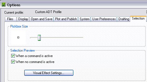
Selection tab of Options dialog

Visual Effect Settings
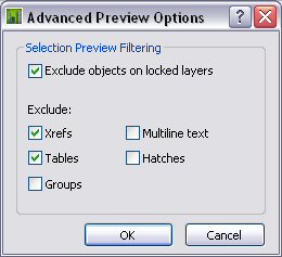
Advanced Preview Options

April 13, 2005
Selection Previewing in ADT/AutoCAD 2006
AutoCAD 2006 and, by extension, ADT 2006, include a new feature that has drawing objects highlight as the cursor rolls over them. This gives a preview of the object that would be selected if you clicked at any given moment. Some of you may like it, some may hate it. Here is how to turn it on, turn it off and fine tune its use, to suit your tastes.
There are three system variables that control this new behavior. The SELECTIONPREVIEW system variable is the sledgehammer: use it to turn off the highlighting altogether [0], on when no command is active [1], on when a command is active [2] or always on [3]. If you leave it on for at least part of the time, the PREVIEWEFFECT system variable controls what is displayed: 0 = dashed lines, 1 = thickened lines and 2 = dashed and thickened lines. The PREVIEWFILTER system variable allows you to exclude certain items, if you leave it turned on. See the list of bitcodes below for items that can be excluded.
From the Help:
--------------------------------------------------------------------------
SELECTIONPREVIEW System Variable
Type: Bitcode
Saved in: Registry
Initial value: 3
Controls the display of selection previewing. Objects are highlighted when the pickbox cursor rolls over them. This selection previewing indicates that the object would be selected if you clicked. The setting is stored as a bitcode using the sum of the following values:
0 Off
1 On when no commands are active
2 On when a command prompts for object selection
--------------------------------------------------------------------------
PREVIEWEFFECT System Variable
Type: Integer
Saved in: Registry
Initial value: 2
Specifies the visual effect used for previewing selection of objects.
0 Dashed lines (the default display for selected objects)
1 Thickened lines
2 Dashed and thickened lines
--------------------------------------------------------------------------
PREVIEWFILTER System Variable
Type: Bitcode
Saved in: Registry
Initial value: 1
Excludes specified object types from selection previewing. The setting is stored as a bitcode using the sum of the following values:
0 Excludes nothing
1 Excludes objects on locked layers
2 Excludes objects in xrefs
4 Excludes tables
8 Excludes multiline text objects
16 Excludes hatch objects
32 Excludes objects in groups
There are three system variables that control this new behavior. The SELECTIONPREVIEW system variable is the sledgehammer: use it to turn off the highlighting altogether [0], on when no command is active [1], on when a command is active [2] or always on [3]. If you leave it on for at least part of the time, the PREVIEWEFFECT system variable controls what is displayed: 0 = dashed lines, 1 = thickened lines and 2 = dashed and thickened lines. The PREVIEWFILTER system variable allows you to exclude certain items, if you leave it turned on. See the list of bitcodes below for items that can be excluded.
From the Help:
--------------------------------------------------------------------------
SELECTIONPREVIEW System Variable
Type: Bitcode
Saved in: Registry
Initial value: 3
Controls the display of selection previewing. Objects are highlighted when the pickbox cursor rolls over them. This selection previewing indicates that the object would be selected if you clicked. The setting is stored as a bitcode using the sum of the following values:
0 Off
1 On when no commands are active
2 On when a command prompts for object selection
--------------------------------------------------------------------------
PREVIEWEFFECT System Variable
Type: Integer
Saved in: Registry
Initial value: 2
Specifies the visual effect used for previewing selection of objects.
0 Dashed lines (the default display for selected objects)
1 Thickened lines
2 Dashed and thickened lines
--------------------------------------------------------------------------
PREVIEWFILTER System Variable
Type: Bitcode
Saved in: Registry
Initial value: 1
Excludes specified object types from selection previewing. The setting is stored as a bitcode using the sum of the following values:
0 Excludes nothing
1 Excludes objects on locked layers
2 Excludes objects in xrefs
4 Excludes tables
8 Excludes multiline text objects
16 Excludes hatch objects
32 Excludes objects in groups
April 09, 2005
April 2005 AUGI Training Program: ADT Scheduling Basics Class Offered
I am teaching a class, ATP071 Architectural Desktop's Scheduling Features, as part of the April 2005 offerings of the AUGI Training Program. There is no cost to participate in this class, other than having an Internet connection so that you can access the class materials and the dedicated forum for the class. You do need to become a member of AUGI to have access to the class, but that too is free. Check it all out at the AUGI website. Once you have joined [or, for current members, signed in] - click on the Education link in the menu bar below the logo graphics, then select AUGI Training Program > Current ATP Courses to find the current class offerings.
The class starts Monday, April 11, 2005, with Segment 1. Segments 2 and 3 will be made available on subsequent Mondays [April 18 and April 25, respectively]. There will be a dedicated Forum [discussion group] for the class, where you can post any questions that you have. I or other classmates will do our best to answer your questions in a timely fashion.
Here is a synopsis of the class content:
This course covers the components involved in scheduling in Autodesk® Architectural Desktop and the relationships between them:
No previous experience with Autodesk® Architectural Desktop’s scheduling feature is required, but general familiarity with the version of Autodesk® Architectural Desktop you are using will be helpful. At the end of the course, each student should know the scheduling components, how they relate to one another and should be able to create all of the components needed for a scheduling task.
The sample files and tutorials are based on Imperial units [feet and inches], with which I am most familiar, but the concepts should be able to be easily transferred to Metric files.
I hope to see you in the class forum! Should you be reading this post after the class has concluded, the class materials will still be available for downloading for several months after the conclusion of the course.
The class starts Monday, April 11, 2005, with Segment 1. Segments 2 and 3 will be made available on subsequent Mondays [April 18 and April 25, respectively]. There will be a dedicated Forum [discussion group] for the class, where you can post any questions that you have. I or other classmates will do our best to answer your questions in a timely fashion.
Here is a synopsis of the class content:
This course covers the components involved in scheduling in Autodesk® Architectural Desktop and the relationships between them:
- Property Data Formats
- Property Sets
- Schedule Tables
- Schedule Tags
No previous experience with Autodesk® Architectural Desktop’s scheduling feature is required, but general familiarity with the version of Autodesk® Architectural Desktop you are using will be helpful. At the end of the course, each student should know the scheduling components, how they relate to one another and should be able to create all of the components needed for a scheduling task.
The sample files and tutorials are based on Imperial units [feet and inches], with which I am most familiar, but the concepts should be able to be easily transferred to Metric files.
I hope to see you in the class forum! Should you be reading this post after the class has concluded, the class materials will still be available for downloading for several months after the conclusion of the course.
April 05, 2005
Additional AUGI CAD Camp Dates Announced
Additional dates for the next AUGI CAD Camps have been announced:
May 10, 2005 - Omaha, Nebraska (registration is now open)
May 26, 2005 - Baltimore, Maryland
June 7, 2005 - St. Paul, Minnesota
May 10, 2005 - Omaha, Nebraska (registration is now open)
May 26, 2005 - Baltimore, Maryland
June 7, 2005 - St. Paul, Minnesota
April 03, 2005
Formula Property Interface Improved in ADT 2006
Anyone who has ever created a formula property in ADT that went beyond a simple concatenation will appreciate the revised Formula Property Defintion dialog in ADT 2006. No longer does debugging your your formula require multiple loops from the drawing, where you have set up some sample test objects and maybe tags or schedules, to the Style Manager. Now you can enter your formula, provide test values for the other properties it references right in the defintion dialog and do all your debugging right there.
As if that were not enough, there is also a handy section that will add various VB Script commands/command structures to your formula with placeholders for parameters you need to enter, organized by type. Never be confused over whether there is a space in ElseIf or End If ever again. Hover over an item to see a tool tip that displays what will be inserted; if you have Internet access, right click help takes you straight to the MSDN Library help page for that command. The only way they could make this any easier would be to find a way to provide right-click access directly to Scott Arvin, and since that would seriously curtail his ability to make future improvements, I do not think anyone really wants that.
The screen capture below shows a newly created Property Set Definition intended to be used for a room name. The goal is to have two separate lines for the room name in the tag, but to have the value[s] concatenated, with a single space separator, for the schedule. A simple concatenation formula could be used, but to avoid adding the space if one or both of the manual properties are an empty string, an "if-then-elseif-else" test structure is used to test for empty strings in the manual properties and to return the appropriate value. The two manual properties have already been defined, as can be seen on the Defintion tab at the top of the screen capture; the formula property was entered and tested without even having to click OK once to save the formula. The drawing file is otherwise empty - no sample spaces, tags and schedules required.
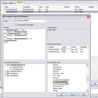
Formula Property Definition Dialog [click on image to view a larger version]
Hats off to the ADT Development team for making formula properties that much easier to create and use.
As if that were not enough, there is also a handy section that will add various VB Script commands/command structures to your formula with placeholders for parameters you need to enter, organized by type. Never be confused over whether there is a space in ElseIf or End If ever again. Hover over an item to see a tool tip that displays what will be inserted; if you have Internet access, right click help takes you straight to the MSDN Library help page for that command. The only way they could make this any easier would be to find a way to provide right-click access directly to Scott Arvin, and since that would seriously curtail his ability to make future improvements, I do not think anyone really wants that.
The screen capture below shows a newly created Property Set Definition intended to be used for a room name. The goal is to have two separate lines for the room name in the tag, but to have the value[s] concatenated, with a single space separator, for the schedule. A simple concatenation formula could be used, but to avoid adding the space if one or both of the manual properties are an empty string, an "if-then-elseif-else" test structure is used to test for empty strings in the manual properties and to return the appropriate value. The two manual properties have already been defined, as can be seen on the Defintion tab at the top of the screen capture; the formula property was entered and tested without even having to click OK once to save the formula. The drawing file is otherwise empty - no sample spaces, tags and schedules required.

Formula Property Definition Dialog [click on image to view a larger version]
Hats off to the ADT Development team for making formula properties that much easier to create and use.
March 21, 2005
ADT 2006 Tags Illustrated
There was a glitch with the Hello BloggerBot yesterday that prevented me from including all the wonderful illustrations I had prepared for my previous post. Now that it has been cleared up, here is the tutorial, complete with illustrations.
- Identify the property[ies] you wish to display in your tag, and the Property Set Definition[s] that contain that[those] property[ies], along with any other Property Sets that you would like to have your tag attach. Create any new Property Set Definitions and/or copy existing ones to the file in which you will create the tag. This can be any drawing file for learning/experimental purposes, but when you are creating “final” tags, you will want to either use the out-of-the-box Schedule Tables (Imperial).dwg or create a tag source file to hold your office’s custom tags. This file also serves as the central repository for Property Set Definitions and Schedule Table Styles, and needs to be accessible to all who will use the Tool palette tool you create for your tag.
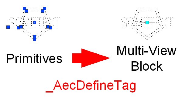
- In your source file, draw the graphics you want for the tag, using text placeholders where you want to display property data. Keep in mind that the tags will use annotation scaling, so make any placeholders you want to plot at the annotation plot size one unit high. Scale other placeholders and graphics accordingly. The string you use in your placeholder text will become the default text for the attribute definition the text will become, so choose your string with that in mind. Figure 1 below shows the primitive graphics on the left, a single piece of middle center justified text, one unit high, and two five-sided closed lwpolylines. The final tag is shown on the right. (Note: you can click on any of the pictures to see a larger, clearer version. Use the Back button on your browser to return to the post.)
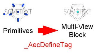
Figure 1: Primitive Graphics to Multi-View Block - Start the _AecDefineTag command; the easiest way is to choose Format > Define Schedule Tag… from the pulldown menus. Select your graphics, as directed by the command line prompt. The Define Schedule Tag dialog appears as shown in Figure 2.

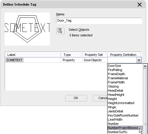
Figure 2: The Define Schedule Tag dialog - The Define Schedule Tag dialog will show a preview image of your tag in the upper left corner. To the right of that, the Name edit box allows you to give your tag a name; the same name will be used for both the view block and the Multi-View Block for your tag. There is also a Select Objects button, to allow you to change the graphics to be included in your tag. Enter a name for your tag (see Figure 3).
- Below the preview graphics and the Select Objects button is a list box that shows each placeholder text item you included in your selection set. The Label column will initially show the text string of the placeholder text. If you leave a text item “as is”, it will be static text in the view block. To get your placeholder text to be converted to a properly formatted attribute definition in the view block, click where it says “Text” in the Type column on the row of a particular placeholder, and select Property in the dropdown list, as shown in Figure 3.

Figure 3: Entering a name and changing the Type to Property Move over to the Property Set column, and choose the Property Set that includes the property you want want this placeholder to display (Figure 4). Finally, choose the property name in the Property Definition column (Figure 5). Notice that the Label has now changed to the PropertySetName:PropertyName format that will be used for the attributed defintion tag, which will be familiar to those who have created tags in prior releases (Figure 6). Repeat this process for each placeholder text you included in your tag graphics.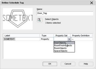
Figure 4: Selecting the Property Set
Figure 5: Setting the Property Definition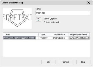
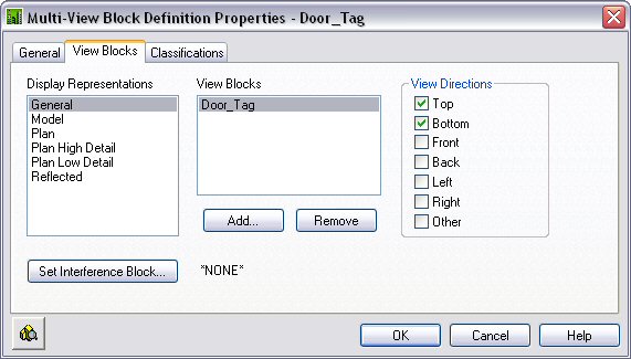
Figure 6: The Label is now formatted - When you are certain that all of the graphics are included and all of the placeholder text has been set to the correct property, select the OK in the Define Schedule Tag dialog and, following the Command line prompt, pick the point that will be the insertion point of your tag, relative to the selected graphics. The graphics are replaced with a Multi-View Block that contains a view block showing your graphics, and one or more attributes – one for each placeholder text that you converted to a property, see Figure 1 above. Save the file so that you can make a tool. Select the Multi-View Block, right click and choose Edit Multi-View Block Definition... from the context menu. Select the View Blocks tab and note that the view block created has been assigned to the top and bottom view directions for the General Display Representation for Multi-View Blocks, as indicated in Figure 7. Select the Cancel button to close the dialog without making any changes.
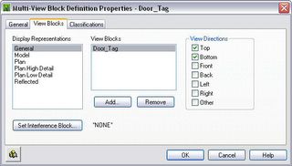
Figure 7: The View Blocks tab of the newly created Door_Tag MVB - Set an editable Tool palette current, then select the newly created Multi-View Block. Right-click and drag the Multi-View Block onto the tool palette. Edit the new tool’s properties, and set the layer key you want associated with the tool, and make any other settings. You are now ready to use your new tag. Figure 8 shows a door tagged with the example tag.

Figure 8: A tagged door




March 20, 2005
ADT 2006 Tags
If you can draft in AutoCAD, you can make an ADT tag in 2006.
The process of creating tags has been made much simpler in ADT 2006. You can avoid the AEC Content Wizard altogether for basic tags, and just use the new tag wizard. You do not even need to create a view block or a multi-view block - just place text "placeholders" where you want to display property data and draw the rest of your graphics.
Here is a quick tutorial on how to create a tag in Autodesk® Architectural Desktop 2006 using the new _AecDefineTag command:
The process of creating tags has been made much simpler in ADT 2006. You can avoid the AEC Content Wizard altogether for basic tags, and just use the new tag wizard. You do not even need to create a view block or a multi-view block - just place text "placeholders" where you want to display property data and draw the rest of your graphics.
Here is a quick tutorial on how to create a tag in Autodesk® Architectural Desktop 2006 using the new _AecDefineTag command:
- Identify the property[ies] you wish to display in your tag, and the Property Set Definition[s] that contain that[those] property[ies], along with any other Property Sets that you would like to have your tag attach. Create any new Property Set Definitions and/or copy existing ones to the file in which you will create the tag. This can be any drawing file for learning/experimental purposes, but when you are creating “final” tags, you will want to either use the out-of-the-box Schedule Tables (Imperial).dwg or create a tag source file to hold your office’s custom tags. This file also serves as the central repository for Property Set Definitions and Schedule Table Styles, and needs to be accessible to all who will use the Tool palette tool you create for your tag.
- In your source file, draw the graphics you want for the tag, using text placeholders where you want to display property data. Keep in mind that the tags will use annotation scaling, so make any placeholders you want to plot at the annotation plot size one unit high. Scale other placeholders and graphics accordingly. The string you use in your placeholder text will become the default text for the attribute definition the text will become, so choose your string with that in mind.
- Start the _AecDefineTag command; the easiest way is to choose Format > Define Schedule Tag… from the pulldown menus. Select your graphics, as directed by the command line prompt. The Define Schedule Tag dialog appears.
- The Define Schedule Tag dialog will show a preview image of your tag in the upper left corner. To the right of that, the Name edit box allows you to give your tag a name; the same name will be used for both the view block and the Multi-View Block for your tag. There is also a Select Objects button, to allow you to change the graphics to be included in your tag. Enter a name for your tag.
- Below the preview graphics and the Select Objects button is a list box that shows each placeholder text item you included in your selection set. The Label column will initially show the text string of the placeholder text. If you leave a text item “as is”, it will be static text in the view block. To get your placeholder text to be converted to a properly formatted attribute definition in the view block, click where it says “Text” in the Type column on the row of a particular placeholder, and select Property in the dropdown list. Move over to the Property Set column, and choose the Property Set that includes the property you want want this placeholder to display. Finally, choose the property name in the Property Definition column. Notice that the Label has now changed to the PropertySetName:PropertyName format that will be used for the attributed defintion tag, which will be familiar to those who have created tags in prior releases. Repeat this process for each placeholder text you included in your tag graphics.
- When you are certain that all of the graphics are included and all of the placeholder text has been set to the correct property, select the OK in the Define Schedule Tag dialog and, following the Command line prompt, pick the point that will be the insertion point of your tag, relative to the selected graphics. The graphics are replaced with a Multi-View Block that contains a view block showing your graphics, and one or more attributes – one for each placeholder text that you converted to a property. Save the file so that you can make a tool.
- Set an editable Tool palette current, then select the newly created Multi-View Block. Right-click and drag the Multi-View Block onto the tool palette. Edit the new tool’s properties, and set the layer key you want associated with the tool, and make any other settings. You are now ready to use your new tag.
For single view block tags, the new command takes care of everything. If you want to set up scale-dependent tags that do not use annotation scaling, you will have to use the Create AEC Content wizard, as in previous releases.
Additional cool features:
- ADT now recognizes tags as tags, not just as a Multi-View Block. So not only can you release the anchor of a tag, you can now re-anchor the released tag if you like, rather than erasing and re-tagging. This works for any legacy tags you have, too - you do not need to recreate any customizations you made in previous releases.
- You can right click an existing tag and choose Add Selected to use the same tag on a new object.
- With the new AecDefineTag command, you do not have to remember either the exact spelling of your Property Set Defintion name or that of the property name – nor do you have to type them correctly.
- You can specify additional property sets to be attached by the tool, without creating invisible attributes in your tag.
- You can use a variation on the tag tool to create a tool that will attach property set definitions without attaching a tag. This can be useful when you want to add a Property Set with a location grip to objects in an Element, but do not want to add a tag.
Subscribe to:
Posts (Atom)