Previous Article in the Series: AutoCAD Architecture 2009 - Part 2
Spaces
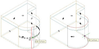
There have been several improvements to the Space object. Curved surfaces of freeform spaces are now displayed as one surface, rather than as a series of segments, as they were in previous releases. The freeform spaces shown below are from 2008, on the left, and 2009, on the right.
AutoCAD® linework, such as lines, circles and polylines, now have a "Bound spaces" property, in the Advanced category.
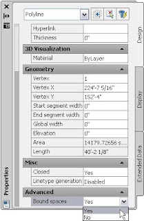 When this is set to "yes" and you are calculating Space areas from a standard, the AutoCAD linework will affect the calculation the same way as an AEC Object that is set to bound spaces. For the BOMA standard, Base and Net areas will exclude the area of bound items within the Base and Net boundaries, respectively, while Usable and Gross areas will include the area of bound items. For AutoCAD linework, it appears that the linework needs to be entirely within the Base Area boundary, while AEC Objects can straddle a Space edge and still have their area included in the Usable and Gross area. In previous versions, when AutoCAD linework formed the boundary of a Space, the Space would still be associative to it, but the area within the AutoCAD linework would not be included in any of the areas.
The associative interaction of Spaces with objects in external references is improved. In a test file, I found that reloading the external reference with changes to the walls forming the boundaries of a space would automatically update the Spaces in the host file in 2009; a manual updating of the Space geometry was necessary in 2008.
Multi-line Attribute Text in Schedule Tags
One of the cool things added in the 2008 release was the ability to set a width for an attribute in a block, and have the entered text wrap to multiple lines if it exceeded that width. Unfortunately, that ability was not supported in Multi-View Blocks, and therefore, not in Schedule Tags. The 2009 release extends that functionality to Multi-View Blocks and Schedule Tags. One common use for this will be in room tags. You will no longer need to have multiple attributes in your view block, one for each line to be supported, and either separate Manual properties for entering the lines, with a Formula property to knit them together for use in a Schedule Table, or a set of fancy Formula properties to take the value entered into a single Manual property and chop it up into smaller pieces for use in the tag. It will also make it much easier to use List Definitions for room names.
When selecting a Schedule Tag, you will now see two or three grips. The square cyan grip is the old, familiar location grip, used to move the entire tag. If the Schedule Tag is annotative, and more than one scale is assigned to the tag, then there will be a square, yellow grip for relocating the tag graphics for the current drawing scale. New to 2009, there is now a round, gray grip that is the trigger grip for editing attributes.
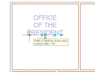
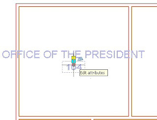 Selecting the edit attributes grip will enable a number of grips that allow you to edit the attributes, as shown in the composite image below. (Click on any image for a full-size version, then use the Back button to return here.)
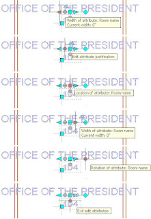 As the tooltips indicate, the two triangular cyan grips allow you to set the width of the attribute (and the tool tip lets you know the current width - 0 will display the entire text on one line). The upper circular gray grip triggers another set of grips (not shown) where you can change the justification of the attribute. The square cyan grip allows you to change the location of the attribute and the diamond cyan grip allows you to change the rotation of the attribute. The lower circular gray grip allows you to exit the attribute edit mode.
After using the left width grip (either will do) to offset the width by 3'-6", the attribute will have a total width of 7'-0"...
 ... and result in a three-line display for the featured room tag.
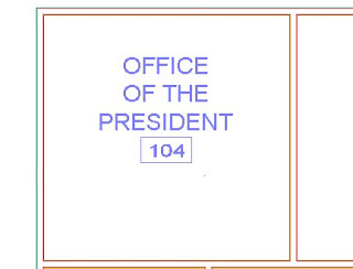 So easy, even a project manager could do it.
Additional Annotation Improvements
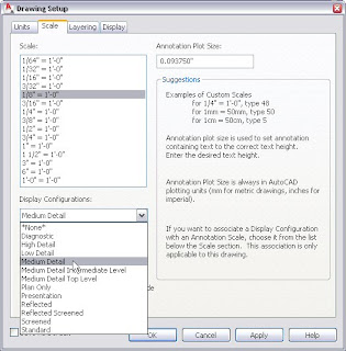
You can now associate a Display Configuration with a particular scale. Changing to that scale will also set the associated Display Configuration current. These settings are on a drawing-by-drawing basis, starting with whatever may be set in the template file, so you could have different assignments for different drawing types. For example, the imperial default setting of Medium Detail for scales from 1/8" = 1'-0" through 3/8" = 1'-0" may be appropriate for a regular plan drawing, but you will want to reset the assigned Display Configurations for a reflected ceiling plan drawing, unless you are working in a single scale. Set or change the Display Configuration assigned to a particular scale on the Scale tab of the Drawing Setup dialog.
Multi-leaders are now supported for the leader and keynoting tools.
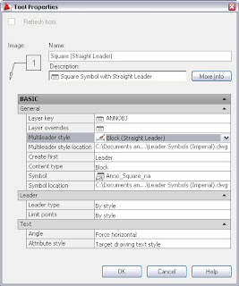
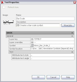
There are new tool types for inserting various types of annotation. (Out-of-the-box DesignCenter content for imperial and metric annotation is down to Chases and Elevation labels.) These include various symbols (Bar Scale, Datum Point and North Arrow, although you could customize an instance of this tool type to insert any symbol),
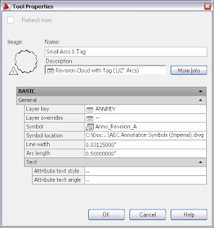
 various polyline symbol tools (fire-resistance-rating lines - line only - and match lines and revision clouds - line and symbol)
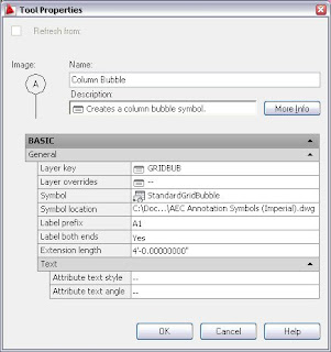
 and a Column Grid Bubble tool..
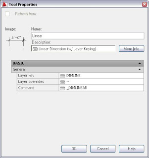
The Stock Catalog's Command Tool now also features the ability to specify a Layer Key or Layer Key Overrides! This tool type is now used to provide Dimension tools and a Shrink Wrap tool that are not dependent on AEC Content.
I hope to wrap up this overview of the new features in the 2009 release in the next installment.
Next Article in the Series: AutoCAD Architecture 2009 - Part 4
2 comments:
Great overview Dave, thanks!
-Dave Kurtz
the two triangular cyan grips are not displayed on my drawings. how can i make them appear? (it's acad2009). any advice would be much appraciated.
thanks
Post a Comment