 - Anchor properties
 - Graphic properties
Anchor properties allow you to read in property data into an object from another object to which the first object is anchored. For example, a door anchored to a wall can read property data from the wall, such as the fire-resistance rating of the wall. This was possible in ADT 2004-2006, by using some VBScript code in a formula property - see this thread in the ADT 2006 Discussion Group if you are interested - but the code was version-specific [different for 2004, 2005 and 2006], and for the 2004 and 2005 versions, would not work across external references. The new anchor property does away with all of the formula coding, and lets you choose a property from an existing property set just like you do for location properties, as shown in the Anchor Property Definition dialog below:

Graphic properties allow you to add graphics to your schedule table, by specifying either a block or an image to be displayed in the table. When creating a graphic property, you will be asked to provide a default block or image, but when you attach the property set to a style or object, you can accept the default or choose another, specific to that style/object. The layer key chosen will be applied to the blocks; if you freeze that layer, the blocks will also be frozen [and disappear].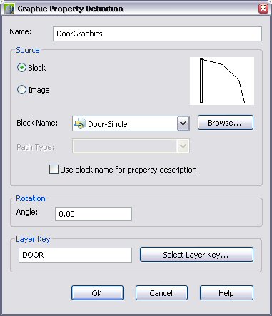
As an example, I made a copy of the out-of-the-box "DoorStyles" Property Set Definition, and added a graphic property, "DoorGraphics". I made three plan-view blocks for doors, one each for a single door, double door and double egress door. The block graphics were all drawn on layer 0, with ByBlock attributes, so they will pick up the layer attributes of the layer associated with the chosen layer key - DOOR. I set the "Door - Single" block as the default block.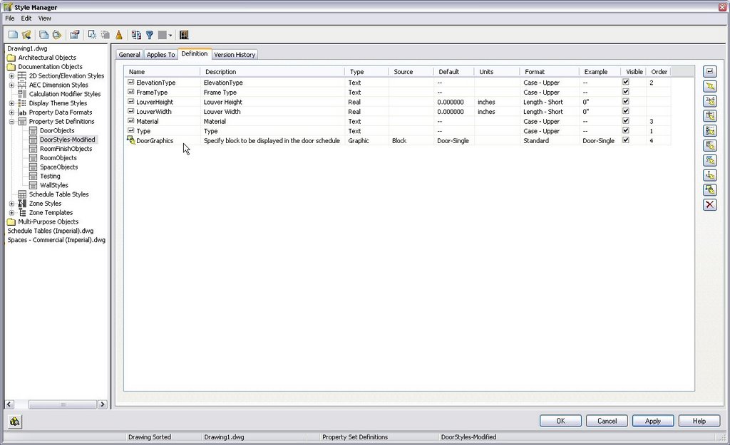
In my test file, I added a few doors of each type, then edited the door styles and added my "DoorStyles-Modified" Property Set to each, selecting the appropriate block for the double and double egress doors and accepting the default for the single doors. The Graphic Property dialog that appears is identical to the Graphic Property Definition dialog, except for the name. I then modified a copy of the out-of-the-box "Door Schedule" Schedule Table Style and added a new column referencing the DoorStyles-Modified:DoorGraphics property. The image below shows the part of the resultant door schedule. The graphics appear on the A-Door layer [which gets created, if necessary]. Note that the blocks are scaled to fit the height and width of the column, so the double egress block appears "smaller" than the other two, even though the doors swing graphics are copies, because the overall block is taller.
Also note that the blocks must exist in the drawing in order to be able to assign them to a style/object and for them to appear in the schedule. So if you create the schedule in a file that uses external references [Xrefs] in the file with the schedule, or references an external file, you will not get the images until you manually copy the blocks to the file with the schedule. If you assign a block to a graphic property in a style-based Property Set, as I did, and then use Style Manager to copy the style to a new drawing, the block name will go along with the copied style, but the block definition does not, and must be manually copied if you want to place an instance of the schedule in that file.
3 comments:
I am using these to display Air Device images, and it works great - now I am trying to figure out a way to have the image automatically adjust to the correct block name based on the model number of the device. But using a Formula Column doesn't seem to work. Here is the code I am trying:
If [Model]=TMS Then
[ImageTMS]
ElseIf [Model]=PCS Then
[ImagePCS]
End If
[ImageTMS] and [ImagePCS] are Graphic Definitions, but the Schedule Table just displays the text, not picture...
Any ideas?
-Buzz
I have not used Graphic properties all that much, and I must confess it never even occurred to me to add two to a single object and then try to get a Formula property to select the one to be displayed.
I did a quick test, and even adding RESULT = to the two lines attempting to pass through the Graphic properties did not result in a working Formula.
You can manually change the block image displayed for each instance (the one set in the Graphic property is just the initial default), so if the property were in an object-based Property Set Definition, you could change the image for each instance as desired, but I suppose your intent was to automate this. That would not appear to be possible in the current release (2009).
If you made it a style based property set couldn't you set it to the appropriate block name in the style edit dialog? Then you wouldn't need a formula.
Post a Comment