I started out by copying the out-of-the-box Hinged - Single door style, renaming the copy to Hinged - Single - NoFrame and setting the frame width to 0", to create a frameless door style for use as an infill in a Door/Window Assembly. Then I created a new Door/Window Assembly style called Door - Half-Height Sidelight and set up the following elements:
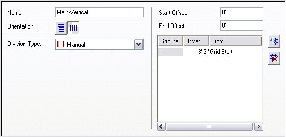
Main-Vertical Division

Sidelight-Horizontal Division
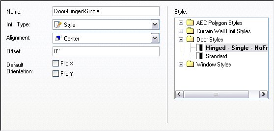
Door-Hinged-Single Infill
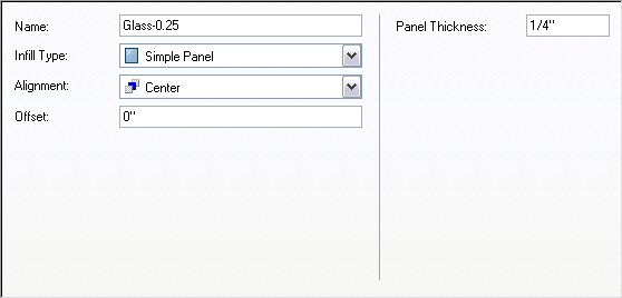
Glass-0.25 Infill
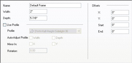
Default Frame Frame
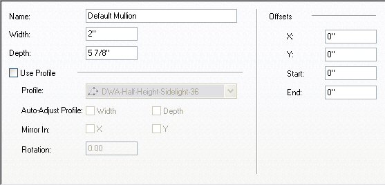
Default Mullion Mullion
The out-of-the-box Doors & Windows.Glazing.Glass.Clear material was assigned to the Glass-0.25 Infill; the Default Frame and Default Mullion components had the Doors & Windows.Metal Doors & Frames.Aluminum Frame.Annodized.Dark Bronze.Satin material assigned [mostly because it came in with the Hinged - Single Door, which has the Doors & Windows.Wood Doors.Ash material assigned to the door panel].
I renamed the Primary Grid to Door-Sidlight, managing to omit the "e" in "Sidelight" in my haste. The assignments for this grid are shown below. Note that a nested grid is assigned to the End cell. This "New Nested Grid" was renamed Sidelight [and spelled correctly, this time]. Also note that Default Frame is only assigned to the left, right and top - the bottom frame is omitted, as we do not want one at the door and the sidelight does not extend to the floor.

The Sidelight Grid assignments were made as shown below.

A 6'-6" wide x 7'-2" high instance of this Door Window Assembly style was inserted in an out-of-the-box Stud-3.625 GWB-0.625 Each Side wall. I changed to a SE Isometric view and turned on the infill markers by selecting the Door/Window Assembly, right clicking and choosing Infill>Show Markers from the context menu. With the Door/Window Assembly still selected, I right clicked and chose Infill>Override Assignment... from the context menu, and then selected the infill marker in the lower half of the sidelight cell. I chose the Remove Infill and Frames option in the Infill Assignment Override dialog and selected OK. I then transferred the Design Rules to the object [select Door/Window Assembly, right click, choose Design Rules>Transfer to Object] and then transferred them back to the style [with Door/Window Assembly still selected, right click, choose Design Rules>Save to Style... and then check Transfer Infill Overrides to Style in the Save Changes dialog and click OK]. These overrides are now part of this style and will be applied to all instances of this style. This style is illustrated on the left side of the image below. Notice that even though the bottom cell of the sidelight and its frame are turned off, the wall does not fill in below the sidelight. If you are only interested in a plan view of this assembly, you are essentially done [depending upon the cut plane height and the height at which you set the bottom mullion of the sidelight, you may need to add a manual cut plane to see the mullion]. But if you want to generate an elevation or do a 3D view/rendering, you will need to do one more thing to get the results shown on the right Door Window Assembly.
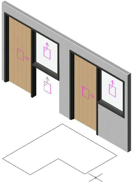
SE Isometric View ;

In order to get the wall to fill in under the sidelight, you will need to create a profile that describes the outline of the outer edge of the frames/mullions and the floor line, then assign it to the style. Draw a LWPOLYLINE in the desired shape. In the Style Manager, create a new Profile [under Multi-Purpose Objects], give it the desired name, then right click the profile name and choose Set From... on the context menu. Select the polyline and choose an insertion point; I chose the lower left corner [door side]. Note that assigning a profile will effectively fix the dimension of the Door/Window Assembly. You can change the width, and the profile will be scaled to match, but you will get undesirable 3D results - as the width is made less than that used when drawing the profile, the door mullion below the sidelight will start to disappear, and eventually the door will also be notched. As the width grows larger than the original profile width, the wall infill will fall short of the door mullion below the sidelight. In the sample file, I created a copy of the original style, then assigned the 6'-6" wide profile to it. This would allow me to make additional copies of the original style and assign profiles with different widths, if needed.
1 comment:
I found this page following a link from the Autodesk Discussion groups. It's just what I was looking for - thanks for posting it.
Post a Comment