December 27, 2014

Dynamo - Custom Node, 2 Char Zero Padding

Dynamo provides a way to modularize code, both to make it easy to reuse in future projects and to make it easier to follow the flow in the main routine. Creating a custom node is as easy as selecting the group of nodes that perform a particular function in a Dynamo file and choosing Edit > Create Node From Selection from the pull-down menus or pressing CTRL+D.

The image above shows the Coded Date Parameter graph with the custom nodes replaced with the underlying nodes. This works, but it occurred to me that I might want to reuse the conversion of an integer to a two-character, zero-padded string part in the future, By creating a custom node for that part of the graph, I can save the custom node (as a DYF file) to my Dynamo definitions folder, where it will be available in the left-sash Library. An added benefit is the simplification of the main graph.

Creating a Custom Node
  1. Select the nodes to be included in the custom node. Multiple nodes can be selected by holding down the SHIFT key as you select individual nodes or by clicking in an empty space in the graph and, while holding the left mouse button down, dragging to enclose the nodes within a window. Like AutoCAD, if your second drag point is to the right of the first, you will have a window selection that only selects nodes completely within the window; if your second drag point is to the left of the first, you will have a crossing window that will select nodes that are either completely or partially within the window.
  2. Select Edit > Create Node From Selection or press CTRL+D.
  3. In the Custom Node Properties dialog, enter a Name and a Description (tooltip) for your custom node. Then specify a Category, which determines where the node will appear in the Library. NOTE: You do not have to select from the existing categories; you can type in a category of your choosing. Use a period to separate the name of an upper level category from the name of a nested category. In the example shown, I created a new top level category for my own nodes called "DWK" (my initials) and a subcategory called "String" below that. Press OK to create the custom node.
  4. Observe that the selected nodes have been replaced by a custom node, and that a new tab has appeared in the workspace.
  5. Select the Integer to String - 2 Char Zero Padding tab to make it current, and then, in the upper right corner of the graph pane, select the top icon (dashed line square) to zoom to the extents of the graph.
    Notice that Dynamo added Input and Output nodes to the custom node graph, one Input for each "wire" leading into the selected nodes and one Output for each "wire" leading out of the selected nodes. These represent the inputs and outputs of the custom node. You can rename the labels (object and result in this example in the image above) that appear on the custom node by selecting the label and typing the desired name. I chose to rename the input label to integer and the output node to string.
  6. Assuming that your original graph worked, the custom node is now complete. All that remains is to save the node to a DYF file, in your Dynamo definitions folder. Select File > Save from the pull-down menus or press CTRL+S to save the file. The Save As dialog should default to the appropriate folder (in my case, C:\Users\dkoch\AppData\Roaming\Dynamo\0.7\definitions; substitute your user name and Dynamo version). Failure to save the file will likely result in an undefined node in the DYN file from which you created the custom node. If you try to close the custom node tab without saving, you will be alerted to the fact that there are unsaved changes.
Integer To String - 2 Char Zero Padding Node
This custom node expects to receive an integer input, and uses the ToString node (Core > Builtin Functions > ToString) to convert the integer to a string. This string is then sent to three different nodes:
  • A String.Length node (Core > String > Actions > Length) determines the number of characters in the string. A Number node (Core > Input > Number), set to 1.000, is compared to the string length by a != [Not Equal] node (Operators > !=), which will return true if the string length is anything but 1 and false if the string length is one.
  • A String.Concat node (Core > String > Actions > Concat) concatenates the outputs of a String node (Core > Input > String), set to "0", and the output of the ToString node. This creates the potential zero-padded condition.
  • An If node (Core > Logic > If) also receives the output of the ToString node, in its true input. The If node is used to determine what string will become the output of the custom node. If the result of the != node, which is fed to the test input of the If node, is true (string is not one character in length), then the original string from the ToString node is passed through as the result, since it is the input for the true input of the If node. If the original string is one character in length, then false will be passed to the test input of the If node, and the results of the String.Concat node, which is passes to the false input of the If node, will be passed through.
The net result is that if a single-digit integer is the input of the node, it will be converted to a string and have a single zero character added at the front of the string. Any other length string will be passed through "as is." Since the input to this custom node is an integer representing a month or a day, the input will only have one or two digits, and this node will provide the desired zero-padding to yield a two-character string in all cases. Any future reuse of this node would require the main graph to assure that the integer input would be in the range of 0 to 99 for a two-character result.

After getting this to work, it occurred to me that it would be more useful to have a custom node that could handle zero-padding to any specified number of characters. But since this node satisfied the needs of the immediate task, I chose to save creating such a custom node as a future task.

December 23, 2014

Dynamo - Custom Plot Stamp

Here is an example of using Dynamo to do two things that you cannot do natively in Revit®: convert one data type to another (in this example, converting integers to strings) and concatenating multiple strings into one string. The inspiration for creating this Dynamo file was this thread in the Autodesk Revit Architecture Discussion Group. The request was a wish for the ability to created a customized date stamp, showing just a numeric date in yyyymmdd format, with three "random" numerals in front and in back, to "disguise" the actual purpose of the string, while allowing those who know to see when the plot was made. The comparison was to what you can do with Fields in AutoCAD®. While the Dynamo file, by its very nature, cannot provide the automatic update that AutoCAD Fields provide, it can standardize the formatting of the custom date stamp, and make manual updates easier than editing the value in the Project Properties dialog.

NOTE: If you work in a "shared" environment, please consult with your BIM Manager and/or co-workers before modifying an office- or project-standard shared parameters file, project template or title block family.

The first stage is to set things up in Revit. This is done the same way that you would do it to set up a manually updated title block parameter. A quick summary of that follows:
  1. Create a shared parameter to be used to hold the custom plot stamp text, if you do not already have one. On the Manage ribbon tab, on the Settings panel, select the Shared Parameters tool. Set the appropriate shared parameters file current, select the appropriate parameter group and create the parameter. Set the parameter type to Text and add a tooltip description (2015 release or later), so that others will know the purpose of the shared parameter.
  2. Add a Project Parameter to your project (for an existing project) or your project template(s) (for future projects). Choose the Shared parameter radio button and then choose the Select button to choose the shared parameter created in Step 1. Select a group under which the parameter will be placed, if the initial "Text" group is not to your liking. Choose the Instance radio button and set the Category to Project Information.
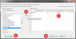
  3. Edit your title block family or families. In each one, add a Label to display the value of the shared parameter created in Step 1. On the Create tab, on the Text panel, choose the Label tool. In the Edit Label dialog, select the Add Parameter tool in the lower left, and add the shared parameter created in Step 1. Select the newly added Shared Parameter in the Category Parameters list box and select the Add parameter(s) to label tool (green arrow icon). Change the Sample Value for the parameter, if desired, then select OK. Fine tune the location and orientation of the label in your title block family, then save or save as the family, if desired, and load the title block family into your project and/or project template file.
At this point we have a Project Parameter that can be set in one place for the entire project, and which will display in the label added to the title block family(ies).
You could open the Project Properties dialog (Manage ribbon tab, Settings panel, Project Information tool) and manually enter a value (or select an instance of the title block and click on "?" for the label you added and type the value in there. While that is a perfectly valid workflow, by using Dynamo, you can update the value in a consistent manner. The image below shows the overall Dynamo graph, followed by an explanation of the parts.
  1. Three stages of nodes generate the pieces of the numeric date in yyyymmdd format. The DateTime.Now node (Library path = Core > DateTime > Now) generates the current system time and date. In the image below, all of the nodes have a "watch toggle" and they are toggled on, so that the value of the node is displayed below the node. We only need the year, month and day, so the value of that node is passed to the DateTime.Components node (Core > DateTime > Actions > Components), which generates separate numeric values for the listed components. The third stage consists of one ToString node (Core > Builtin Functions > ToString), which converts the numeric year output from the DateTime.Components node to a string (text), and two custom nodes named Integer To String - 2 Char Zero Padding, which convert the month and day output from integers to strings while also assuring a two-character result by adding a "0" at the front of any single-character strings. These custom nodes were created from a number of out-of-the-box nodes; I will discuss the creation of custom nodes and show the inner workings of these nodes in a future article.
  2. The random three-digit prefix and suffix are generated by two similar sets of nodes. In each, two Number nodes (Core > Input > Number) establish the range of double-precision real number values that the Math.Random node (Core > Math > Actions > Random(value1:double, value2:double)) uses when generating a double-precision random number. I chose 100 and 999 as the boundaries to assure I would get a three-digit (whole number part) result. Note that I had chosen three decimal place display for numbers in Dynamo at the time these screen captures were take, so all numeric values, even integers, display with three decimal places (Settings pulldown menu > Number Format > 0.000). The output of the Math.Random node is passed through the Math.Floor node (Core > Math > Actions > Floor), to convert the double to an integer (rounding down to the next integer value, effectively truncating any fractional amount), prior to using another ToString node to convert the integer to a text string.
  3. We now have all of the strings we need to create the text value for the plot stamp. A String.Concat node (Core > String > Actions > Concat) takes the five strings (random prefix, year, month, day and random suffix) and combines them into one string. The String.Concat node starts out with one input, string0; you can use the + button to add more inputs and the - button to remove inputs as required by your application.
  4. Now that we have the nodes required to generate the string we want for the plot stamp, we need to get that value out of Dynamo and into the DateCode parameter in Revit. To do that, we first need to get the ProjectInfo element, which holds the Project Information parameters. Two nodes will do that for us. First, the Categories node (Revit > Selection > Categories) allows you to select from a list of all of the built-in Revit categories, one of which is ProjectInformation. Passing that category to the All Elements of Category node (Revit > Selection > All Elements of Category) selects the ProjectInfo element for the current project. These two nodes do not have a "watch toggle", so I included a Watch node (Core > View > Watch) in the overall graph (not shown in the image below) to view the result of the All Elements of Category node. This is not needed for the Dynamo function to work.
  5. The Element.SetParameterByName node (Revit > Elements > Element > Actions > SetParameterByName) is where our value gets pushed into the Revit project. It takes three inputs, the element we acquired in Step 7, a string from a String node (Core > Input > String) into which the name of the parameter to be set has been entered (case sensitive, enter the name exactly as it appears in Revit), and the value to be set, which is the concatenated string from Step 6.
With all of the elements in place, and the graph saved to a Dynamo file (DYN extension), it is simply a matter of pressing the Run button to initiate the program. Dynamo will generate the prefix and suffix numbers, gather up the year, month and day numbers, convert them all to strings and combine them into one string. The Project Information element will be accessed and the string value will be used to set the value of the DateCode parameter.

This may seem like a lot of work, compared to typing fourteen numbers in a dialog box, and if you only ever use it one time, it is. But you can save the Dynamo file and every time you are about to plot, simply start Dynamo, open the file and select the Run button.

In this admittedly simple example, you can see how easy it is to write a program in Dynamo and have that program interact with Revit. Dynamo takes care of all of the hard work of interfacing with the API; all you need to do is connect the nodes.

December 19, 2014

Dynamo

I had the good fortune to be able to attend Autodesk University this year, and without initially intending to do so, ended up with the majority of my classes centered on Dynamo. Dynamo is an open-source add-in that works with Revit (and Vasari) and provides a graphical means of creating custom programming for Revit. The architect side of me appreciates the graphical interface; the long-time AutoCAD®/AutoCAD® Architecture customization side of me (AutoLISP®, VBScript in formula properties) appreciates the ability to do things and process data in ways not accommodated by the out-of-the-box commands and features.

I have had a long-time desire to become familiar with the Revit API and explore the possibilities available there, but a combination of a lack of significant stretches of dedicated time and being somewhat intimidated by the amount of things I would have to learn just to get started have conspired to keep me from starting that journey. From what I have seen so far of Dynamo, there is a much lower entry barrier, and I am excited to learn more and apply that knowledge to real-world, useful projects.

As I discover things (or have others show them to me), I expect I will be documenting them here. Until then, here are links to the Dynamo website and other related resources.

Dynanmo Website
Dynamo Downloads
Dynamo Tutorials
Dynamo Blog
Dynamo Gallery
Dynamo Community (discussion forum)

I would also like to express my thanks to Zach Kron, Marcello Sgambelluri, Nathan Miller, Ian Keough, Michael Hudson, Andrea Vannini and Nuri Miller, who taught one or more of the classes I took at Autodesk University this year. Check out the materials that are available on line:

AB6644: Dynamo: The Future is Wide Open - Zach Kron (session recorded)
AB6542: Explore the Possibilities with Computational BIM - Ian Keough (session recorded)
AB6557: Practically Dynamo: Practical Uses for Dynamo Within Revit - Marcello Sgambelluri (session recorded)
AB6545-L: Dynamo for Dummies: An Intro to Dynamo and How It Interacts with Revit - Marcello Sgambelluri
AB5482: The Great Dynamo Dig: Mine Your Revit Model with Computation - Nathan Miller (session recorded)
AB5492: White-Glove Packaging: Creating Custom Dynamo Nodes - Nathan Miller
AB6495: Dynamo Hero: Using Revit Scripting Tools to Optimize Real-World Projects - Michael Hudson and Andrea Vannini
SD5132-L: Automation Prototyping: A Side-by-Side Comparison of Dynamo and the Revit API - Nuri Miller

December 11, 2014

AutoCAD: Automation Error. Description was not provided.

While I am certain that the error message in the title above will be issued for any number of reasons, I came across this when some users were trying to run a custom AutoLISP® routine that draws an area to be enlarged "box". Until yesterday, I was unable to reproduce the issue on my own computer, making it hard to figure out what was causing the error. Having determined at least one cause for this error message, I decided to document it here.

Finally running into the error myself yesterday, I was able to use the VisualLisp IDE to step through the main routine and determine that the crash was occuring during a call to a subroutine that returns a list of the Layer Keys in the current Layer Key Style. While I would like to think of myself as a relatively competent AutoLISP programmer, there are definitely areas where my skills and experience are thin; error handling routines are one such area. At the time I wrote that subroutine, I was not aware that the out-of-the-box (AecLayerKeyList) function (defined in AecLMgrLISP.arx) would do what I wanted from my subroutine (I was likely confused by the description of the routine as returning "a resbuf list of strings"), so I wrote my own, with no error handling. It turns out that at some point in the past, our office standard Layer Key Style ended up with a corrupt Layer Key. Attempting to read the name of this layer key results in the "undescribed" error. Both the (AecLayerKeyList) function and the Style Manager are capable of handling the error. Style Manager just omits the corrupt Layer Key; the (AecLayerKeyList) function includes the name as an empty string (""), which is not valid input for the name of a Layer Key.

Overwriting the "bad" Layer Key Style with one that does not have the corrupt Layer Key resolves the error and allows the area-to-be-enlarged routine to run. That was much easier than adding error handling to my routine, and should probably be done in any event.

November 30, 2014

ACA: AEC Modify Tools, Part 4, AEC Subtract

First post in series [AecLineworkExtend].
Previous post in series [AECLineworkDivide].

The AecLineworkSubtract command is available on the Home ribbon tab, on the Modify panel flyout, by selecting the Subtract tool from the Merge/Subtract flyout. If the Subtract tool is not the displayed tool on the Merge/Subtract flyout, select the right side of the split button (down arrow icon) to deploy the flyout and choose the Subtract tool. Or, with no command active, you can right click in the drawing window, and choose AEC Modify Tools > Subtract from the context menu.

The AecLineworkSubtract command can be used to subtract (delete) parts of linework, AEC Polygons, Mass Element Extrusions that have an embedded profile, Spaces and Hatches as well as from Block References which contain any of these objects. There are two options for specifying the extents of the subtraction area:
  • Select one or more items in the drawing, which form at least one closed loop. Any single closed item will work (closed Polyline, Circle, Ellipse, AEC Polygon, Mass Element or Space), as will any combination of objects that, combined, form at least one closed loop.
  • Press the ENTER key when prompted to select items to subtract, and then define a subtraction rectangle by selecting opposite corners of a rectangle. The rectangle will have sides parallel to the X- and Y-axes of the current UCS.
If you select objects to specify the subtract border, you will asked if you want to erase the selected items. The default response is No. The Screencast embedded below shows the AecLineworkSubtract command in use on various object types. As with the AecLineworkTrim and AecLineworkDivide commands, if the original object was a closed object, a closed obejct will result, with Circles becoming closed Polylines.
Here are some additional notes regarding the AecLineworkSubtract command:
  • MText, Text, Ellipses and Ellipse Arcs cannot be added to the selection set of objects from which to subtract a portion.
  • Ellipses and Ellipse Arcs can be selected as (part of) a boundary defining the area to subtract.
  • Mass Elements with a shape other than "Extrusion" and Mass Element Extrusions that have an external Profile can be selected as objects from which to subtract, but will not affected by the AecLineworkSubtract command. These types of Mass Elements can be used to define the area to subtract.
  • If a Block Reference is selected as an object from which to subtract, only those nested objects within the block on which the AecLineworkSubtract command works will be affected.
  • Attributes within a Block Reference will not be affected by the AecLineworkSubtract command.
  • If a Block Reference is selected as an object from which to subtract, it has subtractable nested elements and it is the only instance of that Block Reference in the drawing, then the original block definition will be redefined to include the effects of the subtraction. If at least one instance of the Block Reference remains unaffected by the subtraction, then the original block definition will remain unchanged and the affected instance(s) will become instance(s) of new, anonymous block definition(s).
  • Multi-View Blocks can be selected as an object to have a part subtracted, but will not be affected by the command.
  • If the area to subtract effectively splits an object into two or more separate pieces, the result depends upon the selected object. Closed Polylines and Circles will result in two (or more) separate Closed Polylines. Hatches, Mass Element Extrusions (embedded Profiles), AEC Polygons and Spaces will result in one object, with two (or more) separate, non-contiguous regions.
  • Associative Spaces, Walls, Doors, Windows and Door/Window Assemblies can be selected as items from which to subtract, but will not be affected by the command. Non-associative Spaces do work with the AecLineworkSubtract command.
  • Subtracting from an associative Hatch will result in a non-associative Hatch, regardless of whether or not the boundary of the Hatch is included in the subtraction.
  • If an object in the subtract selection set is entirely within the subtraction boundary, it will be deleted.

As with the AecLineworkDivide command, there are object types and combinations of objects within a Block Reference that I did not test. If you are thinking of using the AecLineworkSubtract command in a situation that you have not done so previously, you may want to use the Mark option of the UNDO command to place one or more UNDO Marks prior to using the command, so that you can easily UNDO Back to the point before the command was used if you get unexpected results.

Next post in series [AECLineworkObscure].

November 23, 2014

ACA 2015: Cannot invoke (command) from *error* without...

Several people in the Autodesk AutoCAD® Architecture General Discussion Group have experienced problems when trying to run AutoLISP routines in which an error condition is encountered. Instead of the usual, often helpful, error message at the Command: line, this error shows up, instead:
Cannot invoke (command) from *error* without prior call to (*push-error-using-command*).

This appears to happen even when the first thing you do in a drawing is evaluate a LISP expression with an error, for example, by typing (alert 1) at the Command: prompt and then pressing ENTER.

If you were hoping for a more informative error message, so you could try to work out what went wrong, you will want to reset the initial definition of the *error* function to what it should be:
(defun *error* (msg) (princ "error: ") (princ msg) (princ))

One way to get this code loaded into every drawing you open would be to include it in your ACADDOC.lsp file (if you have one; if not, you can create one). This file needs to be somewhere in the AutoCAD Search path (and be the first on of that name found); if your firm has a standard ACADDOC.lsp file and you do not have rights to edit it, you may want to discuss having this code added to it with your CAD Manager. You will also want to have the folder in which the ACADDOC.lsp is placed be designated as a Trusted Path (Files tab of Options dialog) if you have SECURELOAD set to 1 to avoid the nag dialog about loading it. If SECURELOAD is set to 2, you have to have the ACADDOC.lsp file in a Trusted Path folder, or the file will not load at all.

There are other ways to get this code loaded with each file, if using ACADDOC.lsp does not work for your situation. The easiest would be to open Notepad and paste the code above into it, then save the file with a name of your choosing and a LSP extension, again, to a folder that has been designated as a Trusted Path. Then add that file to your Startup Suite in the Load/Unload Applications dialog (APPLOAD command).

I am not sure why the *error* function is not properly initialized, but running the above code when opening a drawing or creating a new drawing will resolve this issue and give you the expected error messages.

November 09, 2014

ACA: AEC Modify Tools, Part 3, AEC Divide

First post in series [AecLineworkExtend].
Previous post in series [AecLineworkTrim].

I decided not to wait six years between posts on the AEC Modify tools this time. Today's featured command is the AecLineworkDivide command. This command can be accessed on the Home ribbon tab, on the Modify panel flyout or from the right-click context menu (no command active), by choosing AEC Modify Tools > Divide.

The Screencast embedded below shows the AecLineworkDivide command in action. As shown in the Screencast, the command works on linework, Mass Element Extrusions that have an embedded profile, AEC Polygons, Spaces and Block References that contain at least one of the previously mentioned objects. 11/23/2014 Update: "Linework" includes Hatches.

You can specify the dividing line in two ways (just as you could do so for the AecLineworkExtend and AecLineworkTrim commands), either by selecting two points, as was done in the Screencast, or, by pressing the ENTER key when prompted for the first point, and then hovering over an existing line in the file and left clicking when the desired dividing line is highlighted. No matter which method you choose, the dividing line is treated as being infinite in length; the endpoints need not be outside the extents of the selection set.

When a closed item is divided by the AecLineworkDivide command, the resulting objects are also closed, whether the objects are main objects or nested within a Block Reference. A divided circle results in two closed Polylines. A closed Polyline results in (at least) two closed Polylines. An open Polyline results in at least two polylines, and possibly many more, if the dividing line crosses the Polyline multiple times, as it does in the example in the Screencast.

Here are some additional things of which to be aware when using the AecLineworkDivide command:
  • MText, Text, Ellipses and Ellipse Arcs are not dividable and cannot be added to the selection set for the AecLineworkDivide command.
  • Mass Elements with a shape other than "Extrusion" and Mass Element Extrusions that have an external Profile assigned are not dividable. If you include these types of Mass Elements in the selection set of the AecLineworkDivide command, the entire object will be duplicated, even if the dividing line does not intersect the Mass Element.
  • If you divide a Block Reference with dividable nested objects that has just one instance in the file, then the original block definition will be redefined as the objects on one side, and an anonymous block will be created for the objects on the other side. If there are other instances of a Block Reference that are not in the selection set, then the original definition will be left as is, and anonymous block definitions will be created for both sides of the divided Block Reference.
  • When undividable items are present in a block reference that is being divided, the undividable elements will be included in the block definition of both of the newly created blocks.
  • Weird things happen when you divide an attributed block. If there are no dividable objects, the attributed block may be "replaced" with an anonymous block, which may not be annotative even if the original block was. If there are dividable items in the attributed block, then you will likely get two blocks, with the attributes in both, although in my tests the actual instance in the file of one of the blocks did not have the attributes, but inserting another instance of it did result in attributes.
  • Multi-View Blocks are selectable, but will not actually divide, even if the underlying view block contains dividable graphics. The Multi-View Block will duplicate, however (in place), even if it is not cut by the dividing line. This is actually quite handy in the case of a Multi-View Block Space tag, where you are dividing the Space as well. If you include both the Space and the Tag in the same AecLineworkDivide command selection set, then each of the two Spaces created by the divide will be tagged by one of the two Tags generated. You will still have to manually separate the two Tags.
  • In some cases where the object to be divided is irregularly shaped, the divide may create more than two potential objects, for example, a U-shaped closed Polyline or Space divided across the arms of the "U". For the Polyline, you will get three closed Polylines. For the Space, you will only get two Spaces, one of which will have two non-contiguous sub-areas.
  • Walls, Doors, Windows and Door/Window Assemblies do not work well with the AecLineworkDivide command. These items will not be split (not even Walls), but they will duplicate in place, creating, in the case of Walls, cleanup nightmares, and duplicate objects in the other cases. I would not recommend including these items in the selection set of the AecLineworkDivide command.
  • Associative Spaces are also not good candidates for the AecLineworkDivide command. The entire Space will be duplicated, and both will be associative to the same boundaries. I cannot think of a scenario where that would be the desired end result. Non-associative Spaces work just fine, as seen in the Screencast.
  • 11/23/2014 Update: If you select the boundary of an associative Hatch, select the Hatch as well, if you want the Hatch to remain associative and to be associative to the trimmed boundary. Otherwise, the Hatch will become non-associative and retain its extents.

I am sure I have missed some object types or some combination of objects nested inside a Block Reference that have unexpected results when the AecLineworkDivide command is applied. I suggest using the Mark option of the UNDO command to set one or more UNDO Marks prior to using the AecLineworkDivide command in unfamiliar situations, so that you can easily UNDO Back to the Mark if things are not to your liking. That said, there are cases where this command can be handy, when used appropriately.

Next post in the series [AECLineworkSubtract].

October 30, 2014

New Features Links

From time to time, questions are raised as to what new features have been added between Release X and Release Y. I try write about the new features at the time of each release (or, at the least, the new features that interest me), but have never collected links to all of those in one place. To make it easier for me to refer to them, and for others to find them, this post will become an index to the new features posts. I will place a link to it under the Oldies But Goodies section at the right side of the blog.

ACA 2018
ACA/AMEP 2018: New Features Part 1 - External Reference Improvements
ACA/AMEP 2018: New Features Part 2

ACA 2017
ACA 2017: Grip Editing of a Roof Object Outline
ACA 2017: CReate type Command Option
ACA/AMEP 2017: Styles Browser Enhancements

ACA 2016
ACA 2016: Quick Notes
ACA/AMEP 2016: Styles Browser Part 1
ACA/AMEP 2016: Styles Browser Part 2
ACA/AMEP 2016: Section Enhancements
ACA/AMEP 2016: Property Visibility Override

ACA 2015
ACA 2015 - New Look
ACA 2015 - Style Import
ACA 2015 - Version Management in Project Navigator
ACA 2015 - Visual Comparison
ACA 2015 - Command Preview
AutoCAD 2015 - Cursor Badges
ACA 2015 - Highlighting and Selection Preview

ACA 2014
ACA 2014: Property Set Defintion Auto-attach
ACA 2014: Command Line Search
ACA 2014: Door and Window Placement
ACA 2014: Tools from the DACH Extension
ACA 2014: Additional New Features/Improvements

ACA 2013
ACA 2013 - Grouping and Subtotals in Schedule Tables
ACA 2013: Object Display Enhancements Part 1
ACA 2013: Object Display Enhancements Part 2
ACA 2013: Object Display Enhancements Part 3
AutoCAD 2013 - Command Line Enhancements

ACA 2012
ACA 2012 New Feature - Corner Windows
ACA 2012 Enhanced Feature - Column Grids
AutoCAD 2012 New Feature - In-Canvas View Controls
AutoCAD 2012 New Feature - AutoComplete

ACA 2011
AutoCAD® Architecture 2011 Overview
Selection Cycling
ACA 2011 - Opening Location Changes - Part 1
ACA 2011 - Opening Location Changes - Part 2
ACA 2011 - Opening Location Changes - Part 3
ACA 2011 - Opening Location Changes - Part 4

ACA 2010
AutoCAD® Architecture 2010 - Editing Wall Cleanup In Place
More AutoCAD® Architecture 2010 Features
AutoCAD® Architecture 2010 - UI Changes, Part 1 - The Application Menu
AutoCAD® Architecture 2010 – UI Changes, Part 2 – Resizing the Ribbon
AutoCAD® Architecture 2010 - UI Changes, Part 3 - The Ribbon, Home Tab
AutoCAD® Architecture 2010 - UI Changes, Part 3.5 - Tool Palette Command Buttons Alert
AutoCAD® Architecture 2010 - UI Changes, Part 3.6 - Fixing Context Menu Paste Commands
AutoCAD® Architecture 2010 – UI Changes, Part 4 – The Ribbon, Insert Tab
AutoCAD® Architecture 2010 – UI Changes, Part 4.5 – Ribbon Tools
AutoCAD® Architecture 2010 – UI Changes, Part 5 – The Ribbon, Annotate Tab
AutoCAD® Architecture 2010 – UI Changes, Part 6 – The Ribbon, Render Tab
2010 File Format Change
AutoCAD® Architecture 2010 - UI Changes, Part 7 - The Ribbon, View Tab
AutoCAD® Architecture 2010 - UI Changes, Part 8 - The Ribbon, Manage Tab

ACA 2009
AutoCAD Architecture 2009 - Part 1
AutoCAD Architecture 2009 - Part 2
AutoCAD Architecture 2009 - Part 3
AutoCAD Architecture 2009 - Part 4
Space Generation in ACD-A 2009 with AutoCAD® Object Boundaries

ACA 2008
No More LTSCALE/PSLTSCALE Problems!
Annotative Tags With Leaders in ACA 2008
I appear to have been distracted in 2007, and did not write extensively about the new features in ACA 2008. You can read about three 2008 features that were at the top of Matt Dillon's list in his blog, here.

ADT 2007
ADT 2006 Tags
Enhanced Property Data Features in ADT 2007, Part 1
Enhanced Property Data Features in ADT 2007, Part 2
Enhanced Property Data Features in ADT 2007, Part 3
Enhanced Property Data Features in ADT 2007, Part 4
Enhanced Property Data Features in ADT 2007, Part 5
ACA 2008/ADT 2007: Setting a Different Property Data Format in a Formula Property

ADT 2006
ADT 2006 Tags
ADT 2006 Tags Illustrated
Formula Property Interface Improved in ADT 2006
Selection Previewing in ADT/AutoCAD 2006
Selection Previewing Update

October 18, 2014

Renaissance Revit - A Partial Review

Some time ago, I purchased Renaissance Revit® - Creating Classical Architecture with Modern Software, by Paul F. Aubin. Since then, I have been struggling with finding time to work my way through the tutorials in the book. Having finally made it into Chapter 6 (of 14), and completed the Tuscan column, it occurred to me that I should write something about it now, rather than waiting until I had gotten through the entire book (whenever that may be).

The intent of the book is to provide intermediate and advanced lessons in the use of the Revit Family Editor. The vehicle in which these lessons is delivered is classical architecture, but whether or not your design work involves use of the classical orders, all but the most highly experienced Family Editor users will find numerous techniques and tips that will be quite useful in the families that you create for your work. The book assumes a basic understanding of Revit. Chapter 2 provides an overview of basic family editor skills for anyone new to the Family Editor.

The book starts out by laying a foundation of skills needed throughout the rest of the book. A brief discussion of the classical orders and the strategies that will be used is followed by a review of core Family Editor skills. Since the classical orders are all based on scale and proportion, and because the SCALE command in Revit does not work on many elements, including 3D geometry, Chapter 3 introduces methods for enabling scaling and maintaining proportions through parameters. Anyone who has ever struggled with parametrically controlling curves and/or angles in a family (which includes me) will find Chapter 4, which covers constraining curves, well worth the cost of the book.

Chapters 5 and 6 apply the lessons learned to the creation of content for the Tuscan Order. All of the content is tied back to the diameter at the base of the column by formulas, and, for the columns, the base diameter is determined by the column height. One family, with just two types (Without Pedstal and With Pedestal), produces columns of any size, scaled up or down based on the column height.

The Screencast below shows the Tuscan column in action.

I have no hesitation in highly recommending this book to anyone seeking to improve their knowledge of the Revit Family Editor, particularly those who have made some basic families and are looking to learn more advanced techniques. If you can afford the higher cost, the color edition enhances the learning experience. But if cost is an issue, the content in the black and white version is the same. Instructions for downloading a dataset from the author's website are provided. You can download either just the files needed to start each lesson, or a larger package that also includes catch-up and completed files. The catch-up files let you jump in at intermediate points in a lesson, if desired (or can be used to compare against your file, to see if you executed the tutorial up to that point correctly).

FULL DISCLOSURE: I know the author and have worked with him in a paid capacity on other books (the 2010 and 2011 editions of his book for AutoCAD® Architecture). I did not have anything to do with the production of this book (other than responding to a survey that Mr. Aubin conducted) and paid the full retail price for my copy of the book.

September 13, 2014

ACA - Creating a New Tool Palettes Set

I came across this somewhat older article in the Autodesk® Knowledge Network recently: Creating a New Tool Palettes Set. Written for AutoCAD® Architecture 2011, I made a mental note to look into this when I had some time, because creating additional Tool Palettes File Locations is something that I do on occasion (more often than most users, no doubt). See the "Note" at the end if you are interested in why.

In the past, I had found that if I added a new folder path to the Tool Palettes File Locations node on the Files tab of the Options dialog and bumped it to the top of the list so that it would receive any newly added palettes, that the folder remained empty, and that added palettes went to the first editable location further down on the list. I did discover that if I copied the AcTpCatalog.atc file and all of the subfolders from a working palette location to my new folder, that new palettes would go into this location. Not wanting to duplicate palettes and images that were in the location from which I copied the AcTpCatalog.atc file and not wanting to have to delete them every time I set up a new tool palette set, I eventually deleted all of the palettes from a copied set (except for one, blank palette) and then set that aside as a "starter" location to be copied when making a new set.
Years later, I discovered that by editing AcTpCatalog.atc with an XML editor, I could strip out the blank palette as well. I find Microsoft's free XML Notepad 2007 to be quite useful for tasks such as this. It is also great if you move content location and need to edit the paths stored in a lot of tools, as you can search for/replace one string with another.

So, I was quite interested in the procedure in this article, but, since I had been doing what the article said to do and had not had success in the past, I wondered what I was doing wrong. The clue to that is in the note in Step 7. Unfortunately, while what the note says is correct (if the location you add already has a tool palette set, a new one will not be created), it does not go far enough. The procedure and this note assume that you only have one path specified under the Tool Palettes File Locations node. If you have more than one path, and any one of the paths have a tool palette set, adding a new, empty folder and moving it to the top of the list will not generate a new tool palette set in that empty folder. You have to remove all folders that have a tool palette set in order to have ACA generate a new tool palette set in the new (top of list) folder. If you would prefer not to mess with the Tool Palettes File Locations paths set in your working Profile (removing them will remove the palettes from any Tool Palette Groups you may have set up), simply create a new Profile for the purpose of generating an empty tool palette set. In the new Profile, remove all paths except the one pointing to your new, empty folder. When you click OK to dismiss the Options dialog, a new tool palette set will be generated, with one, blank tool palette.
You can delete the new Profile afterwards, if you have no further use for it, and then add the new folder to your working Profile's Tool Palettes File Locations. That is much easier than copying an existing tool palette set folder and then deleting the palettes defined therein. And, having done this once, you can make a copy of that folder and reserve that as a seed folder that you can copy for future new palette sets.

Note:
I typically have a long list of "local" paths under the Tool Palettes File Locations node in my ACA profiles, as I have found it makes it much easier to bring these into a new release if they are not all jumbled together along with the out-of-the-box palettes in the WorkspaceCatalog (Imperial) [or Workspace Catalog (Metric) or Workspace Catalog (Global), if you typically use one of those] that is present on initial installation. [This is based on installing the United States English language content. You may have one or more differently named locations, and may not have one or more of these, depending upon your location and the content options you have installed.]

While I do have a custom, personal catalog into which I put "finished" palettes, and could transfer the palettes that way, I also have a lot of custom, on-the-fly palettes which I like to bring along, and I find it easier to keep these as editable local palettes, not linked to a catalog. And, as Design Technology Manager, I also need to be able to edit the tool catalog content for all of the disciplines at my firm. The end users typically access these palettes by directly including the path to the network-based Tool Catalog in their Tool Palettes File Locations. But in case some are i-Dropping refreshable palettes into their workspaces, I have a profile in which I do the same, so that I can edit the linked tool and copy it back and have it replace the previous tool. This maintains the order of the tools on the palette better than deleting the old tool and replacing it with a new one. I also like to keep each discipline's palettes in a separate Tool Palettes File Location, so that I can modify my profile to show just that location when doing the edits, to avoid confusion over i-Dropped and directly included versions of the same palette.

One last thought: The image above shows my Tool Palettes File Locations in ACA 2010. The folders that start with "toolpalette - " (actual folder name starts with "ToolPalette - ", but ACA does not keep the capital letters captialized) are custom locations I have added for various groups of tools. For reasons lost to the mists of time, I started the names of my locations that way, rather than with "WorkspaceCatalog". (Perhaps ADT 2004 did not use "WorkspaceCatalog" for the default folder names, or perhaps when working with the new-to-2004 feature back then, I confused that with the Tool Catalogs that also hold the out-of-the-box tool catalogs?) There is an out-of-the-box folder in the Support folder under your user name that is named "ToolPalette". This holds the out-of-the-box vanilla AutoCAD palettes and is not included as a path under Tool Palettes File Locations in the ACA Profiles (but is used in the "AutoCAD" profile, if you chose to create that when you installed the program).

September 06, 2014

AutoCAD - Object Snap Tracking and Command: Line Docking Status

There is an issue in AutoCAD® with Object Snap Tracking when the Command: line is undocked and either Dynamic Input is disabled, or, if enabled, the Pointer Input component of dynamic input is disabled. Under these circumstances, when you acquire a point, and move the cursor to a position where you have a tracking line active, when you start to type the distance you want from the tracking point, the tracking line disappears from the screen, and if you press ENTER after typing the distance, the resulting point will not be where you want it.

Three ways to avoid this:
  1. Dock the Command: line.
  2. If you like your Command: line undocked, turn on Dynamic Input (if off) and verify that Pointer Input is enabled. See NOTE below.
  3. If you really do not like having Pointer Input enabled, you can leave it disabled (leave Enable Dimension Input where possible enabled and keep Dynamic Input turned on), but after you type in the distance value for the offset from the tracked point (and the tracking line has disappeared), BEFORE you press the ENTER key, move the mouse slightly to reactivate the tracking line, and THEN press the ENTER key.
The Screencast below shows several attempts to use Object Snap Tracking to locate the starting point of a Line 10'-0" at 0 degrees from the existing intersection of two lines:
  1. Undocked Command: Line, Dynamic Input turned off. [Fail]
  2. Docked Command: Line, Dynamic Input turned off. [Success]
  3. Undocked Command: Line, Dynamic Input turned on, Pointer Input disabled. [Fail]
  4. Undocked Command: Line, Dynamic Input turned on, Pointer Input enabled. [Success - notice that tracking line does not disappear when typing offset distance]
  5. Undocked Command: Line, Dynamic Input turned on, Pointer Input disabled. [Success - because mouse was nudged after offset distance was typed, restoring tracking line, before ENTER was pressed]

NOTE: If you want to minimize the amount of time that the Pointer Input box appears on screen, you can right click on the Dynamic Input tool on the Application Status Bar and choose Dynamic Input Settings from the context menu. In the Drafting Settings dialog that appears, on the Dynamic Input tag, choose the Settings button in the Pointer Input area and choose the As soon as I type coordinate data radio button in the Visibility area.
You can also set the DYNPIVIS System Variable to 0 .

I would like to see Autodesk address this deficiency, but from Discussion Group posts, it appears to have been around for quite a few releases, so you may want to make note of the workarounds above.

September 04, 2014

ACA 2015 - Highlighting and Selection Preview

Long-time users of Autodesk® AutoCAD® and Autodesk® AutoCAD® Architecture are likely familiar with the HIGHLIGHT system variable, which enables/disables highlighting of selected objects. Back before grips, enabling it was the only way to visually keep track of what objects were currently selected. The 2015 release adds a new effect to both selection highlighting and selection preview - the "glowing line" - along with the traditional dashed line (dashed and thickened for selection preview). Hardware acceleration has to be enabled in order for the glowing line effect to be displayed. The SELECTIONEFFECT System Variable allows you to choose between the two options (see below for details).
Selection Highlight with Glowing Lines

Selection Highlight with Dashed Lines


Selection preview allows you to see what object would be selected if you completed the current selection action. So, the object under the cursor that would be selected if you left clicked will get the selection preview as you move your cursor around the screen. If you start a selection rectangle or lasso (window or crossing) or a selection fence, the selection preview is applied to all objects that would be selected if you ended the selection method at that moment. The PRESELECTIONEFFECT System Variable (see below for details) allows you to choose between glowing lines and dashed/thickened lines. When glowing lines are enabled, you can distinguish already selected items from selection preview items by the color of the glow: a selected item will have a blue glow whereas an item that has selection preview applied have a gray glow.
Selection Preview with Glowing Lines

Selection Preview with Dashed and Thickened Lines


Depending upon your viewing preferences, machine capabilities and drawing size and complexity, you may find selection preview disruptive to your workflow. You do, however, have more control over this feature than just on or off. Selection preview can be globally turned on or off independently for two different conditions: when a command is active and when no command is active. This is controlled by the SELECTIONPREVIEW system variable (see below) or by using two of the toggles in the Options dialog, on the Selection tab, Preview area in the lower right corner, immediately under Selection preview. (The toggle settings reflect the current value of the SELECTIONPREVIEW system variable; checking or unchecking the toggles will modify the system variable accordingly.)
Control Selection Preview in the Options Dialog, Selection Tab

An additional level of control is provided by the PREVIEWFILTER system variable (see below for more details). This allows you to exclude certain types of objects from receiving the selection preview highlighting: objects on locked layers, external references, tables, groups, multiline text and hatches. In addition to assigning a value to the system variable directly, you can control this from the Options dialog, on the Selection tab, in the Preview area, by selecting the Visual Effect Settings button. This opens the Visual Effect Settings dialog; the Selection Preview Filter area on the right side contains toggles for excluding each of the previously listed object types (checked = no selection preview).
Exclude Object Types from Selection Preview in the Visual Effects Settings Dialog


Details on the system variables that affect highlighting and selection preview follow. The variable names are linked to the 2015 Online Help topic for that variable.

HIGHLIGHT (not saved; initial value 1)
0 - Turns off object selection highlighting
1 - Turns on object selection highlighting
(No effect on preselection highlighting, just selection highlighting.)

SELECTIONEFFECT (saved in registry)
0 - Dashed lines and no solid fill for faces.
1 - When hardware acceleration is on, displays glowing line highlighting effect and solid fill for faces.

SELECTIONPREVIEW (saved in registry; bitcoded sum of the following values)
0 - Off
1 - On when no commands are active
2 - On when a command prompts for object selection

PRESELECTIONEFFECT (saved in registry)
0 - Dashed and thickened lines, no solid fill for faces.
1 - When hardware acceleration is on, displays glowing line highlighting effect and solid fill for faces.

PREVIEWFILTER (saved in registry; bitcoded sum of the following values)
0 - Excludes nothing
1 - Excludes objects on locked layers
2 - Excludes objects in xrefs
4 - Excludes tables
8 - Excludes multiline text objects
16 - Excludes hatch objects
32 - Excludes objects in groups

HIGHLIGHTSMOOTHING (saved in registry)
0 - Turns off anti-aliasing effect on object selection highlighting.
1 - Turns on anti-aliasing effect on object selection highlighting.
(Hardware acceleration must be on. Affects both preselection and selection highlighting. On my computer at home, there was little to no effect on AEC objects, as seen in the image below; on my computer at work, the effect was more noticeable on AEC objects, and for all objects the stair-stepping effect had much shorter steps than the image below for lines without hightligh smoothing.)

Lines with HIGHLIGHTSMOOTHING Set to 0 [Left] and 1 [Right]

Walls with HIGHLIGHTSMOOTHING Set to 0 [Left] and 1 [Right]

September 03, 2014

AutoCAD: Resetting a User's Profile

Sometimes things "go south" and the program, or some part of it, stops working the way it is supposed to work. Trying to figure out the precise thing that is wrong can often take more time than it is worth, particularly if the issue is not one that has presented itself to you before. The usual suggestion is to run a repair on the installation, to see if that fixes the issue, and, if not, to do a reinstallation and, failing that, a clean uninstallation and reinstallation. (I usually jump straight from the repair installation to the clean uninstall/reinstall, as I have found few issues that a repair installation would not fix that did not require the clean uninstallation.)

One thing you can do before doing a clean uninstall/reinstall, is to see if the problem persists when a different user logs into the computer. If the problem does not occur for the new user, the issue may lie with user-specific files or settings. After backing up any and all customizations that user may have made, you can "reset" the user's profile (deleting it and letting AutoCAD® recreate it by re-running the secondary installer for that user) by following this procedure.

August 30, 2014

ACA 2015: Restoring AecCameraAdjust to Ribbon

I do not do a lot of rendering or visualization (changing to a non-orthographic view direction and setting the Visual Style to Shaded is about as far as I usually go), but those who do may make frequent use of the Adjust Camera position dialog.

Since the 2010 release, this dialog was accessible from the Render ribbon tab, on the flyout of the Camera panel, by selecting the Adjust tool, as seen below in its 2014 incarnation.

In AutoCAD® Architecture 2015, the Camera panel got a makeover, and the button styles of the Create Camera and Show Cameras tools were changed from Large with Text (Vertical) to Small With Text and stacked one above the other instead of being side-by-side. A blank third row was included, and the flyout eliminated, removing the Adjust tool with it.

Seems to me that the blank row is just crying out to have the Adjust tool placed there. The AECCAMERAADJUST command is still available in 2015; only the ribbon tool was omitted. Adding it back is quite easy, as can be seen in the Screencast below. Here is an outline of what I did - watch the video to see the specifics:
  1. Open the Customize User Interface dialog. [One way - type CUI and press the ENTER key at the Command: prompt; I selected Customize from the Workspace Switching tool pop-up menu on the Application Status Bar.]
  2. In the upper left pane, under the ACA node, expand the Ribbon node.
  3. Expand the Tabs node.
  4. Scroll down and expand the Render - ACA node. Make note that the actual name of the Camera panel is Render Camera - ACA. "Camera" is the display text.
  5. Expand the Panels node.
  6. Scroll down to the Render Camera - ACA node and expand it and the subnodes below it to examine its contents.
  7. Select the Render Camera - ACA node and verify the panel preview shows the correct panel. [There are often several similarly-named panels; checking for the actual panel name and verifying the preview can help prevent editing the incorrect panel.]
  8. In the lower left Command List pane, type adjust in the search box.
  9. Select the Adjust command from the list of search results.
  10. Verify that this is the correct command [AECCAMERAADJUST].
  11. Left-click, hold and drag the Adjust tool from the lower left pane up onto the upper left pane and drop it just below the Ribbon Control - Empty Row Aligner item under Row 3 of the Render Camera - ACA panel. Note that I find if I drag straight up to the upper left pane, the pane scrolls in unpredictable ways as the bottom boundary is crossed. That is why I take a somewhat circuitous route over the right panes, crossing over to the upper left pane from its right side. Also note that as you drag across the upper right pane, you will see blue markers to help indicate when you should drop the command. You want to have a blue line with short vertical lines at either end, right under the Ribbon Control - Empty Row Aligner item when you release the left mouse button.
  12. Select the Ribbon Control - Empty Row Aligner item, right click and choose Remove from the context menu.
  13. Select Yes when the alert dialog asks if you want to delete the element.
  14. In the upper left pane, select the newly added Adjust item.
  15. In the lower right pane, edit the properties of the Adjust tool. I chose to duplicate the properties that the 2014 version had. Refer to the image below the embedded Screencast if you do not have a previous version available.
  16. Select OK to dismiss the Customize User Interface dialog and ratify your edits.
  17. Wait for the program to process your changes, and then select the Render tab. You should see the amended Camera panel, with the added Adjust tool.
  18. Select the tool and verify that the Adjust Camera Position dialog opens.


Here are the properties of the Adjust tool in 2014.
As always, click on any reduced-size image to see the image full size; use the back arrow on your browser to return here, if necessary.