One of the new features added to AutoCAD
® Architecture 2012 is one for creating corner windows. An easy way to do so has been on the wishlist for some time, and now it is here. Corner Windows make use of "regular" ACA Window Styles, which now feature some added properties on the Dimensions tab in the Frame area.

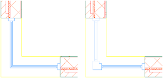
As you can see in the image above, you have the option of specifying butt glazing at the corner. If this toggle is unchecked, you will get a frame at the corner, and you can specify the exposed inside width of the frame (dimension "K"). Window Styles from previous releases will default to having the Butt Glazing at Corner toggle checked (K - Width of 0). The out-of-the-box "regular" Window Styles also have the Butt Glazing at Corner toggle checked. While there is no reason to create a separate Window Style with "Corner Butt Glazing" in the name, the out-of-the-box content includes a "Corner Butt Glazing - Picture" Window Style that is used by the Tool palette tool of the same name.
Corner Windows are placed using a new command, WINDOWCORNERADD. You can create your own Corner Window Tool palette tool by copying one of the out-of-the-box tools and modifying the properties to use your desired style. In addition to the out-of-the-box style-specific tools on the Corner Windows palette in the Design Tool Catalog (under Doors and Windows),

you can find a generic Corner Window tool in the Stock Tool Catalog, under Architectural Object Tools. You can also invoke the WINDOWCORNERADD command on the Home ribbon tab, on the Build panel, by clicking the down arrow icon at the right side of the Window split button and choosing the Corner Window tool.
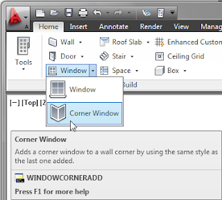
Corner Windows must be placed by selecting a Wall; they can not be inserted as free-standing objects, like "regular" Windows. The Wall selected must also be intersected by another Wall, and both must clean up to form an "L" corner; the angle need not be 90 degrees. "T" or "X" intersections will not work. Curved Walls are also not currently supported. If you try to place a Corner Window and nothing happens when you select a Wall, check the Command: line for helpful messages such as "No valid wall intersection found for selected wall." to help you figure out why the Corner Window is not being placed.

After selecting the first Wall, a preview of the Corner Window will appear on screen. If there are valid corners at each end, you can move your cursor closer to the desired end to have the preview appear at the correct end. When adding a Corner Window, you will find that instead of being able to edit the usual Width property (Dimension A, which is still there, but not editable), you now have two new properties, Width 1 (Dimension E) and Width 2 (Dimension F), which allow you to control the width of each leg of the Corner Window. Width 1 applies to the leg within the selected Wall, Width 2 applies to the other Wall. The Width property will display the sum of the Width 1 and Width2 values.
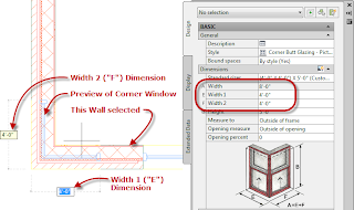
In the image above, the horizontal Wall was selected, and the dynamic dimension for Width 1 is initially active. You can set the widths using the dynamic dimensions or by editing the properties on the Design tab of the Properties palette. Use the Opening measure property to choose whether the specified Width 1 and Width 2 values are measured to the Outside of opening, Center of opening or Inside of opening.
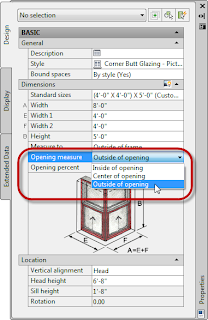
Standard Sizes remain the same as before - when placing a Corner Window, the width dimension specified is used for both legs.
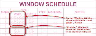
Corner Windows can be tagged and scheduled just like "regular" Windows". The Width automatic property source will show both widths, separated by " x ".
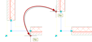
Corner Windows can be grip edited similar to "regular" Windows, with some Corner-Window-specific changes. The arrow-shaped Flip grip located at the jamb will swap the Width 1 and Width 2 legs. This does not just swap the width values, but actually moves the Width 1 leg to the other Wall, as if it had been selected first.
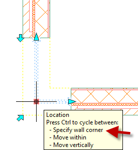
The square Location grip offers a different first option. Instead of "Move along" Wall, which makes no sense for a Corner Window, it offers "Specify wall corner", which allows you to move the Corner Window to any other valid "L" corner Wall intersection, even one involving two different Walls.
Cautions
Corner Windows should not be used in projects where any other team members are not on the 2012 release. While ACA 2012 uses the AutoCAD
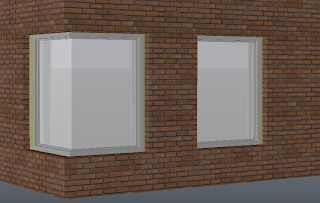
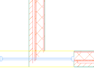
® 2010 file format and ACA 2010 and 2011 will be able to open the file, neither of those releases will support the proper display of Corner Windows and you will get a "regular" Window, with the width equal to the sum of the center of opening values of Width 1 and Width 2, anchored to the Width 1 Wall at the time it was saved in 2012 and hanging over the end of the Wall, as seen in the image below.
Schedules created in 2012 with Corner Windows will also show undesired results when opened in 2010 or 2011. (The Width column will show like a formula property with an error, displaying the entire formula used to calculate the Width value.) In limited testing, it appears that opening/editing/saving in 2011 and reopening in 2012 causes no harm, but you will want to test that in your own environment and with the sorts of edting you expect to do before relying on it being safe.
The openings created by Corner Windows are not taken into consideration when using the Offset or Center options when placing other opening objects (Doors, Windows, Openings, Door/Window Assemblies) in a Wall that has a Corner Window. This is not the behavior I expected, so you will want to keep that in mind.
Any type of Window Style can be used as a Corner Window, but it may not be appropriate for all types. For example, you can set up a butt-glazed Glider Peak Corner Window, but that does not mean you should (nor does it mean it could be built).

 You can also temporarily maximize the currently active viewport and then restore the previous viewport configuration using this first menu.


