August 28, 2009

Another Automatic Property Override Sample

For those of you who never tire of examples of using a manual property and a formula property to allow for overriding the value of either an automatic property or a style-based manual property on an object-by-object basis (and for those who have never seen an example of this), I have posted a ZIP file with a file created in AutoCAD® Architecture 2009 to the Default Finish Scheduling thread in the Autodesk AutoCAD Architecture Discussion Group. Look for the RoomFinishTest.zip file attached to my August 24, 2009 reply.

The sample file has a style-based Property Set with text-type manual properties for entering typical room finishes for a specific Space Style. If you set up separate Space Styles for each room type you have anyway, doing this provides an easy way to get schedulable finish information into your drawings, since you only need to enter the finish information once, in the Space Style, for each style. If your projects usually have the same finishes in all Spaces of the same type/style, the style-based Property Set could be all you would need. Even if you had two or three different sets of finishes for a particular Space type (for example, for offices), if there were a significant number of each office type, you would probably want to create a separate Space style for each office type, and assign the appropriate finishes at the style level.

Many projects will have individual Spaces that will have some variation from the typical finishes for its Space type. If there are only a few of these, it may not be too much trouble to create separate Space Styles for each variant. But if there are a large number of unique variants, creating a Space Style for each will quickly become a burden. Rather than give up on style-based properties and go to object-based properties (where you would need to enter the data for each individual Space), you can set up an object-based manual override property to hold a different value for just that one Space, and a formula property that you use in the Schedule Table, that checks to see if the override property is set to its default value. If so, the formula passes through the style-based typical value. If not, the formula passes throught the override value. That allows you to take advantage of the power of style-based properties without needing to create a separate Space Style for each variant.

The sample file has a handful of Space Styles and two custom Property Sets. The SpaceStyleFinishes Property Set contains five manual properties for entering the typical floor, base, wainscot, wall and ceiling finishes for a particular Space Style. Depending upon the nature of your work and the way you document finishes, you may need to add or subtract properties here; for example, you may want four wall finish properties (north, south, east and west). For the purposes of being able to create the example file without taking an inordinate amount of time, I limited the properties to those five. (As always, click on any image to see a full-size version; use the Back button on your browser to return here.)This Property Set applies to Space Styles and is attached to each style on the General tab, using the Property Sets... button.If you have a number of frequently used finishes, consider setting up a List Definition that applies to Manual Properties to hold the options for each finish type, then using that to speed entering values (and make them consistent). The sample file does not include this; values there were manually entered in the Edit Property Set Data dialog.The SpaceObjectFinishes Property Set contains two properties for each property in the style-based property: an Override property to hold the override value, when one is desired, and a formula property to pass through the appropriate value, as noted above.The default value for the override properties is "USEDEFAULT!" (without the quotation marks). The exact value you use is not important, so long as it is not anything that could be a value you would want to use for the override. The formula property for each finish type is similar to that shown below for the FloorFinish formula property.
If "[FloorOverride]" = "USEDEFAULT!" Then
RESULT = "[SpaceStyleFinishes:FloorDefault]"
Else
RESULT = "[FloorOverride]"
End If
The formula tests the override property to see if its value remains the default value. If so, it passes through the typical, style-based value. If not, it passes through the override value. By using this property in your Schedule Table Style and/or Schedule Tag, you get the advantages of both style- and object-based properties.

The sample file also contains two Schedule Table Styles. One is meant for final documents, and shows only the "final" formula property value for each Space.You can not use the Cell Edit feature to edit the finish values in this Schedule Table, however, because automatic properties like formula properties can not be edited that way. If you prefer to make post-placement edits by using Cell Edit, then you will also want to have a "working" Schedule Table Style, which is the second one in the sample file. This lists the formula property, style-based typical property and object-based override property for each finish type. You can use Cell Edit on either the typical property, changing the formula property value for all instances of that style that do not have overrides, or the override property, changing the formula property value for just that Space.In the partial Schedule Table shown above, you can see that an override value has been entered for the floor finish for the last three Office Spaces (111, 112 and 113), changing the default value of CPT 2 to CPT 5.

August 23, 2009

AutoCAD® Architecture 2010 – UI Changes, Part 6 – The Ribbon, Render Tab

Render Tab
The Render tab is the fourth static (always available) tab provided in the out-of-the-box ACA CUI. The image below and all screen captures in this article are based on the shipping version.
Tools Panel
The Tools Panel contains a single button that toggles the tool palettes on and off, setting the Visualization tool palette group current when toggling it back on.If you would prefer that it simply switch to the Visualization tool palette group, refer to this previous article for instructions on how to modify the CUIX file.

Render Panel
The Render Panel contains commands related to rendering.The Render split button split button allows you to render or render a region.The main button will change to run the most recently chosen option from the drop-down list. The Render Presets drop-down button offers a list of named, pre-established rendering settings. The most recently used choice is displayed when the drop-down list is collapsed.Choose Manage Render Presets at the bottom of the drop-down list to open the Render Presets Manager dialog, where you can edit the current settings, review the settings assigned to any of the standard presets as well as create or edit custom render presets (RENDERPRESETS command). The button below the Render Presets drop-down does not execute a command, but shows a histogram indicating the progress of a rendering in progress. Selecting the button at the left side of the third row on the main panel, Render Output File, toggles whether or not a rendered image is saved to a file. When enabled (bluish background, rather than gray), the Browse for File button at the right side of that same row (elipsis icon) becomes enabled, allowing you to specify the path and file name for the rendering file. The text box in the middle of the third row will display the path and name of the specified file. Select the Render panel title bar to expand the panel. A slider button shows the current render quality. The Render Output Size drop-down offers four standard image sizes; choose Specify Image Size at the bottom to open the Output Size dialog, where you can set a custom size for the rendered image.The Adjust Exposure button (RENDEREXPOSURE command) opens the Adjust Rendered Exposure dialog when the LIGHTINGUNITS system variable is not set to 0. The Environment button opens the Render Environment dialog, where you can enable or disable "Fog" and control various parameters thereof (RENDERENVIRONMENT). The Render Window button (RENDERWIN) opens the Render window without starting a rendering operation, allowing you to view previously rendered images for drawings with a "render history." The open arrow pointing to the lower right icon, at the far right side of the Render panel title bar, will toggle the Advanced Render Settings palette on and off.

Materials Panel
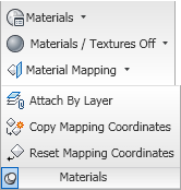
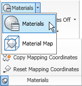
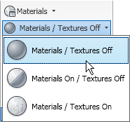
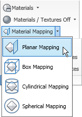
The Materials Panel contains commands related to render materials.The Materials split button allows you to toggle the open/close state of the Materials palette (MATERIALS command) or to set the mapping of materials on selected object(s) (MATERIALMAP).The command most recently selected from the drop-down will become the default for the button. The Materials/Textures drop-down list offers a choice of one of three states: both materials and textures off, materials on but textures off or both materials and textures on (VSMATERIALMODE).The button displays the current choice. The Material Mapping split button offers another way to use the MATERIALMAP command, this time with a preselected mapping type: Planar, Box, Cylindrical or Spherical.The main button appears to be fixed on "Planar". Selecting the Materials title bar will expand the panel to reveal three additional commands: Attach By Layer (assign materials by the object's layer - MATERIALATTACH), Copy Mapping Coordinates (copy material mapping from one object to another - MATERIALMAP, copY mapping to option) and Reset Mapping Coordinates (reset the mapping to the map defaults - MATERIALMAP, Reset mapping option).

Sun & Location Panel
The Sun & Location Panel contains commands related to including a sun-like light source in your renderings.The Sun Status command button allows you to toggle the sun on and off (SUNSTATUS system variable). The Sky button presents itself as a split button, but I was not able to find a way to make this button active. It will display the value of the SKYSTATUS systen variable, which allows you to set whether or not the sky illumination is computed at render time. Changing the value of SKYSTATUS changed the text shown with the button, displaying the current status. It may be that this only becomes active at an appropriate point in the rendering process, which is not something I do on a regular basis. The Set Location button allows you to specify the geographic location of the objects being rendered, so that the sun angles are set correctly. The Date and Time sliders become active when the sun is turned on, and allow you to specify the date and time of the rendering, and the sun angles will be set accordingly. The arrow icon at the far right side of the Sun & Location panel title bar toggles the Sun Properties palette, where you can make addtional sun parameter settings.

Lights Panel
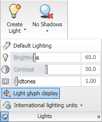
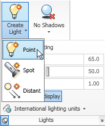
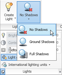
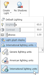
The Lights Panel contains commands related to lighting.The Create Light split button allows you to place one of three types of lights: Point (POINTLIGHT), Spot (SPOTLIGHT) or Distant (DISTANTLIGHT).The last type chosen from the drop-down list becomes the command executed by the button; the "Create Light" text remains constant. The Shadows drop-down button allows you to set the type of shadows: none, ground or full (VSSHADOWS command).The last option chosen is displayed on the button. Select the Lights panel title bar to expand the panel. The first button on the expanded panel is the Default Lighting button (DEFAULTLIGHTING), which toggles between the default lighting and the lighting placed. The button is highlighted when Default Lighting is active. Three slider controls follow, giving control over Brightness, Contrast and Midtones (RENDEREXPOSURE). The Light glyph display button toggles the display of light glyphs in the drawing (LIGHTGLYPHDISPLAY). This button is also highlighted when active, in this case when the display of light glyphs is enabled. The lighting units drop-down allows you to choose from Generic, American and International lighting units.Generic lighting has no units and "standard" lighting. The other two use the units indicated and photometric lighting.

Camera Panel
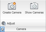
The Camera Panel contains commands related to cameras.The Create Camera command button runs the CAMERA command, creating a camera object. The Show Cameras command button allows you to toggle the visibility of camera glyphs in the drawing file (CAMERADISPLAY). The button is highlighted when cameras are shown. Select the Camera panel title bar to expand the panel and reveal an additional button, Adjust, which allows you to change the view of a selected camera (AECCAMERAADJUST).

Animations Panel
The Animations Panel contains commands and controls related to animations.The Animation Motion Path command button allows you to set camera and/or target paths and make other animation settings in the Motion Path Animation dialog (ANIPATH command). There are four annimation control buttons: play, pause, record and save. The Walk/Fly split button gives you access to the Walk (3DWALK) and Fly (3DFLY) command buttons as well as the Walk and Fly Settings (WALKFLYSETTINGS).The last item selected becomes the command on the button.

August 17, 2009

AutoCAD® Architecture 2010 – UI Changes, Part 5 – The Ribbon, Annotate Tab

Annotate Tab
The Annotate tab is the third static (always available) tab provided in the out-of-the-box ACA.cuix. The image below and all screen captures in this article are based on the shipping version.
Tools Panel
The Tools Panel contains a single button that toggles the tool palettes on and off, setting the Document tool palette group current when toggling it back on.If you would prefer that it simply switch to the Document tool palette group, refer to this previous article for instructions on how to modify the CUIX file.

Text Panel
The Text Panel contains commands related to the creation and editing of text.The Text command button starts the MTEXT command. The Check Spelling command button allows you to run the SPELL command to check the spelling of words in the drawing. The Text Style drop-down button displays the name of the current text style and allows you to set any other text style defined in the drawing current.Select Manage Text Styles... at the bottom of the drop-down to open the Text Style dialog if you need to create a new text style. The Find text button offers an edit box on the left where you can enter the text string for which you want to search/replace and a button on the right that opens the Find and Replace dialog. The previously used Find string will be displayed in the text box after searching or replacing is complete. The final button on the main panel is the Annotation Text Height drop-down, which displays the current default text height, as stored in the TEXTSIZE variable. When you first start up ACA, there is only one value in the list. As you use the TEXTSIZE variable to change the default text height or as you open/start additional drawings that have a different default text height set, the additional values will appear on the list. Note that changing the height of existing MTEXT (on the MTEXT editor bar or on the Properties palette) does not add items to the list.

Selecting the Text title bar will expand the panel to reveal four additional commands. The Scale button runs the SCALETEXT command, which allows you to rescale selected text objects without changing their individual locations. The Justify button changes the justification point of text, using the JUSTIFYTEXT command. The Field button runs the FIELD command. The Update Fields button allows you to manually update field values with the UPDATEFIELD command.

Dimensions Panel
The Dimensions Panel contains commands related to dimensioning (AEC and AutoCAD).The AEC Dimension split button allows you to choose one of three AEC Dimension ribbon tools, each offering a different AEC Dimension style (AEC Dimension Interior, AEC Dimension Exterior and AEC Dimension Exterior R.O.).Note that for this split button, the command that the top half of the button will run directly will change to the last item chosen on the drop-down list. If you have custom AEC Dimension styles for which you have (or can make) tool palette tools, you could customize the ACA.cuix file and add your styles to the list. The top row of the main Dimensions panels features a series of buttons that allow various types of AutoCAD Dimensions to be placed. These should be familiar to anyone who used the old Dimension toolbar in previous releases. Starting from the left, you have the Dimension, Linear button (DIMLINEAR command); a split button with the Continue (DIMCONTINUE, always available on the left part) and Baseline (DIMBASELINE) on the drop-down;the Dimension, Aligned button (DIMALIGNED); the Dimension, Angular button (DIMANGULAR); a split button with Radius (DIMRADIUS) and Diameter (DIMDIAMETER) on the drop-down (Radius is initially featured on the left part, but this split button will change to the last one used);and, at the right end, the Dimension, Center Mark button (DIMCENTER). The second row on the main panel has a single button, AEC Dimension Style, that will open the Style Manager, filtered for AEC Dimension Styles (AECDIMSTYLE). At the left of the third row is the Dimension Style button (DIMSTYLE), which opens the Dimension Style Manager dialog for creating and editing AutoCAD Dimension Styles. The balance of the third row features the Dimension Style drop-down button, which displays the name of the current AutoCAD Dimension Style, and allows you to set a different one current by selecting it from the drop-down list. Selecting the Dimensions panel title bar will expand the panel and reveal four additional dimension-related commands: Dimension Spacing (DIMSPACE), Ordinate (DIMORDINATE), Tolerance (TOLERANCE) and Arc Length (DIMARC).

Scheduling Panel
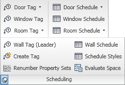
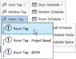
The Scheduling Panel contains commands related to the ACA Schedule feature.All of the commands in this panel that add a specific Tag or Schedule Table are ribbon tools. At the top of the first column, the Door Tag drop-down button allows you to use either of the out-of-the-box Door Tags, non-project-based or project-based.The Window Tag button adds the out-of-the-box Window tag. The Room Tag drop-down button offers a choice of three tags for Spaces: the non-project-based Room Tag, the Room Tag - Project Based and the Room Tag - BOMA.The second column features tools that allow you to add a Schedule Table to your drawing. The Door Schedule drop-down button offers the non-project-based and project-based Door Schedules The Window Schedule button allows you to add a Window Schedule, and, with the Room Schedule drop-down button, you can add the out-of-the-box Room Schedule, Space Schedule - BOMA or Space Inventory Schedule.Selecting the Scheduling title panel expands the panel, revealing tools to add Wall Tags and Schedules, as well as the Create Tag (DEFINETAG - opens the Define Schedule Tag "wizard" dialog), Renumber Property Sets (PROPERTYRENUMBERDATA - opens the Data Renumber dialog) and Schedule Styles (SCHEDULESTYLE - opens Style Manager, filtered for Schedule Table Styles). The Evaluate Space tool runs the AECSPACEEVALUATION command, which opens the Space Evaluation dialog.

Callouts Panel
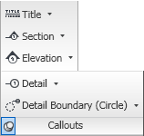
The Callouts Panel contains commands related to adding callouts.All of the buttons on this panel are split buttons and all of the tools therein are ribbon tools, allowing you to add out-of-the-box callouts without using the Properties palette directly. See the image below for the various callouts available for each type.
The most recently used command in each drop-down list becomes the featured command on the button.

Keynoting Panel
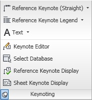
The Keynoting Panel contains commands related to adding keynotes and "other notes".The three buttons on the main panel are all split buttons and all of the tools therein are ribbon tools, allowing you to add keynotes, keynote legends and text/leadered text/leadered symbols (the "other notes") without using the Properties palette directly. The options are shown in the image below; the most recently used command on each drop-down will become the featured command on the button.Commands on the expanded panel (select the Keynoting title bar) allow you to open up the Keynote Editor (LAUNCHKEYNOTEEDITOR command), select a database to be added to the list of available keynote databases (Select Database - KEYNOTEDATABASERESELECT) and toggle the display of either Reference or Sheet keynotes (Reference Keynote Display - REFERENCEKEYNOTETOGGLE / Sheet Keynote Display - SHEETKEYNOTETOGGLE).

Markup Panel
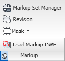
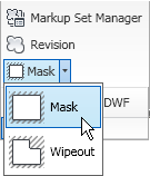
The Markup Panel contains commands related to drawing revisions.The Markup Set Manager command button (MARKUP command) opens the Markup Set Manager palette, allowing you to manage the DWF markups in the drawing. Draw layer-keyed revision clouds with the Revision command button (ANNOREVISIONCLOUDADD). The Mask split button allows you to add Mask Blocks or Wipeouts.The button portion always displays the Mask command. One additional command is available on the expanded panel (select the Markup title bar), Load Markup DWF (OPENDWFMARKUP), which allows you to load a DWF file which contains markups into your drawing.

Annotation Scaling Panel
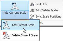
The Annotation Scaling Panel contains commands related to annotation scaling.The Currnent Scale split button allows you to add or delete the current scale from selected annotative objects. The most recently selected option becomes the button command.The Scale List command button (SCALELISTEDIT command) opens the Edit Scale List dialog, which allows you to add to, edit, delete from and rearrange the order of the listed pre-defined drawing scales. The Add/Delete Scales command button allows you to add or remove drawing scales from selected annotative objects (OBJECTSCALE). You can align all scale representations of an annotative object (should any individual representations have been grip edited) with the current scale representation (not the original "insertion" point) by using the Sync Scale Positions command button (ANNORESET).

August 13, 2009

Content Browser i-drop Hotfix Released (Sort Of)

While the Hotfix has not shown up on the official AutoCAD® Architecture Updates & Service Packs page, apparently is has been sent to at least one person who submitted a support claim related to the fact that installing ACA 2010 breaks the ability to directly i-drop a tool from Content Browser into the Workspace in previous releases. Fortunately, that person was Odin Cary, who has posted the files to his ARCHIdigm website, as I learned in this thread in the Autodesk Discussion Groups. Thanks to Odin for making the files available, and thanks to Pedro Aroso for spreading the word.

If you have installed 2010 but still need to run earlier versions to complete projects already underway (as you are permitted to do if you are on subscription) and the breaking of direct i-drop is cramping your style, you may want to get the files from Odin's site, rather than waiting for the link to show up on the Autodesk site.

August 06, 2009

Live On-Line Training

Speaking of Paul Aubin, he is now offering live, on-line training sessions. If you are wondering how to get the most bang for what remains of your recession-reduced training budget, you may want to keep an eye on the classes he is offering. So far, these have all been Revit classes, but he has requested input on future topics for both Revit and AutoCAD Architecture. You can pay for one connection and, if you have a projector or a conference room with a large monitor, as many people as you can get in the room (respecting building code occupancy limitations, of course) can watch the session. The initial presentation of each session is live, using GoToMeeting software, and includes the potential for two-way VOIP communication (plus a Chat feature, if, like me, your computer does not have a microphone hooked up to it). There is an option to call in, if you prefer, as well. The software also allows Paul to post occasional polls (and even a quiz on the previous session). The sessions are recorded, and are posted a few days later for review or to allow later watching of the session should you not be able to attend the live event.

The current class is a five-session series on the Revit family editor. As a "late" registrant, I watched the recorded version of the first session, and attended the live presentation of the second session today. The image below shows a screen capture from today's presentation, in mid-demonstration in Revit, to give you a feel for the look of the presentation. (Click on the image to see a full-size version; use the Back button on your browser to return here.)As a relative newbie with Revit (having just finished three days of "essentials" training last week), I found both to be quite informative, and look forward to the remaining three classes in this series. Paul provides a nicely illustrated PDF that includes tutorials covering the examples he shows during the class along with explanatory material. There is also a ZIP file containing a dataset with files related to the tutorials.

If the Revit family editor is something that you have always wanted to know more about, or if you have some experience with it but are interested in how it is done in the 2010 interface, then you may want to consider signing up for this class, even though two sessions have already been presented. You can watch the recorded version of the first two classes and then catch the live presentation of the following three classes, starting next Thursday (August 13, 2009). Having done a session each way, I can say that other than the polling and the opportunity to ask a question at the end of the live session, there is no substantive difference between the two. (I assume that the polls and parts where Paul asked for a show of hands were edited out of the recorded version.) The fifteen-registrant limit mentioned in Paul's blog article has been increased to 200, so there is plenty of room if you are interested.

Full Disclosure: I have known Paul through the Autodesk Discussion Groups, have met him and attended his classes at AU over the years and recently helped him update his Mastering AutoCAD Architecture book for the 2010 release. Paul provided me with a complementary registration for the Family Editor class.

Mastering AutoCAD Architecture 2010


I had previously indicated that I would explain the relative dearth of new posts in the last few months, and now that Paul Aubin has made it public knowledge, I am happy to inform anyone not already aware that there will be an update of his Mastering AutoCAD® Architecture for the 2010 release.

Over the last two-and-one-half months or so, I have had the privilege and pleasure of helping Paul with the rather substantial task of updating the tutorials in the book to both make use of new features added since 2008, when appropriate, and coordinate with the ribbon interface. That required a large number of the figures in the book to be recaptured to show the current interface.

You can find more information on the new book on Paul's website, and, if you are so inclined, use the link there to pre-order the book from amazon.com.

Now that my contribution to that effort is over, I hope to have time to get back to posting here and pick back up on my ACA UI Changes series.

August 04, 2009

eTransmit Setups Issue

I am not well-versed in either the Drawing Management system or eTransmit, but in exploring the use of eTransmit with a Project Navigator project, I found a minor issue that I think is a bug. It could be "as designed," but I would not have designed it that way, so I will consider it a bug until enlightened otherwise. Fortunately, there is a workaround.

In Project Navigator, on the Sheet Sets tab with the Sheet Set View current, if you right-click on the Sheet Set node, the context menu includes an eTransmit Setups option.Select that option, and then either create a new setup or modify an existing setup. In the Modify Transmittal Setup dialog, in the lower-right corner, both the Include project information and the Include project default templates options are disabled. The latter should be, until the former is selected, but the former should not be disabled, in my opinion. I could find no combination of other settings in this dialog that would activate the Include project information toggle.
That same context menu, as well as the context menu that comes up when right clicking on a drawing file or folder on the Sheets, has an eTransmit option. Selecting that opens the Create Transmittal dialog, which features a Transmittal Setups button that initiates the same sequence of dialogs as the eTransmit Setups option on the context menu.When you get to the Modify Transmittal Setup dialog through this avenue, the Include project information toggle is active, and checking it activates the Include project default templates toggle, allowing you to make these settings and save them to a Transmittal Setup for later use.

Note that if you save the setup with one or both of the "project" toggles checked, and later reopen it by using the eTransmit Setups option on the Sheet Set node right-click context menu and modifying the saved setup, those options will be disabled (and no check marks will appear). That should not be a cause for alarm; in my somewhat limited testing so far, even if I made a change elsewhere in the dialog and resaved the setup, the check mark(s) were preserved when opening it through the eTransmit/Create Transmittal dialog method.

My guess is that there are times when the Include project information toggle should not be active (when accessed outside of Project Navigator, via AutoCAD Sheet Sets), that the dialog definition has it disabled by default, and enabling it when using the eTransmit Setups option got missed (or accidentally removed).