Display By Layer
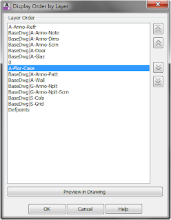
The Display Order panel features one tool, Display By Layer, which runs the AecLayerOrder command.

This tool allows you to rank the layers in a drawing and then have the display order set by the order in which the layers are ranked. This is a one-time deal. Future objects will appear on top of all previous objects; after setting the draw order by layer, that order is not dynamically applied to future objects. You can, of course, re-run the command, and the list is "remembered" with the drawing, so you do not need to recreate the list after saving, closing and then reopening the file. Note also that there is no way to "automatically clear" the draw order and return to what it was prior to applying this command. Two less-than-obvious ways this feature works involve external references. While you can re-order the layers of an external reference in the list and have it affect the display order, there are two limitations:
- Even though you can intermingle layers from an external reference with those of the host drawing and those of other external references, the net effect is to re-order the display of objects within the external reference relative to one another. All of the objects within a given external reference then are drawn relative to other objects based on the layer on which the external reference is inserted. For example, in the dialog above, even though the host layer A -Flor-Case appears in the list above the externally referenced layer BaseDwg|A-Wall, because the BaseDwg external reference is inserted on layer A-Anno-Refr (at the top of the list), all objects in the BaseDwg external reference will appear above objects on A-Flor-Case (or any other host drawing layer other than A-Anno-Refr).
- After saving a file with external references to which Display By Layer has been applied and then closing it, when you re-open the file, the display order applied to the layers in the externally referenced files is not automatically applied. The Layer Order list is remembered, however, so you can re-run the command to get the externally referenced layers order back to the way it was prior to saving/closing the file.
Escarpment

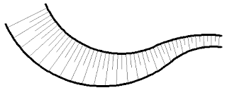
Use the Escarpment tool (AecEscarpment command) on the Graphics panel to create the linework often used to depict a sloping condition quickly and easily. You only need to pick the upper and lower sides and provide a distance between lines on the upper side. The generated linework is placed as a Block Reference, on the current layer; nested objects are on the current layer with ByBlock color, linetype, plotstyle (for drawings using named plot styles) and lineweight and ByLayer transparency and material.
To Layer 0
The To Layer 0 tool (AecMoveBlockToLayer0 command) on the Block Definition panel moves all nested objects within the Block Definition of a selected Block Reference to Layer 0. Unlike the Set Nested Objects to ByBlock option on the right-click menu when a block reference is selected (SetNestedObjectsByBlock command), this tool only changes the layer of the nested objects and leaves other attributes (color, linetype, plot style, and lineweight) alone. The SetNestedObjectsByBlock command also changes the color, linetype, plot style, and lineweight of the nested objects to ByBlock. The To Layer 0 tool also works on nested blocks, setting the objects within them to layer 0 as well; the SetNestedObjectsByBlock command does not affect objects within nested blocks.
Change Block
This tool runs the AecChangeBlock command, which allows you to select one or more Block References (which can have different Block Definitions) in the drawing and specify another Block Definition in the drawing for them. Insertion point, scale factors, layer, color, etc. remain unchanged. You have to type in the name of the new Block Definition. The command does offer a "?" option, which will list all of the Block Definitions in the drawing on the command line, for your reference.
No comments:
Post a Comment