The View tab is the fifth static (always available) tab provided in the out-of-the-box ACA CUI. The image below and all screen captures in this article are based on the shipping version.

Navigate Panel
The Navigate Panel contains commands related to navigating within a drawing.
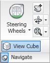 The Steering Wheels split button allows you to activate the Steering Wheel and choose the desired type.
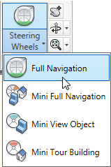 The drop-down list offers a choice between the Full Navigation Steering Wheel and three “mini” steering wheels; the main button initially defaults to Full Navigation, but will change to the most recently selected item from the list. The Pan Realtime command button executes the PAN command. The Orbit split button allows you to initiate one of three orbit types.
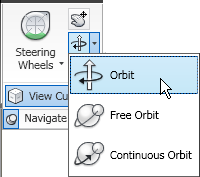 The drop-down includes the Orbit (3DORBIT), Free Orbit (3DFORBIT) and Continuous Orbit (3DCORBIT) commands. The last one chosen becomes the one activated by the main command button. The Zoom split button allows you to perform various ZOOM command options.
 These are the same options available from the Zoom split button on the View panel (floating/Home tab), with the exception of omitting the Pan Realtime button, which is available separately on the Navigate panel. Click on the Navigate panel title bar to expand the panel and reveal the View Cube command button. This will only be active when your visual style is set to something other than 2D Wireframe; when active, it toggles the display of the View Cube on and off in all locations (main drawing window as well as other windows, such as the Object Viewer).
Appearance Panel
The Appearance Panel contains commands related to the drawing view and the appearance of objects.
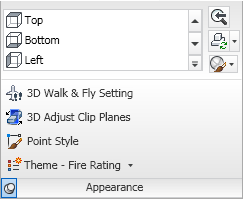 The View drop-down button displays a list of defined Views in the current drawing and allows you to restore one by selecting it.
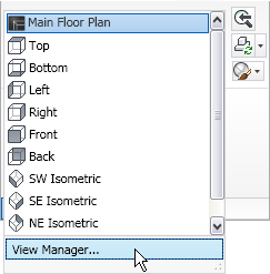 Use the up and down arrows at the right to scroll the list or use the drop-down button at the bottom right to see the defined Views in a drop-down list and expose the View Manager button, which opens the View Manager dialog (VIEW command). The Previous View command button runs the Previous option of the VIEW command. The Regenerate split button offers a choice of three regeneration-related commands: Regenerate Drawing (REGEN command), Regenerate Drawing and Viewports (REGENALL command) and AutoCAD-Architecture-specific Regenerate Model (OBJRELUPDATE command).
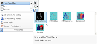
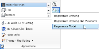 The main button always runs the Regenerate Drawing (REGEN) command. The Visual Styles drop-down button allows you to choose one of the currently defined visual styles in the drawing from an icon list (choice runs VSCURRENT command), save the current visual display as a named style (VSSAVE command) – provided that 2D Wireframe is not the current setting or open the Visual Styles Manager palette (VISUALSTYLES command).
 Expanding the panel by selecting the Appearance title bar provides access to four additional buttons. The 3D Walk & Fly Settings button opens the Walk and Fly Settings dialog (WALKFLYSETTINGS). The 3D Adjust Clip Planes button (3DCLIP) opens the Adjust Clippling Planes dialog. The Point Style button opens the Point Style dialog (DDPTYPE), allowing you to specify how Point objects appear on the screen. The Theme – Fire Rating drop-down button allows you to activate one of seven out-of-the-box Display Themes (DISPLAYTHEMEADD command).
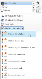 Each of the buttons on the drop-down runs a ribbon tool.
Coordinates Panel
The Coordinates Panel contains commands related to the User Coordinate System (UCS) and the UCS Icon.
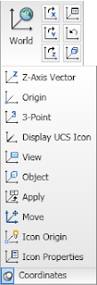 The World command button sets the UCS to “World,” aligning it with the World Coordinate System (WCS) (UCS command, World option). The X, Y and Z command buttons (left buttons on top, middle and bottom rows of the main panel) allow you to rotate the current UCS about the X-, Y- and Z-axes, respectively (UCS command; X, Y and Z options). The Named command button (top row, right button) opens the UCS dialog to the Named UCSs tab, allowing you to manage the defined user coordinate systems in the current drawing (UCSMAN). The Previous command button (middle row, right button) restores the previously current UCS for the current space (model or paper) – the last 10 in each space are retained (UCS command, Previous option). The Face command button aligns the UCS to a selected face on a 3D Solid (ALIGNUCSTOFACE). Selecting the Coordinates title bar expands the panel to reveal ten additional command buttons. The Z-Axis Vector command button moves the UCS origin to the first point selected and then rotates the UCS to have the Z-axis pass through the second point selected (UCS command, ZAxis option). The Origin command button moves the UCS origin point to a specified point (UCS command, Origin option). The 3-Point command button allows the user to establish a UCS by specifying an origin point, a point on the positive X-axis and a point on the positive Y-axis. (UCS command, 3point option). The Display UCS Icon command button toggles the visibility of the UCS icon in the current viewport (UCSICON command, ON and OFF options). The Apply command button applies the current UCS to a selected viewport (UCS command, Apply option). The Move command button moves a defined UCS (UCS command, Move option). The difference between the Origin and Move options is that Origin creates a new UCS with the specified origin point while Move redefines the current UCS, possibly affecting other viewports (unless the WCS is current, in which case Move also creates a new, unnamed UCS). The Icon Origin command button toggles between the two possible locations for the display of the UCS Icon – at the UCS Origin, if the current view permits, or always in the lower-left corner, even if the current view would permit (UCSICON command, Noorigin and Origin options). The Icon Properties command button opens the UCS Icon dialog, which allows you to control the appearance of the UCS Icon, including style, size and color.
Viewports Panel
The Viewports Panel contains commands related to both tiled (Model tab) and floating (Layout tab) viewports.
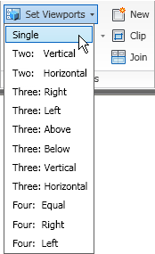
 The Set Viewports drop-down button, only active when the Model tab is active, allows you to choose from a list of pre-defined tiled viewport configurations (VPORTS command).
 The Create Viewport split button, only active when a Layout tab is active, has two command buttons on the drop-down list: Create Polygonal, allowing you to draw a polygonal viewport by selecting vertex points (-VPORTS command, Polygonal option) and Create from Object, which allows you to select a closed polyline or a circle and create a viewport in that shape (-VPORTS command, Object option).
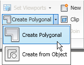 The last button selected on the drop-down list becomes the command executed by the main button. The Named command button opens the Viewports dialog to the Named tab, where saved viewport configurations can be selected (VPORTS). The New command button opens the Viewports dialog to the New Viewports tab and allows you to create a new named viewport configuration, or edit existing ones (VPORTS). The Clip command button, which can only be used in a Layout tab (TileMode 0), runs the VPCLIP command, which allows you to clip an existing floating viewport, either using an existing closed object (polyline or circle) as the clipping boundary or allowing you to draw a polygonal boundary on the fly. The Join command button, only active when the Model tab is current, allows you to join two adjacent tiled viewports, provided that the end result is a rectangle (-VPORTS command, Join option).
Face Effects Panel
The Face Effects Panel contains commands related to the way faces of 3D objects display.
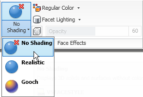
 The VSFaceStyle split button allows you to choose type of shading used on the faces, no shading, realistic or gooch.
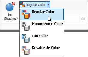
 The Color split button allows you to set a new value for VSColorMode: 0 (regular), 1 (monochrome), 2 (tint) or 3 (desaturate).
 The Lighting split button allows you to set a value for VSLightingQuality: 0 (facet), 1 (smooth) or 2 (smoothest).
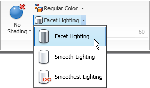 The main command button will change to the last option selected from the drop-down for all three of these split buttons. The X-Ray Effect command button toggles the sign of the value of VSFaceOpacity, turning the x-ray effect on and off. When it is on, the Opacity slider control allows you to change the level of transparency, from 0 to 100. On my computer, both 0 shows with full opacity, 1 is the most transparent and 100 is full opacity. For this to be effective, the current visual style needs to be a type that hides and face shading must be turned on.
Edge Effects Panel
The Edge Effects Panel contains commands related to the way edges of 3D objects display.
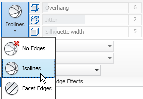
 The VSEdges drop-down button allows you to select an edge display type: No Edges, Isolines or Facet Edges (VSEDGES). Supported edge types varies between the available visual style types.
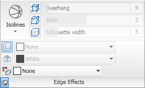
 The Edge Overhang command button toggles on and off the effect that extends the edge lines of 3D solids and Mass Elements beyond the end of the edge (VSEDGEOVERHANG). The adjacent slider control allows you to control the amount of the overhang (VSEDGEOVERHANG). The Edge Jitter command button toggles on and off the effect that makes the edges of 3D Solids and Mass Elements “wavy” (VSEDGEJITTER). The adjacent slider control allows you to control the degree of waviness. The Silhouette Edges command button toggles on and off the display of a silhouette around the outer edges of 3D Solids and Mass Elements (VSSILHEDGES). The adjacent slider control allows you to control the width of the silhouette. Selecting the Edge Effects title bar expands the panel to reveal two toggles and three drop-down lists command buttons. When VSEdges is set to Facet Edges, the Obscurred Edges (VSOBSCUREDEDGES) and Intersection Edges (VSINTERSECTIONEDGES) become active, allowing you to toggle the display of obscurred (hidden) edges and the edges at the intersection of two 3D Solids or Mass Elements. When toggled on, the adjacent drop-down list becomes active, allowing you to set the color of obscured edges (VSOBSCUREDCOLOR) or intersection edges (VSINTERSECTIONCOLOR). The bottom drop-down allows you to set the color of visible edges of 3D Solids or Mass Elements (VSEDGECOLOR).
Windows Panel
The Windows Panel contains commands related to drawing and other interface windows.
 The Switch Windows drop-down button allows you to make any of the currently open drawings active, by selecting it from a list.
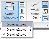 The Tile Horizontally, Tile Vertically and Cascade command buttons allow you to control the display of the currently open drawing windows (SYSWINDOWS). The Status Bar Options drop-down list allows you to control the display of icons and notifications on the Application Status Bar.
 The Drawing Status Bar command button toggles the display of the Drawing Window Status Bar (STATUSBAR). The Text Window command button toggles the display of the AutoCAD Text Window (TXTSCR). The Command Line command button toggles the display of the Command Line Window (COMMANDLINE). Clicking on the arrow icon at the far right of the Windows title bar executes the OPTIONS command, opening the Options dialog to the Display tab.
3 comments:
Hi David
Can you do me a favour and add a search engine for your site. You have lots of useful information but it's hard to find. It's a gadget under your layout page!
Thanks in anticipation :-)
Nathan
Well, it might be a gadget on my layout page if I had a layout page. I am still using an old template, and have not yet found the time to change over to the new system. I have some projects going on for the next few months that will likely tie up my free time, but perhaps when that is over I will make a stab at modernizing my blog.
There is a search box in the upper left corner when I visit the blog - or is that not as powerful as the gadget you mention?
As promised, it took a few months, but I did finally get around to updating the blog template and there is now a search gadget in the upper right side.
Post a Comment