May 19, 2009

AutoCAD® Architecture 2010 – UI Changes, Part 4 – The Ribbon, Insert Tab

Insert Tab
The Insert tab is the second static (always available) tab provided in the out-of-the-box ACA CUI. The image below and all screen captures in this article are based on the final beta version; it is possible that there could be some changes in the shipping version.
Reference Panel
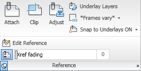
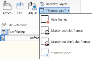
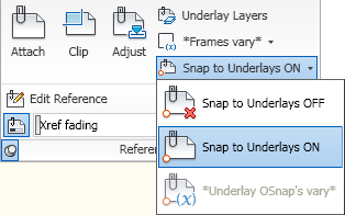
The Reference Panel contains commands related to reference files.The Attach command button allows you to use the Attach command to add an external reference (DWG), image, DWF, DWFx, PDF or DGN to your drawing file. The Clip command button allows you to clip an external reference, image, underlay (DWF, DWFx, PDF or DGN) or a viewport to a user-specified boundary. The Adjust command button allows you to adjust the fade, contrast, brightness and monochrome settings for images and underlays (DWF, DWFx, PDF or DGN). The Underlay Layers command button opens the Underlay Layers dialog, where you can control the visibility of individual layers in an underlay. The Frames command button allows you to choose how image and underlay frames will be seen (and plot).Frames can be hidden, displayed and plotted or displayed but not plotted. Setting a Frame setting will overwrite the current values of the IMAGEFRAME, DWFFRAME, PDFFRAME, DGNFRAME and XCLIPFRAME system variables. You can not directly choose the “Frames Vary” option; but changing any of the individual frame variables to something different will reset FRAME to 3 and activate the Frames Vary setting. The Underlays Snap command button allows you to control the ability to snap to geometry in underlays (DWF, DWFx, PDF or DGN).It toggles the value of the UOSNAP system variable, which, similar to the FRAME system variable, will overwrite the settings in the DWFOSNAP, PDFOSNAP and DGNOSNAP system variables, making them all either On or Off. You can not directly choose the “Underlay Osnap’s vary” option, but by setting one of the individual variables to a different value will reset UOSNAP to 2 and activate the vary option. The Edit Reference command button (first row in the flyout) runs the REFEDIT command. The Xref Fading command buttons (bottom row in the flyout) allow you to set the amount of fading, using either the slider or the edit box at the right, as well as toggle fading on and off, using the button at the left. (Note: You will not see any apparent change if you use the button at the left if the fading amount is set to 0, since there is no fading to toggle off.) Also note the arrow pointing down and to the right at the right side of the Reference panel title. Selecting that will open the External References palette.
Block Panel
The Block Panel contains command buttons for Multi-View Block and AutoCAD block related commands.The Multi-View Block command button runs the MVBlockAdd command; you will need to have at least one Multi-View Block Definition in the current drawing for this to be useful. The Insert Block command button opens the Insert dialog, allowing you to select a block definition in the drawing file or browse to an external drawing file to be inserted as a block. The Create Block command button opens the Block Definition dialog, allowing you to create a new block definition from objects in the drawing. The Edit Block command button allows you to choose a block definition in the current drawing and starts up the Bedit command for that definition. The Block Authoring palettes will open, and the Block Editor contextual tab will appear. The Set Base Point command button runs the Base command, which allows you to specify a point in the current file to act as the insertion base point when the current file is inserted into another file.

Attributes Panel
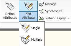
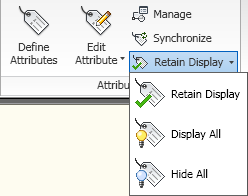
The Attributes Panel contains command buttons related to the creation, editing and display of Attribute Definitions/Attributes.The Define Attributes command button runs the Attdef command, allowing you to create attribute definitions for inclusion in a block definition. The Edit Attribute flyout offers two options for editing attribute values. Single runs the EAttEdit command, allowing you to edit the values, text options and properties of the attributes in a single instance of an attributed block. Multiple runs the -AttEdit command, which allows for the editing of attribute values individually or globally.The Manage command button opens the Block Attribute Manager (BattMan command), which allows you to edit the attribute definitions of all attributed block definitions in the drawing, including the order of the attributes within a block definition, and offers the option to synchronize those changes with existing instances of the block. The Synchronize command button runs the AttSync command, which allows you to synchronize the attributes of all instances of a block with the current block definition (outside of the Block Attribute Manager). The Display flyout offers the ability to control the visibility of attributes.The Retain Display option displays attributes according to the visibility assigned to each block attribute. Display all will display all attributes, including hidden attributes. Hide All will hide all attributes, including visible attributes.
Import Panel
The Import Panel has two command buttons. The Import command button initiates the Import command, which allows you to import data files, other than DWG files, and have the data translated into DWG data. The Import File dialog lists file types of Metafile (WMF), ACIS (SAT), 3D Studio (3DS) and Microstation (DGN). The Land XML command button runs the ImportLandXML command, allowing you to import LandXML data and convert it to AEC objects.
Content Panel
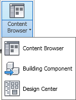
The Content Panel has a single flyout command button, offering three options.The Content Browser option opens, surprisingly enough, Content Browser. If you are keeping score at home, this is the second opportunity you have to do so (see the Tools flyout on the Build panel of the Home tab for the first one). Building component allows you to import “building components” that have been “published” from another application (*.adsk files) as a Multi-View Block, Block or, if you are running AutoCAD MEP, as a Multi-View Part (ImportBuildingComponent command). Design Center, as you can probably guess, opens DesignCenter (despite that extra space in the command button name).

Seek Panel
The Seek Panel offers the ability to use the Autodesk Seek feature (also available in DesignCenter), which allows you to search for product specifications and design files over the Internet.

May 15, 2009

AutoCAD® Architecture 2010 - UI Changes, Part 3.6 - Fixing Context Menu Paste Commands

Thanks to a heads up from Kitetsu07 in this thread in the AutoCAD® Architecture Discussion Group, I can pass on this CUI adjustment to get Paste to Original Coordinates and Paste as Block on the right-click context menu to work in the 2010 release. There is a stray "&" character in the Display Name of these context menu options that results in them being grayed out.
Open up the Customize User Interface dialog (type CUI at the Command prompt, or find it on the Ribbon on the Manage tab, Customization panel), and in the upper left area, under the ACA customization file node, expand Shortcut Menus > Context menu for edit mode > Clipboard. Select the Paste to Original Coordinates item and, in the Properties area (lower right area), delete the "&" in front of "Original" in the Name property under the Display node.
Do the same for the Paste as Block Ctrl+Shift+V item, removing the "&" from between the "B" and "l" of "Block" in the Name property under the Display node.You do, of course, have to have content on the Clipboard that AutoCAD Architecture can paste into a drawing for the Paste as Block option to be active and you need to be in a drawing other than the source file of the objects copied for the Paste to Original Coordinates option to be active. If you would prefer to avoid editing the CUI, you can still type the commands (PASTEORIG or PASTEBLOCK) or use the Ribbon, Home > Modify > Paste flyout on Modify flyout, as shown below.I would rather take the time to fix the CUI, than waste way more than that surfing the Ribbon for these paste options.

May 08, 2009

AutoCAD® Architecture 2010 - UI Changes, Part 3.5 - Tool Palette Command Buttons Alert

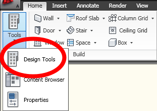
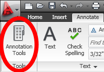
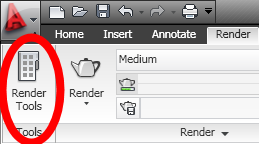
While combing through the AutoCAD® Architecture 2010 preview beta Ribbon tabs and panels, I noticed an inconsistency in the way that the command buttons that set a particular Tool Palette Group current behave. One, the Design Tools button (Home Tab > Build Panel > Design Tools Flyout, main command) will open the Tool Palettes, if they are closed, and, if a Tool Palette Group of the specified name exists, that Tool Palette Group will be set current.Based on the description of the button in the tool tip and my own personal expectations, this is how I would expect the command to run. The other two, Annotation Tools (Annotate Tab > Tools Panel > Annotation Tools) and Render Tools (Render Tab > Tools Panel > Render Tools), however, test to see if the Tool Palettes are open and, if so, close them and do nothing more.If the Tool Palettes are closed, it will open them and set the specified Tool Palette Group current, if a Tool Palette Group of that name exists in the file. While you can simply click the button twice if the Tool Palettes are already open, I do not find this behavior particularly intuitive. If I want to close the Tool Palettes, I can easily select the "X" on the spine of the Tool Palettes. I certainly would not look for a button that would set a Tool Palette Group current and choose that, hoping that the Tool Palettes would close. I do not have access to the shipping version of AutoCAD Architecture 2010 at this time, so I can not tell if this inconsistency was resolved prior to the program release.

[[UPDATE, 2009/05/12: I have seen a shipping version of AutoCAD Architecture 2010, and can confirm that these Ribbon command buttons are set up the same way as they were in the Preview Beta.]]

Fortunately, it is a relatively simple revision to get all three working the same way, whether you prefer the Design Tools approach or the Annotation/Render Tools approach. It does involve editing the CUI, so if this is new territory for you, you may want to make a backup copy of your CUIX file prior to diving in and editing it. That will make it easy to restore what you had, in the unlikely event that something goes amiss or you decide to go back to the way it was as installed. And if you are working off of a network-based CUIX file that you share with others/the rest of the firm (other than an Enterprise CUI), then even if you have write permission, you will want to clear any changes with the powers-that-be (unless, of course, you are the power-that-is).

Got that backup made? Great, then all you need to do is edit the macro string associated with the button(s) you want to change. The Design Tools macro looks like this:
^C^C_AecSetPaletteGroup Design;\
If you want all three to act this way, leave the Design Tools macro as is, and change the Annotation Tools and Render Tools macros to look like this:
^C^C_AecSetPaletteGroup Document;\
^C^C_AecSetPaletteGroup Visualization;\


If you prefer the Annotation/Render Tools functionality of closing the Tool Palettes if they are already open, then leave those macros, which look like this
$M=$(if,$(and,$(getvar,tpstate),1),^C^C_ToolPalettesClose;\, ^C^C_AecSetPaletteGroup Document;\)
$M=$(if,$(and,$(getvar,tpstate),1),^C^C_ToolPalettesClose;\, ^C^C_AecSetPaletteGroup Visualization;\)
alone and change the Design Tools macro to work the same way, like this:
$M=$(if,$(and,$(getvar,tpstate),1),^C^C_ToolPalettesClose;\, ^C^C_AecSetPaletteGroup Design;\)

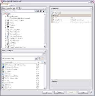
To do this, fire up the CUI dialog (Manage Tab > Customization Panel > User Interface; or type CUI at the command prompt). Make certain you have the dialog fully expanded and that you are on the Customize tab. You should see two columns of editing areas, and the arrow button in the lower right-hand corner should be pointing to the left. If that arrow button is pointing to the right, click on it to expand the dialog to full width.
At the top of the left column ("Customizations in…" area), if you see a downward pointing double arrow at the right side of the title bar, left click on the title bar to expand this area so you can see the various CUIX files that are currently loaded and browse through the various components assigned to each. I am going to assume that you are using the AutoCAD Architecture.cuix file for your Main CUI and that is where the Ribbon is defined. Either select that CUIX file from the dropdown list just below the "Customizations in…" title bar or choose All Customization Files and scroll through the list box to find that CUIX file. If the contents of that CUIX file are not already expanded, click on the "+" to the left of the CUI name to expand the contents, and look for the Ribbon node underneath. Expand that node, and look for the Panels node, which is where the command buttons on each Ribbon Panel are assigned and defined. Find the Panel(s) that have the command button(s) you wish to modify, expand those nodes and find the command buttons you need.
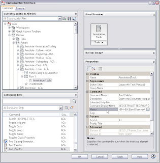
Annotate Tab - Tools Panel - Annotation Tools Button Selected

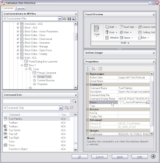
Home Tab - Build Panel - Tools Flyout - Design Tools Button Selected

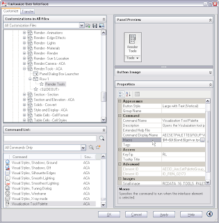
Render Tab - Tools Panel - Render Tools Button Selected

Select the command button you wish to edit. In the upper right side, you should see an image of the button, in the bottom of the right side, you should see a list of properties associated with the button. Edit the button’s macro property (select the Macro property, then select the ellipsis ("...") button at the right of the edit box to open a dialog in which you can edit the contents), replacing what is there with the appropriate macro for the function you desire, as shown above. Repeat for each button you need to change, then click OK in the lower right corner to save your edits to the CUIX file.

Try out your newly configured buttons to make certain they work as expected. If there are problems, reopen the CUI dialog and carefully check you macros, to make certain that there are no typographic errors.

May 06, 2009

Vote for AU 2009 Sessions

Public voting on the sessions that have been proposed for Autodesk University 2009 is now open. You do need to be registered with the AU Online site in order to participate. Go to this page and login using you AU Online user name and password. An access code is not required for public voting. You can submit votes (including comments) on up to twenty sessions. But hurry - there are a lot of session descriptions to read through (even if you limit yourself to the software you use or the topics that interest you) and the voting deadline is this Friday, May 8, at midnight, US Pacific Daylight Time.

If you are planning to attend AU 2009, here is your chance to influence what will be offered. If you can not attend this year, you can still offer your opinion. There will be a "Virtual AU" this year as well, where those who can not attend in person will, for a fee (no information on the cost on the AU Online site as of yet), be able to view virtual sessions that will be video recorded at AU 2009. These sessions will also be "broadcast" at AU, so physical attendees will also have a chance to see them.

Not registered on the AU Online site yet? It is free, and gives you access to AU year-round from your desktop. You can easily create an account here. If you (or your firm) are on Subscription, register through the Subscription website, for access to more (and more recent) AU content.

May 02, 2009

AutoCAD® Architecture 2010 - UI Changes, Part 3 - The Ribbon, Home Tab

The reactions to the full ribbonization in the 2010 release of AutoCAD®Architecture run the gammut from enthusiastic acceptance of the new UI to "What have they done to my program now, and how can I change it back immediately?" I suppose I fall somewhere in between. I have been using Microsoft Office 2007 at work for nearly a year now, and I still find myself muttering under my breath because I can not figure out where they hid the command I want (and used to know where it was). I do not use those programs often enough to quickly master the new UI, and concede I am not enough of a gear head to have spent a lot of time reading up on the theory behind the Ribbon interface/workflow. I will also not be likely using 2010 in a production environment for some time, so it is difficult for me to gage exactly what the impact on my day-to-day work flow would be. What I have seen of it in the 2010 betas leaves me somewhere in the middle, too. I really like the way the contextual tabs pop up and provide access to commands related to a selected object, but am not fully convinced that this is all that much better than the right-click context menus (which have not yet been deleted from the interface). For frequently-used commands on the static tabs, even when I know where to go, it seems like there are at least one or two more clicks to run a command.

For a enthusiast's view of the Ribbon, take a look at Robin Capper's blog article on the Ribbon in AutoCAD Architecture 2010, and keep an eye out for future installments.

Home Tab
Here is what you should find on the Home tab of the AutoCAD Architeture 2010 Ribbon. The images and descriptions posted here are based on the final beta version; it is possible that there could have been some changes made prior to the release of the shipping version. As always, you can click on any reduced-size image to see a full-size version. Use the Back button in your Browser to return here.Build Panel
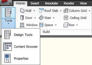
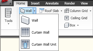
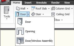
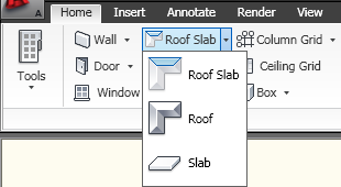
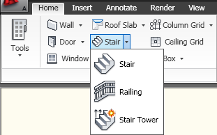
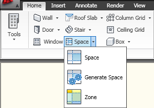
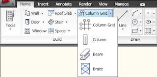
The Build Panel contains commands related to the creation of AEC objects. Note that a down arrow icon indicates that there is a flyout associated with a particular panel or command button. When you hover over a command button that has a down arrow, you will see two "zones" - one with the icon, and the arrow (the background will be darker in the zone over which your cursor is at the moment). Left clicking on the icon will execute that command; left clicking on the arrow will activate the flyout, giving access to the "main" command and additional, related commands. Hovering will display tooltips, if you have those activated, which I would highly recommend, at least until you learn the new icons. For example, the Tools command button at the left of the Build panel displays the Design Tools icon. Selecting that will open the Tool palettes, if closed, and set the Design Tool Palette Group active, if you have a group so named. Selecting the arrow portion displays the following flyout, which also allows you to open Content Browser or the Properties palette, in addition to the Design Tools command.The Wall command button provides access to the WallAdd (main), CurtainWallAdd and CurtainWallUnitAdd commands.The Door command button provides access to the DoorAdd (main), OpeningAdd and DoorWinAssemblyAdd commands.The Window command button does not have a flyout, but does allow you to start the WindowAdd command. The Roof Slab command button provides access to the RoofSlabAdd (main), RoofAdd and SlabAdd commands.The Stair command button provides access to the StairAdd (main), RailingAdd and StairTowerGenerate commands. That last one requires that you be using the Drawing Management system (Project Browser/Project Navigator) and have a project set current.The Space command button provides access to the SpaceAdd (main), SpaceAdd, using the Generate option and ZoneAdd commands.The Column Grid command button provides access to the ColumnGridAdd (main), ColumnAdd, BeamAdd and BraceAdd commands.The Ceiling Grid command button does not have a flyout, but does provide access to the CeilingGridAdd command. Do not forget you need to be in a Display Configuration that has the display of ceiling grids turned on for the current view direction to see the results of this command. The Box command button provides access to the MassElementAdd command, with the BOx option chosen. The flyout provides access to all of the other Mass Element options, except for the Doric and Freeform options (which can be chosen from the Properties palette after excuting any of the other options from the Ribbon), and the DrapeAdd command.Draw Panel
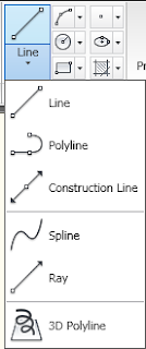
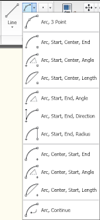
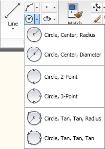
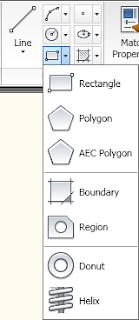
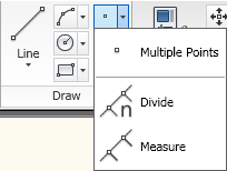
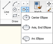
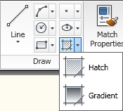
The Draw Panel provides access to the AutoCAD drawing commands that you would have found on the Shapes toolbar in previous releases. One thing to note: The Line button icon, like all of the flyout buttons in the Build panel, will not change if you choose one of the flyout options, but all of the other buttons will change to whatever command you last chose (like a toolbar flyout used to do). The Line command panel provides access to the Line (main), Pline, ConstructionLine, Spline, Ray and 3dpoly commands.The Arc command button provides access to the various ways to specify an arc, with the 3-point method being the initial icon option.Likewise, the Circle command button provides access to the different ways you can create a circle, with the initial icon running the Center, Radius option.The Rectangle command button runs the Rectang command from the initial icon and also gives access to the Polygon, AecPolygonAdd, Boundary, Region, Donut and Helix commands.The Multiple Point command button provides access to the Point, Divide and Measure commands.The Center Ellipse command button provides access to the Ellipse command, with the center option chosen, the Ellipse command and the Ellipse command, Arc option chosen.The final command button on the Draw Panel gives access to the Bhatch and Gradient commands.Modify Panel
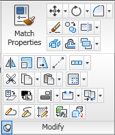
The Modify Panel has a number of object modification commands, including a number on the panel flyout which are accessed by selecting the panel name. The "pin" that displays at the left end of the panel name when the flyout is displayed can be selected to pin the flyout in the open position.The featured Match Properties icon runs the MatchProp command. The smaller icons, starting at the top and running left-to-right, row by row, allow you to run [Row 1] the Move/3dmove, Rotate/3drotate, Fillet/Chamfer, [Row 2] Erase, Copy, LineworkTrim/Trim/LineworkExtend/Extend (the "Linework" variants are the AEC enhanced commands), [Row 3] Explode, Offset, DrawOrder (Bring to Front, Send to Back, Bring Above Objects and Send Under Objects), [Row 4, on flyout] Mirror, Scale, Stretch, Lengthen, LineworkArray/Array/3darray, [Row 5] Cut, CopyClip/CopyBase/CopyLink, PasteClip/PasteBlock/PasteAsHyperlink/PasteOrig/PasteSpec, LineworkObscure/LineworkCrop, [Row 6]SetByLayer, Chspace, Align/RepositionFrom/LineworkSpaceEvenly/LineworkCenter/LineworkDivide, Break/Break at Point/Join, LineworkMerge/LineworkSubtract, [Row 7] Pedit/SplineEdit/HatchEdit/MassElementConvert/ConvertTo3DSolids

Layers Panel
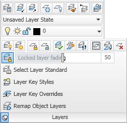
The Layers Panel collects all layer-related commands. The top row features command buttons for the Layer, Layiso, Layuniso, Layfrz, Layoff (an unfortunate command name, given the current state of the global economy), Laymch, Layerp, and Laymcur commands. The button on the second row displays the name of the current Layer State, and when the flyout is activated, allows you to select from a list of defined layer states, create a new layer state or manage layer states. The button on the third row displays the equivalent of the layer dropdown from the former layer toolbar. New in 2010, you can now click on the color swatch and change the color of a layer directly from here, without the need to open the Layer Properties Manager.The fourth row (first row of the flyout) has command buttons for the Layon, Laythw, Laylck, Layulk, Laycur, CopyToLayer, Laywalk, Layvpi (freezes a layer in all other viewports), Laymrg and Laydel commands. The fifth row has command buttons that allow you to toggle locked layer fading on and off and set the amount of fading of locked layers when turned on. The sixth row runs the AecDwgLayerSetup command, opening the Drawing Setup dialog to the Layering tab. The seventh row opens the Style Manager, filtered for Layer Key Styles. The eighth row opens the Layer Key Overrides dialog, allowing you to set a Layer Key Style current, set overrides on the fields defined in the Layer Standard associated with that Layer Key Style and enable/disable all Layer Key Overrides. The ninth row runs the RemapLayers command, which will put selected AEC objects back on the layer associated with the Layer Key assigned to that object type.

Annotation Panel
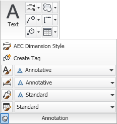
The featured Text icon on the Annotation Panel runs the Mtext command. The first row command buttons give access to assorted AEC Dimension and AutoCAD Dimension commands and AnnoRevisionCloudAdd/MaskAdd/Wipeout. The second row contains command buttons for Mleader/AIMleaderEditAdd/AIMleaderEditRemove/MleaderAlign/MleaderCollect and various reference/sheet keynoting and keynote legend choices. The third row allows you to add a number of Schedule Tags (these are linked to the ones available in the tool palettes; I believe these can be customized to tags present in your own tool palettes) and the DefineTag command and add various Schedule Tables (again, linked to those in the tool palettes)/open Style Manager filtered for Schedule Table Styles and add an AutoCAD table.The fourth row (first in the flyout) opens the Style Manager, filtered for AEC Dimension Styles. The fifth row offers another location to run the DefineTag command. The sixth row gives access to the Style command, with a dropdown list to set the current text style. The seventh, eighth and ninth rows do the same for dimension styles, multileader styles and AutoCAD table styles.

Inquiry Panel
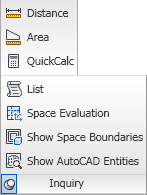
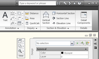
The Inquiry Panel provides access to the Distance option of the MeasureGeom command (which seems so much more cumbersome than the good old Dist command, although it does have fancier on-screen graphics), the Area option of the MeasureGeom command (similar comment with respect to the Area command), the QuickCalc commandand, in the flyout, the List, SpaceEvalutation, SpaceShowBoundingObjects and VisualAudit commands.

Section & Elevation Panel
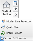
The Section & Elevation Panel has command buttons for the VerticalSection, HorizontalSection, BldgSectionLineAdd and BldgElevationLineAdd commands and, in the flyout, the CreateHLR, QuickSlice and RefeshSectionsElevations commands.

Details Panel
The Details Panel has a single command button for the DtlCompManager command, which opens the Detail Component Manager dialog.View Panel
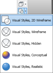
The View Panel has three flyouts, the View flyout,the Visual Styles flyoutand the Zoom flyout.These should be familiar as there were formerly toolbars for each of these.

The frequency with which I use these commands leads me to believe that I will usually "tear off" this panel and leave it as a floating panel.A panel can be torn off by selecting the panel title and, while holding down the left mouse button, dragging it off of the Ribbon. Doing so will make it available at all times, even when another Ribbon tab is current. If you hover over the torn-off panel, it will "grow wings".The left side provides a place to grab and move the panel (you can also do so by selecting and holding down the left button on the panel title). The right side has two icons; the top one will return the panel to the Ribbon, the other will toggle the orientation of the panel/title from horizontal to vertical.