Showing posts with label New Features. Show all posts

April 25, 2017

ACA/AMEP 2018: New Features Part 2

File Navigation Dialogs
The dialogs for commands that ask for a file to be selected or a folder for a file to be saved, such as the OPEN, ATTACH and SAVEAS commands, will now retain any column sort order you set from one use to the next. Each "type" of file dialog has a separate sort setting. SAVE and SAVEAS will share the same sort, but ATTACH can be different, and must be set separately. The sorting is remembered across sessions of AutoCAD, also.

Drafting Settings Dialog
This dialog is now resizable.

Quick Access Toolbar and the Layer Control
The Layer Control has been added to the list of tools that can be added to the QAT by using the drop-down list at the right end of the toolbar. It is turned off initially, but is there on the drop-down list, waiting for you to select it, if desired.

System Variable Monitor on the Status Bar
The System Variable Monitor tool will appear in the tray at the right end of the Status Bar when a System Variable that is being monitored is changed from its preferred value. In previous versions, you could left click on this tool, and the System Variable Monitor dialog would open, allow you to review the settings and status, and reset all monitored variables to their preferred values. You can still do that in 2018; new is the ability to right click on the tool to get a context menu with three choices:
  • Configure System Variable Monitor: Selecting this is the same as left clicking on the tool.
  • Reset System Variables: Reset all monitored System Variables to their preferred values without opening the dialog.
  • Display Notification: Balloon notification of changes to monitored System Variables is turned on if there is a check mark in front of this item. Select this item from the context menu to remove the check mark, if present, or to add the check mark, if absent.

Off-screen Selection
If you start a selection window when zoomed in, and have to either pan or zoom out/zoom in to another section of the drawing to select the opposite corner, such that your first corner is now off screen, the off-screen objects encompassed by the selection window will now be selected.

Linetype Gap Selection Improvements
The ability to select objects with a non-continuous linetype, or have the gaps in the linework of such objects be recognized by commands like EXTEND has now been extended to both complex and DGN linetypes. Complex linetypes are those that have text or shapes embedded into the linetype. This feature also now works for all object types, including Splines and Polylines with non-zero width.

Share Design View Enhancements
Introduced with the 2017 release (on the A360 ribbon tab, on the Share panel, select the Share Design View tool to start the process for the current drawing, which must be saved), this feature allows you to upload a drawing file to an anonymous location in the Autodesk A360 cloud, and then share views of the drawing with others, who only need to have a supported browser (Chrome, Firefox and other browsers supporting WebGL 2D graphics) to view the file. The actual DWG file is not made available, just the ability to view it. By default, uploaded files expire in 30 days; newly added is the ability to find previous uploads and to extend the expiration date, if desired.

April 22, 2017

ACA/AMEP 2018: New Features Part 1 - External Reference Improvements

I usually start out my first "new features" article for a given release by remarking that I have been busy, and apologizing for the delay in preparing the article. While I am indeed busy this year as well, and that has contributed to the tardiness of this article, another contributing factor is my lack of enthusiasm over the lack of new AutoCAD® Architecture and AutoCAD® MEP features in the 2018 release. My understanding is that you all (meaning, all of you end users out there) have been telling Autodesk that you would rather have them fix things that need fixing in the existing features, rather than adding new features. While I like fixing bugs or adjusting the design of a feature to better suit typical industry workflows as much as the next person (maybe more so), in my mind most of that effort should be in the province of a service pack or hotfix, unless it truly is a major change from the original feature design and the original feature design more or less worked as designed. This is particularly upsetting given that the pain of a new file format is being inflicted, without any offsetting new features that required a new file format to implement.

So, a number of items that had been reported as not working as expected have been fixed. Support for 4k monitors has been integrated for AutoCAD Architecture and AutoCAD MEP dialogs, palettes, etc. (I do not have 4k monitors, so I am taking their word on that.) And, all of the wonderful new things added to the core AutoCAD feature set have been integrated into AutoCAD Architecture/MEP. The balance of this article will look at the improvements made to external references.

External Reference Improvements
  • Relative path is the new default when attaching an externally referenced file to a drawing. Use the REFPATHTYPE System Variable to set a different default path type: 0 = No Path, 1 = Relative Path and 2 = Full Path.
  • Use of a relative path for an externally referenced file no longer requires that the host file be named/saved. Instead, the full path will temporarily be shown in the Saved Path column, with a preceding "*" and, in the Details section, the Pending Relative Path property will show as "Yes". Once the file is saved, any pending relative paths will be resolved and show the relative path in lieu of the temporary full path.
  • If you save a file to a new location and that file has relatively pathed external reference files attached, you will be prompted as to whether or not the relative paths should be updated for the new location. If you only plan to save this one file to the new location and you want the relatively pathed external references to be found, you will most likely want to update the relative paths. If you eventually intend to move (or copy) the relatively referenced files such that they will be in the same relative location, then not updating the paths may be the appropriate choice.
  • There are two new right-click contextual menu choices when dealing with an externally referenced file that is "not found".
    • Select New Path: This option provides the opportunity to browse to a new location (path) for the "not found" file. If there are additional "not found" external references, you will be asked if the new path should be applied to those, as well.
    • Find and Replace: This option allows you to select one or more external references and then specify a target path (Find saved path) and specify a replacement path (Replace with). For ONLY the external references that were selected when you right clicked and chose Find and Replace, AutoCAD will look for any that have the target path and will replace that path with the replacement path.

      If all of the selected external references currently have the same path, that path will be offered as the initial default in the Find saved path edit box. If you select external references with different paths, you will have to supply both the Find and the Replace paths. Note that if you use the ellipsis button at the right side of either edit box, you will get the full path of the selected folder, regardless of the path type shown in the Find edit box, or the path type used for the selected external references. You can manually edit that path to be a relative path, if desired. If the external reference uses a relative path, providing the equivalent full path in the Find box will not result in a match. In limited testing, providing the full path as the Replace path for an external reference that is currently set to relative path did result in the relative equivalent to that full path being applied.

      Find and Replace also appears on the right click context menu when selecting "found" external references and can be used to repath multiple references at one time (provided that the current and replacement paths are the same for all selected external references). Note also that the text entered in both edit boxes has to be an actual path. You cannot just enter the text you want to replace in the Find edit box and the text that you want to substitute in the Replace edit box; the complete path must be used in both (whether a full path or a relative path).

  • When right clicking on one or more selected references and using the Change Path Type context menu item, if all of the selected items currently have the same path type, that path type will be disabled in the cascading contextual submenu. If there are multiple path types in the selected references, then all three options will be enabled.
  • The Open option right click context menu option is no longer disabled for unloaded external references.
  • If you rename an unloaded external reference on the External References palette, it will no longer automatically be reloaded. You will need to reload the reference in a separate action if and when you want it reloaded. Note: As in previous versions, using the RENAME command, and the Rename dialog, to rename an unloaded external reference will leave the external reference unloaded. New in 2018, if you use the Rename dialog or the CLASSICXREF command's Xref Manager to rename an external reference, that change will show immediately in the Reference Manager palette, without the need to reload the renamed reference.
  • There has also been a minor change to the dialog that appears when opening a drawing with external references that cannot be found. Instead of referring to these files as "missing", they are now noted as "Not Found". The text on the button that opens the Reference Manager has also been simplified.

March 28, 2015

ACA/AMEP 2016: Styles Browser Part 2

The Styles Browser Interface (Continued)
Part 1 focused on the top part of the Styles Browser; this article will examine the style/defintion list box and related controls.

The Styles Browser has a tool bar at the top of the style/defintion list box. Three tools at the right side of this bar control how the styles/definitions are viewed: Preview Size, View Direction and Color Selection. As seen in the image below, the Preview Size tool has a drop-down list which offers four viewing choices: Small, Medium and Large preview images and Details, which shows just names and descriptions in text. Note that selecting the Details option will disable the View Direction and Color Selection tools, as these settings do not apply to the Details view. The icon of the currently selected tool is displayed on the tool button.

The View Direction tool has a drop-down list which offers the six standard othogonal and four standard isometric view directions. The initial default view direction varies with the Object Type selected. As with the Preview Size tool, the icon of the currently selected view direction is displayed on the tool button.

The Color Selection tool has a drop-down that allows you to select the background color of the preview images. The None option uses the palette background color. You can choose from a range of color swatches, including AutoCAD® index colors 1-9, or choose the More Colors option at the bottom to open the standard color selection dialog, offering the full range of Index colors, True Color and Color Books. A Recent Colors section is offered if you choose a color not offered on the pull-down. Setting a background color other than None (such as matching your AutoCAD background color) may be useful if you find it hard to see the preview graphics images with the Styles Browser background color.

When AEC Dimension, Display Theme or Zone are chosen as the Object Type, the tools at the right end of the tool bar will all be disabled, as the only view option for these is Details.

Hovering over a style or definition in the list box will display a Tool Tip, whether or not Tool Tips are enabled in the Options dialog, on the Display tab. Most styles/definitions have a two-stage tool tip; the first stage is all text, listing the style/definition name, description and the source file (or Current Drawing for styles/definitions in the current drawing). If you hover longer, the Tool Tip will expand to include image previews showing that style/definition in isometric, left, front and plan views. There is no expanded Tool Tip with graphics for the AEC Dimension, Display Theme and Zone Object Types.

The tools at the left side of the tool bar control the use of the styles/definitions displayed in the Styles Browser: Import styles, Add object and Apply style to selection. Selecting one of the styles or definition in the list box enables the relevant tools. The Import styles tool will be inactive if a style/definition from the current drawing is selected. The Apply style to selection tool will be inactive if no objects of the selected Object Type are selected in the current drawing. The same three options are available in a context menu when you right click on a style or definition. You can also double click on a style/definition to initiate the ADD command for that object type, using the selected style/definition (imported into the current drawing, if necessary).
When all of the objects that are selected in the current drawing are of the current Object Type and are all of the same style/definition, then that style/definition will be outlined in blue. When a style is selected, the entire style is highlighted in blue. If the cursor moves off of the palette, the blue color is removed, but the selected tool remains highlighted. If you wish to clear the current style/definition selection, press the ESC key.

If the current drawing already has a style/definition of the same name as one in a source file, a green checkmark will appear next to the style(s)/definition(s) in the source file(s). You will not be able to import these styles, and if you choose the Add or Apply options for these styles, the style/definition in the current drawing will be used. You cannot use the Styles Browser to update a style in the current drawing with one of the same name in a source file. Use the Style Manager to do this, when necessary.

All of the usual options for displaying a palette apply to the Styles Browser: Transparency, Auto-hide, Docking and Anchorage. Right click on the palette title spine and use the context menu to choose your display options.

The Styles Browser provides easy access to styles and definitions from office standard source files, project standards files and currently open drawings, without the need to create or maintain an extensive set of tool palettes and tools. When you upgrade to AutoCAD® Architecture 2016, try it out and see if it can improve your workflow.

March 25, 2015

ACA/AMEP 2016: Styles Browser Part 1

A new modeless (can be open while executing other commands) palette has been added to the 2016 releases of AutoCAD® Architecture and AutoCAD® MEP, the Styles Browser. You can use the Styles Browser to quickly review the AEC object styles available in your choice of Content Library Drawings, Project Standard Drawings or Currently Open Drawings. Once you find the desired style, you can import it into the current drawing, add an object using the selected style or assign the selected style to an object of that type already in the drawing. Using the Styles Manager, you can avoid the need to create and maintain a Tool palette tool for every office standard style while still providing easy access to those styles. You can easily add additional source files, when needed for a specific project, to provide access to project-specific content without creating project-specific Tool palettes.

Opening the Styles Browser
As with most everything AutoCAD-related, there are a number of ways to access the Styles Browser.
  • From the ribbon: On the Home ribbon tab, on the Build panel, select the bottom half of the Tools split button, and then choose Styles Browser from the context menu.
  • From the Command line: Type STYLESBROWSER and press the ENTER key.
  • From the Properties pallete with a style-based AEC object selected: On the Design tab, under the Basic category, under the General subcategory, with the Style Preview active, select anywhere in the Style Preview area.
  • From the Properties pallete with a style-based AEC object selected: On the Design tab, under the Basic category, under the General subcategory, with the Style Preview inactive, on the Style property, select the Select a style button (binoculars icon) at the far right side.
As noted for the last two methods using the Properties palette, you must have a style- or definition-based AEC object of a type that is supported by the Styles Browser (see below). When using these methods, the Styles Browser will open with the Object Type pre-set to the type of object selected, with that object's style selected.

The Styles Browser Interface
The top portion of the palette contains three pull-down lists, a Search Style edit box and a button to open the online help to the Styles Browser topic. The selections made in the pull-downs and the search string entered into the edit box, if any, will determine the styles/definitions that you will be offered in the style list box below. While you can visit the pull-downs in any order, it makes the most sense to start from the top and work your way down, in order, as the choices available in the third list will be affected by what is set in the first two.

The Object Type pull-down contains a list of all of the object types that are supported in the Styles Browser, divided into separate sections for Architectural Objects, Documentation Objects and Multi-Purpose Objects. Use the +/- button at the left side of the section headers to expand or contract each section. Select the object type on which you wish to operate. The image below is a composite to show the entire list.

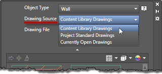
The Drawing Source pull-down offers up to three options for determining the possible drawing sources for styles: Content Library Drawings, Project Standard Drawings or Currently Open Drawings. Content Library files are user-selected files that contain "office standard" styles. These can include the same files you use as source files for your Tool palette tools, and the initial list includes the out-of-the-box style source files. (See below for more on this.) Project Standard Drawings will only be included on the list if you have an ACA Project (Project Browser/Project Navigator) open. As you might expect, Currently Open Drawings will make the styles/definitions in all currently open drawings available.
The third pull-down, Drawing File, allows you to further refine the source files used for the styles/definitions that are displayed. The choices here will vary with the Object Type and Drawing Source selected in the first two pull-down lists. The list starts with All Drawings, which will include all of the drawings included in the selected Drawing Source, plus the current drawing. Current Drawing will only show items from the current drawing. All Without Current Drawing will show styles/definitions only from the file(s) from the specified Drawing Source, but will not include those in the current drawing. These three choices will then be followed by the individual file(s) from the specified Drawing Source, allowing you to limit the items shown to just that one drawing.
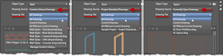
When using Currently Open Drawings as your Drawing Source and only one drawing file open, selecting All Without Current Drawing in the Drawing File drop-down list will result in an empty style/definition list box, since there are no other drawings open. You can only select one item from the Drawing File dropdown list, so you will not, for example, be able to hold down the CTRL key and choose two individual drawings. Similarly, if Project Standard Drawings is selected as the Drawing Source when Project Standards is disabled for the current Project, choosing All Without Current Drawing in the Drawing File drop-down list will also result in an empty style/definition list box.

The final means of affecting the styles/definitions that are shown in the style list box is the Search Style edit box. Any text entered here is compared to the names of the styles/definitions that meet the criteria of the choices made in the three pull-down lists, and only those that match the string are shown. Any portion of the name may be entered; for example, in the image below, only the Wall Styles that have the text Air-2 somewhere in the style name are shown. The entered text is treated as a wild-card string, with an * before and after the text. You cannot, however, type wildcard characters as part of the search string; all typed characters are interpreted literally.

As previously mentioned, you can customize the drawings included when Content Library Drawings is the selected Drawing Source. To do so, select Content Library Drawings as the Drawing Source, and then select the Drawing File pull-down list. At the bottom of the list, select the Manage Content Library button. This will open the Content Drawings Library dialog, in which you can add or remove drawing files from the list of source files for the Object Type selected in the top drop-down list. Make note of the Save as default toggle in the lower left corner. With this toggle unchecked, you can make "temporary" changes to the list of content drawings by adding and/or removing files and selecting OK. For example, if your current project does not have any Walls with brick components, you could remove the brick Wall source file from the list temporarily. Any "temporary" changes will persist, even after closing and reopening the program. You can, however, restore the saved list by reopening the Content Drawings Library dialog and using the Restore button. If you want to change that saved list, make the desired changes, check the Save as default toggle and then select OK.

Once you have made your selections in the drop-down lists, you may wish to save some of that vertical space in the palette. You can do so by selecting the button with the upward pointing arrowhead icon, bewteen the Search Style edit box and the style/defintion list box. This will leave only the Object Type pull-down list and expand the area available to list box. In the collapsed state, you can make changes to the Object Type selection. If you do so, the Drawing Source and Drawing File choices will remain the same, but any text in the Search Style edit box will be cleared. Select the button again (now with a downward pointing arrowhead), to expand the filter controls if you want to make changes or add text to the Search Style edit box.

The final feature in the top portion of the palette is the Help button (speech bubble icon with ?), which provides direct access to the online help topic on the Styles Browser.

In Part 2, the features associated with the style/definition list box, and the ways of using the Style Browser will be covered.

March 21, 2015

ACA 2016: Quick Notes

Here are some quick thoughts on the upcoming 2016 release of AutoCAD Architecture, while you wait for more in-depth articles on new features.

No change in file format!

Same interface color scheme choices as 2015 (truly dark Dark and Light).

The Drawing Window Status bar has now been completely removed from ACA and AMEP, and the tools that had been there in 2015 - Display Configuration control, Cut Plane control and System Tray - have been moved to the Application Status Bar, which is now referred to as the Status Bar. The "Cut Plane" text in the Cut Plane control has been replaced with an icon, and the control will only be displayed when Model Space is active. The STATUSBAR system variable now only supports values of 0 (Status Bar off) and 1 (Status Bar on). The Status Bar will now also wrap onto a second row if more tools are turned on that will fit on a single row.


The "New Tab" has been renamed to "Start". The content on both the Create and Learn pages of the Start tab is similar to the 2015 New Tab. (In 2016, I have a Notifications area that is not present in 2015 - I am not certain if that is new, or that I just do not have any current notifications in 2015.)

The Start tab remains available even after you start a new drawing or open and existing one, unlike the New Tab in 2015. It does not have a close button ("X") at the right end of the tab, like drawing tabs (and the 2015 New Tab) do. For those who would prefer to do without the Start tab, the former NEWTABMODE system variable from 2015 has been renamed to STARTMODE. Set it to 0 to close the Start tab and disable it on future launches. Set it to 1 to re-enable the Start tab. Note that when changing the value from 0 to 1, you will have to close and restart the program to get a Start tab; one will not immediately appear in the interface after changing the value to 1. There is no equivalent of the old NEWTABMODE setting of 2, which allowed the "+" button to the right of the tabs to open a new file based on the default template, rather than creating another New Tab (NEWTABMODE = 1 behavior). Since the Start tab is now either always on or always off, the "+" button always opens a new file based on the default template (or opens a dialog asking you to select a template file if no default template is specified). When creating a deployment, you have the option to enable or disable the display of the Start tab.

New CLOSEALLOTHER command allows you to close all but the current drawing tab from the command line. As in 2015, you can also right click on any drawing tab and choose the Close All Other Drawings to close all drawing tabs other than the one on which you right clicked (which does not have to be the current drawing tab).

Coordination models created in Navisworks (NWD or NWC files) can now be attached to a drawing using the means use to attach other reference files (DWGs, DGNs, PDFs, image files, etc.), as well as the new CMATTACH command (-CMATTACH for the command line version). If the current drawing file is included in the coordination model, you have the option to turn off the current drawing's geometry in the coordination model. You can also apply color fading and opacity fading to the coordination model, to improve your ability to distinguish between the coordination model and the current drawing geometry. This feature requires a 64-bit system, with hardware acceleration turned on.

October 30, 2014

New Features Links

From time to time, questions are raised as to what new features have been added between Release X and Release Y. I try write about the new features at the time of each release (or, at the least, the new features that interest me), but have never collected links to all of those in one place. To make it easier for me to refer to them, and for others to find them, this post will become an index to the new features posts. I will place a link to it under the Oldies But Goodies section at the right side of the blog.

ACA 2018
ACA/AMEP 2018: New Features Part 1 - External Reference Improvements
ACA/AMEP 2018: New Features Part 2

ACA 2017
ACA 2017: Grip Editing of a Roof Object Outline
ACA 2017: CReate type Command Option
ACA/AMEP 2017: Styles Browser Enhancements

ACA 2016
ACA 2016: Quick Notes
ACA/AMEP 2016: Styles Browser Part 1
ACA/AMEP 2016: Styles Browser Part 2
ACA/AMEP 2016: Section Enhancements
ACA/AMEP 2016: Property Visibility Override

ACA 2015
ACA 2015 - New Look
ACA 2015 - Style Import
ACA 2015 - Version Management in Project Navigator
ACA 2015 - Visual Comparison
ACA 2015 - Command Preview
AutoCAD 2015 - Cursor Badges
ACA 2015 - Highlighting and Selection Preview

ACA 2014
ACA 2014: Property Set Defintion Auto-attach
ACA 2014: Command Line Search
ACA 2014: Door and Window Placement
ACA 2014: Tools from the DACH Extension
ACA 2014: Additional New Features/Improvements

ACA 2013
ACA 2013 - Grouping and Subtotals in Schedule Tables
ACA 2013: Object Display Enhancements Part 1
ACA 2013: Object Display Enhancements Part 2
ACA 2013: Object Display Enhancements Part 3
AutoCAD 2013 - Command Line Enhancements

ACA 2012
ACA 2012 New Feature - Corner Windows
ACA 2012 Enhanced Feature - Column Grids
AutoCAD 2012 New Feature - In-Canvas View Controls
AutoCAD 2012 New Feature - AutoComplete

ACA 2011
AutoCAD® Architecture 2011 Overview
Selection Cycling
ACA 2011 - Opening Location Changes - Part 1
ACA 2011 - Opening Location Changes - Part 2
ACA 2011 - Opening Location Changes - Part 3
ACA 2011 - Opening Location Changes - Part 4

ACA 2010
AutoCAD® Architecture 2010 - Editing Wall Cleanup In Place
More AutoCAD® Architecture 2010 Features
AutoCAD® Architecture 2010 - UI Changes, Part 1 - The Application Menu
AutoCAD® Architecture 2010 – UI Changes, Part 2 – Resizing the Ribbon
AutoCAD® Architecture 2010 - UI Changes, Part 3 - The Ribbon, Home Tab
AutoCAD® Architecture 2010 - UI Changes, Part 3.5 - Tool Palette Command Buttons Alert
AutoCAD® Architecture 2010 - UI Changes, Part 3.6 - Fixing Context Menu Paste Commands
AutoCAD® Architecture 2010 – UI Changes, Part 4 – The Ribbon, Insert Tab
AutoCAD® Architecture 2010 – UI Changes, Part 4.5 – Ribbon Tools
AutoCAD® Architecture 2010 – UI Changes, Part 5 – The Ribbon, Annotate Tab
AutoCAD® Architecture 2010 – UI Changes, Part 6 – The Ribbon, Render Tab
2010 File Format Change
AutoCAD® Architecture 2010 - UI Changes, Part 7 - The Ribbon, View Tab
AutoCAD® Architecture 2010 - UI Changes, Part 8 - The Ribbon, Manage Tab

ACA 2009
AutoCAD Architecture 2009 - Part 1
AutoCAD Architecture 2009 - Part 2
AutoCAD Architecture 2009 - Part 3
AutoCAD Architecture 2009 - Part 4
Space Generation in ACD-A 2009 with AutoCAD® Object Boundaries

ACA 2008
No More LTSCALE/PSLTSCALE Problems!
Annotative Tags With Leaders in ACA 2008
I appear to have been distracted in 2007, and did not write extensively about the new features in ACA 2008. You can read about three 2008 features that were at the top of Matt Dillon's list in his blog, here.

ADT 2007
ADT 2006 Tags
Enhanced Property Data Features in ADT 2007, Part 1
Enhanced Property Data Features in ADT 2007, Part 2
Enhanced Property Data Features in ADT 2007, Part 3
Enhanced Property Data Features in ADT 2007, Part 4
Enhanced Property Data Features in ADT 2007, Part 5
ACA 2008/ADT 2007: Setting a Different Property Data Format in a Formula Property

ADT 2006
ADT 2006 Tags
ADT 2006 Tags Illustrated
Formula Property Interface Improved in ADT 2006
Selection Previewing in ADT/AutoCAD 2006
Selection Previewing Update