December 16, 2015

Revit: CAD Export Layer Mapping - Restore Subcategory Default

When editing a DWG/DXF Export Setup, you may have noticed that some subcategories have the layer name of the main category, enclosed in curly braces ("{" and "}") and italicized, and, if you change the layer name of the main category, these all automatically update to match that change in the main category. For example, using the Revit 2014 out-of-the-box US Imperial default.rte template, the Doors category looks like this:

Notice that the Elevation Swing and Plan Swing subcategories have { A-DOOR } in the Layer column, whereas the Panel subcategory just has A-DOOR. If the layer for the Doors main category is changed, the Elevation Swing and Plan Swing subcategories also change, but the Panel subcategory does not.

If you want a subcategory to be linked to the main category name, but it is not already so linked, you can do one of the following:
  • If there is already another subcategory so linked, you can copy the text in that subcategory, and then paste that value into the subcategory you wish to link. Be certain to copy the entire string, including the leading space characters.
  • If there is not already a linked subcategory, or you just prefer typing to cutting and pasting, type two space characters, an opening curly brace ("{"), one space character, the layer name as it currently appears in the main category, one space character and a closing curly brace ("}"). Once you press the ENTER key or click into another field, the text will italicize, letting you know you entered it correctly.
  • You can also just type two space characters, an opening curly brace ("{"), two space characters and a closing curly brace ("}") in the subcategory's Layer field, and then make a change to the main category's layer name, if that is easier for you. After you change the main categories layer name, you can change it back if you did not want to make a change to it.
As always, click on an image to see a larger version of it.

December 04, 2015

ACA: Underline in Tag But Not in Schedule III

This old post and this follow up post describe two ways to have a text property shown in a tag (such as a room name) be underlined in the tag, but not in a schedule table. The first post suggested adding a formula property, and concatenating %%u and the non-underlined property in the formula, and then using the formula property in the tag.

The second post accomplished the same thing by making a copy of the Property Data Format assigned to the text property and, in the copy, adding %%u in the Prefix field, and then assigning the new Property Data Format to the property in the Property Set Definition. When adding that property to a Schedule Table Style, the original, non-underlined Property Data Format would be used. The benefit of this method is that you do not need to make any changes to the view block used by the Schedule Tag's Multi-View Block Definition.

This all worked fine back in 2005/2006 when the articles were written, and for some time thereafter. I have not checked, but I suspect that the addition of multi-line attribute support for Multi-View Blocks (and, therefore, in Schedule Tags) in the 2009 release broke the recognition of %%u as a code to indicate starting (and stopping) an underlining of text. It certainly does not work in the 2016 release.

Fortunately, there is still a way to do this, and it can be used with either method. Just substitute \\L [the MText underline code] for %%u. For example, given a text property called Name, you could create a formula property that creates an underlined version of that property by using the formula
RESULT = "\\L" & "[Name]"
where "[Name]" is a properly created reference to the Name property.

Or, you could make a copy of the Property Data Format, such as Case - Upper, rename the copy Case - Upper - Underline, and add \\L to the Prefix property on the Formatting tab.

November 21, 2015

ACA: Unexpected Thawing and Turning On of Layers

If you are using AutoCAD® Architecture 2015 and 2016, you place AEC Objects on layers other than the layer associated with the default Layer Key for that object type and you have occasion to turn off and/or freeze the layer associated with that default Layer Key, you may have found that simply selecting one of the objects on one of the other layers will result in the layer associated with the default Layer Key being turned on and thawed. This makes it difficult to work with just the items on the "other" layers. One situation where this would be desirable is on a renovation project, where you have the existing-to-remain, existing-to-be-demolished and new construction objects all in the same file, and you want to view and edit the demolition plan. To do so, you would turn off and/or freeze the new construction layers, and would not expect these to turn back on and thaw just because you select an item on the existing-to-remain or existing-to-be-demolished layers.

For example, you may have a file where the WALL layer key is associated with a layer named A-Wall-N, on which new construction Walls are placed. A layer named A-Wall-E is used for existing-to-remain Walls, and existing-to-be-demolished Walls are placed on a layer named A-Wall-D. As seen in the Screencast below, if the A-Wall-N layer is frozen and turned off, selecting a Wall on the A-Wall-D layer will result in the A-Wall-N layer being turned on and thawed. A REGEN is needed to see this immediately, since the layer had been frozen, but you can also check the Layer Properties Manager to see that the layer has, in fact, been turned on and thawed.

The 2014 release did not exhibit this behavior, as shown in the second half of the Screencast. Note also that if you select multiple object types at one time, only the layer associated with the default Layer Key of the first object type selected will be turned on/thawed.

November 07, 2015

Exception in mc3.dll / mc3d.dll ARX Command

If you are running AutoCAD® Architecture 2016 or AutoCAD® MEP 2016, and get this error message after working in the program for a few minutes
then you have a damaged WHITELIST.XML file, which is used in connection with the Desktop Analytics and Customer Involvement Program features.

This Autodesk Knowledge Network [AKN] article describes the issue and provides a procedure to fix the problem. In brief, with the program closed, you delete the damaged WHITELIST.XML file, reboot your computer, and then restart AutoCAD Architecture or AutoCAD MEP. Turn Desktop Analytics and the Customer Involvement Program features back on, if you turned them off, by selecting the right side (down arrow icon) of the Help split button, and choosing the Desktop Analytics and Customer Involvement Program items (one at a time). After several minutes, the WHITELIST.XML file should be downloaded from the Autodesk website (if you have an active internet connection). This file should not be damaged, and you should not experience the Exception in mc3.dll / mc3d.dll ARX Command error message.

An alternative solution to stop the crashing is to use those menu items to turn off both Desktop Analytics and the Customer Involvement Program. The AKN article describes how to do so via editing the registry if you are unable to open the program and get to the Help Menu.

NOTES:
  1. In order to get the full Help drop-down menu, you need to have at least one drawing file open. Just having the Start tab open will result in a truncated menu that does not include the Desktop Analytics and Customer Involvement Program items.
  2. As of November 7, 2015, the AKN article lists this folder as the location of the WHITEPAPER.XML file for AutoCAD Architecture 2016:
    C:\Users\[user]\AppData\Roaming\Autodesk\ARCHDESK\2016\{5783F2D7-F004-0409-2102- 0060B0CE6BBA}\7.8.44.0\MC3
    I had that folder, but there was not a WHITEPAPER.XML file in it. I found it in this folder, instead:
    C:\Users\[user]\AppData\Roaming\Autodesk\ARCHDESK\2016\{5783F2D7-F004-0409-2102-0060B0CE6BBA}\7.8.106.0\MC3
    The difference between the two is the product version number folder. I had SP1 for AutoCAD Architecture 2016 installed, and 7.8.106.0 is the version number after SP1 is installed. You may want to check the About AutoCAD Architecture 2016 dialog (last item on the Help drop-down menu) to see what your version number is, and look for the WHITEPAPER.XML file in the folder with that number.
  3. After not finding the WHITEPAPER.XML file in the ...\7.8.44.0\MC3 folder, I tried searching my entire C: drive for WHITEPAPER.XML. Windows will apparently not search inside all (any?) of the User folders when the search is started at the root of C: drive, as I got no hits when doing so. After I saw the file in the ...\7.8.106.0\MC3 folder, I tried searching from the C:\Users\[user]\AppData\Roaming\Autodesk folder and then it found the file.

October 07, 2015

Dynamo Primer - Update

First Edition V1.2 of the Dynamo Primer is now available. There are now nine chapters in the primer. Geometry for Computational Design, Designing with Lists, Code Blocks and Dynamo Language, Dynamo for Revit and an Appendix have been added to the four chapters that were in First Edition V1.0. (I suppose there was a V1.1; if so, I missed it.)

Autodesk Answer Days - Revit - TODAY!

In a little over an hour from the time I write this, Revit® and Revit LTᵀᴹ users can ask questions about their software directly to the Autodesk developers and support team. Head over to the Revit Answer Day site and ask your question, or check out what other people are asking and the answers they are getting.

UPDATE: Here is a direct link to the Revit Answer Day forum. It is now open.

September 28, 2015

ACA: Assigning Display Configurations to Drawing Scales (or Not)

If you have experienced having the way your Walls and Doors (and other AEC objects) display change when selecting a different drawing scale, the most likely reason is that you have Display Configurations assigned to one or more drawing scales. When you select a drawing scale with an assigned Display Configuration, the assigned Display Configuration is set current. Depending on what Display Configuration was previously current, the change may be subtle (out-of-the-box Medium Detail to out-of-the-box High Detail, for example) or dramatic (out-of-the-box Reflected Screened to out-of-the-box Low Detail - where did my ceiling grids go?).

If you are using the out-of-the-box template files (or template files that are based on those), then you will have the following Display Configurations assigned:
  • Low Detail: 1:200 (metric) or 3/32" = 1'-0" (imperial) or smaller scales.
  • Medium Detail: 1:150 (metric) or 1/8" = 1'-0" (imperial) through 1:25 (metric) or 3/8" = 1'-0" (imperial), inclusive.
  • High Detail: 1:20 (metric) or 1/2" = 1'-0" (imperial) or larger scales.
(The above is based on content distributed in the United States. Localized content in other areas may have different settings in the out-of-the-box templates.)

After choosing the scale, you can then change the Display Configuration (back to what it was, or to some other Display Configuration), but you probably do not want to have to do that on a regular basis. So, how can you edit the Display Configuration assigned to a specific scale, or disable this feature? Use the AECDWGSETUP command to open the Drawing Setup dialog and select the Scale tab, if it is not current. (Or, go straight to the Scale tab of that dialog with the AECDWGSCALESETUP command.)

Select a scale in the Scale list box at the upper left of the Scale tab. The Display Configuration drop-down list just below the Scale list box will show the Display Configuration assigned to that scale. Select the Display Configurations drop-down list to see a list of available Display Configurations in the current drawing and, if desired, choose a different Display Configuration or select *None* to not have the Display Configuration change when selecting that scale.

Do that for each scale where you desire to make a change. Note that this will only affect that particular drawing. If you want to make changes that affect all future drawings, then make these changes in your template file(s).

We set them all to *None*, to avoid confusing casual users. If you find the feature useful, you could set up multiple templates, one for each drawing type (floor plan, reflected ceiling plan, etc.) to avoid having to reset the Display Configuration when changing the scale in a non-floor plan file. We have customized the Display System and use one Display Configuration for most contract document floor plans, so there was insufficient benefit to us to make using this feature desirable.

September 26, 2015

Autodesk Answer Days - Revit

Revit® users, it is your turn now. Got a question about Revit® or Revit LTᵀᴹ that you wish you could ask directly of the Autodesk team behind Revit? Mark Wednesday, October 7, 2015 on your calendar; from 6:00 am to 6:00 pm U.S. Pacific Time, you can ask your question as part of the second event in the Autodesk® Answer Days series.
Find out more about this event here.

September 23, 2015

ACA: Double-click on MText Does Not Start MText Editor

If you find that double-clicking on MText is not initiating the MTEDIT command, check the following things:
  1. Is the PICKFIRST system variable set to 1? If it is set to 0, set it to 1. This is the most likely reason why the double click failed. You can also access this setting in the Options dialog, on the Selection tab, in the Selection modes area at the middle left of the tab, by checking the Noun/verb selection toggle.
  2. Is the DBLCLKEDIT system variable set to ON? If it is set to OFF, set it to ON. This setting can also be accessed in the Options dialog, on the User Preferences tab, in the Windows Standard Behavior area at the upper left of the tab, by checking the Double click editing toggle.
  3. If both of the above system variables are set correctly, the final step is to verify that your customization file has the appropriate double click action assigned for MTEXT. Type CUI at the Command: prompt and press the ENTER key. In the Cusomize User Interface dialog, on the Customize tab, in the upper left pane (Customizations in...), expand the node for the ACA customization (or whatever your main customization file is called), if it is not already expanded. Scroll down if necessary to find the Double Click Actions node and expand that. Look for a node under that called Mtext and, if you find it, expand it. The out-of-the-box ACA.cuix assigns the Mtext Edit command to the Mtext double-click action.
    • If the Mtext node exists, but does not have a command assigned or has a different command assigned, find the Mtext Edit... command on the Command List in the lower left. (TIP: Type mtext in the search bar at the top to narrow the items on the list and quickly find the Mtext Edit... item.) Left-click, hold and drag the Mtext Edit... item from the lower left pane to the upper right pane and drop it on the Mtext node under Double Click Actions. Select OK to save the change and return to the drawing editor, where you should now be able to double click on an MText object and enter editing mode.
    • If there is no Mtext node, you will need to add one. In the upper left pane, right click on the Double Click Actions node and select New Double Click Action from the context menu, and then immediately type Mtext to replace the default name assigned to the new node. Select the new Mtext node and, in the upper right pane, type MTEXT as the value for the Object Name property of the node (see image below). With the new node created, follow the instructions in the bullet point above to add the Mtext Edit... command as the double-click action, save your changes and return to the drawing editor.
  4. If you have done all of the above and still are unable to double-click edit MTEXT objects, you may want to go back into the Customize User Interface dialog and see if any of the other customization files (enterprise, if you have one, or any partial customization files) have a double-click action assigned to MText; if so, try deleting all but one and see if that fixes the problem.

August 27, 2015

Revit 2016: Worksharing Monitor

The Worksharing Monitor extension for Revit® 2016 can now be downloaded by Subscribers from the Autodesk® Exchange.

Previously released extensions are listed here and here.

August 25, 2015

Autodesk Answer Days - Revit

Got a question about Revit® or Revit LT™ that you wish you could ask directly of the Autodesk team behind Revit? Mark Wednesday, October 7, 2015 on your calendar; from 6:00 am to 6:00 pm U.S. Pacific Time, you can ask your question as part of the second event in the Autodesk® Answer Days series.
Find out more about this event here.

August 14, 2015

Revit 2016: More Extensions Released

In addition to the four extensions noted here, Revit® subscribers can now access three additional extensions for the 2016 release, from the Autodesk Exchange:
  • Roombook Areabook Buildingbook 2016
  • Space Naming Utility
  • Autodesk Site Designer Extension for Revit

July 30, 2015

Windows 10 Support

Autodesk has posted this Autodesk® Knowledge Network article regarding Microsoft® Windows® 10 support. As of now, no products are officially supported. Versions from 2012 and earlier are no longer officially supported at all, so the article does not apply to them. They indicate that the article will be updated with additional information on Windows 10 compatibility as it is available, so check that article periodically.

Revit 2016: Extensions Released

Revit® Subscribers may now download the following extensions for the 2016 release from the Autodesk® Exchange:
  • Revit DB Link 2016
  • Batch Print 2016
  • Model Review 2016
  • eTransmit 2016

Version 16.2.0.0 of the IFC 2016 extension was also released today.

July 28, 2015

Dynamo Primer

If you have been interested in learning to use Dynamo, but were hoping for more documentation on using it, beyond the video tutorials available on the Dynamo Learn page, take a look at Dynamo Primer.

Version 1.0 features the first four of twelve planned chapters, including an introduction to visual programming and Dynamo, how to install Dynamo and a tour of the interface, the parts of a visual program and how to keep things organized and the building blocks of a program.

July 20, 2015

ACA/AMEP: Adding a Properties Ribbon Panel

The ACA.cuix and MEP.cuix that ship with AutoCAD® Architecture and AutoCAD® MEP do not contain a Properties ribbon panel. This was done intentionally, to encourage you to control the display of AEC objects via the Display System. (This is also why AEC objects do not have many of the basic object properties exponsed on the Design tab of the Properties palette.) I understand the thinking here, and agree that the Display System should be the first place you go to control how AEC objects look. But there are times when you just want to apply a linetype to an AEC object and really do not want to set an object-level or style-level display override for just that - particularly as that makes all of the other display settings an override, and will not be affected by changes made at the drawing default level (or style level, for object overrides). Do not get me started on "other" people who accidentally set the default object properties to something other than ByLayer; having to clean up that mess without being able to quickly see what properties are set on an object is frustrating. And while you can select one or more AEC objects, right click and choose Edit object display from the context menu and then use the General Properties tab of the Object Display dialog, some prefer the immediacy of a ribbon panel tool, especially those who have been users long enough to have used the control tools on the old properties toolbars.

The good news is that the ribbon controls are still defined in the ACA.cuix and MEP.cuix and that it is relatively easy to add whichever ones you like to a ribbon panel and add that panel to the ribbon tab of your choice. I made a Screencast to show just how easy it is. I do not have a good setup for adding narration to the Screencast (and I am not particularly skilled at talking and doing at the same time, either), so I will include some notes here on the process, in case it is difficult to see on the Screencast. You can click on the double diagonal arrow icon in the lower right corner of the embedded Screencast to go to full-screen mode, or you can hover over the Screencast and click on the title in the upper left corner to view the Screencast on the Screencast website. You will be able to see the command timeline on the Screencast website.
Notes:
  1. The examples shown in the video are just that, examples to demonstrate the techniques. Want a different arrangement, or want to add and/or remove commands and controls? Go for it - it is, after all, your customization.
  2. Creating a new ribbon panel requires using the Customize User Interface dialog. You can type CUI at the command prompt, or use the Workspace Switching tool on the Application Status Bar, and selecting Customize on the pop-up menu. The Screencast shows the latter method.
  3. I prefer, and recommend, that customizations be created in a separate customization file other than aca.cuix or mep.cuix, even if you eventually intend to add the customizations to those files. This makes it easier to back up your customizations and to move to later releases without having to drag the old main CUIX file along with you, possibly missing out on new features added to the new aca.cuix or mep.cuix. To do so, I use the Transfer tab to create a new customization file, which I then load as a partial customization file on the Customize tab, in the upper left pane.
  4. After loading the new partial customization file, the upper left pane will show just that file, and you will note that there are no commands shown in the lower left pane, because this CUIX is currently "empty".
  5. To get a list of commands and controls to add to our new file, change the setting of the upper left pane to show All Customization Files, using the drop-down list. Scroll down in the upper left pane, if necessary, and expand the following nodes: Partial Customization Files, your customization file name and Ribbon.
  6. Select the Panels node, right click and choose New Panel from the context menu. Give the panel a name, such as Properties.
  7. Right click on Row 1, and choose New Sub-Panel. Repeat this a second time, to add a second sub-panel. You could just add rows, and stack things up that way, but creating two sub-panels to handle two columns of controls builds in some flexibility, as you will see later in the Screencast.
  8. Right click on Sub-Panel 1 and select New Row to add a second row to the Sub-Panel. (Commands and Controls are always added to rows, so each panel and sub-panel will always start with one row when created.) Add a third row to this panel, and then add two additional rows to Sub-Panel 2.
  9. The framework is now in place for the first ribbon panel, and we need to add the Commands and/or Controls we want. In this example, all of the items are Controls, so the first thing to do is, in the lower left pane, change the selection in the drop-down list from All Commands Only to All Commands and Controls.
  10. Using the search feature in the lower left pane, search for the Command or Control you want to add. (You can scroll the list, but it will be easier and faster if you type in a key word or two to narrow the list.)
  11. When you find the item you want, such as the Object Color Gallery, left click, hold, and drag it to the upper left pane. I find that if I take the direct route, straight up, that the upper left pane will usually scroll away from the place I want to put the item, so I usually swing over to the right side and then up and back over to the upper left pane, entering it from its right side. There will occasionally still be some scrolling, but generally not enough to move the destination beyond the visible part.
  12. Hovering over the destination row in the upper left pane, release the left mouse button to add the control to that row. To see a preview of the results so far, select the panel name, or any part of its "structure," such as a row or sub-panel. The preview will show in the upper right pane.
  13. Repeat the previous three notes for each additional Command or Control you want to add to your panel. I added the Layer List Combo Box, Ribbon Combo Box - Linetypes, Ribbon Combo Box - Lineweight, Transparency Method Drop-down (changing the button style from Small Without Text to Small With Text and Transparency ribbon controls in the example). See below for additional observations on the Transparency Method Drop-down.
  14. Now that the panel is completed, it needs to be added to a ribbon tab, so that it can be displayed in the workspace. I chose to create a Test 01 panel in the newly created partial customization file. You may want to add it to an existing tab in another CUIX file that you have loaded. If you do so, note that this will copy the panel into that CUIX file, so any future changes would need to be made in both places. Right click on the Tabs node (under the Ribbon node) and choose New Tab from the context menu and then give the new tab a name.
  15. Left click and hold the Properties panel node under the Panels node, and drag it up to the destination tab. In this example case, there are no other panels on the Test 01 tab, but if there are panels on the tab where you are trying to place a panel, you can drag the mouse (with the left button still held down) to the desired position (indicated by a blue horizontal line) relative to the other panels where you want the new panel placed. When you have the right position, release the left mouse button to add the panel to the tab.
  16. If you created a new ribbon tab, select the tab to see its properties. If the Default Display property is set to Add to workspaces, when you load the partial customization file, this tab should be automatically added to all Workspaces in the main CUIX. This will not occur now, because we added the ribbon tab after we loaded the partial customization file.
  17. Select the OK button to close the Customize User Interface dialog. Note that the new ribbon tab did not appear in the interface. (If you added your panel to an existing tab that was already in the current Workspace, you can skip the next few steps.)
  18. Re-open the Customize User Interface dialog. Under the main customization file (ACA in this example, as I did the Screencast using AutoCAD Architecture 2016), in the upper left pane, expand the Workspaces node, if necessary, and select the current Workspace. In the upper right pane, expand the Ribbon Tabs node and note that the Test 01 tab is not on the list.
  19. Select the Customize Workspace button at the top of the upper right pane. Note that all the items in the upper right pane turn blue. This indicates that you are in the Workspace editing mode.
  20. In the upper left pane, find and expand the customization file that has the ribbon tab with your new panel. Expand the Ribbon node and then expand the Tabs node. Note the toggles in front of the items that can be added to a Workspace while you are in Workspace editing mode. In the Screencast, I clicked on the toggle in front of the Tabs node to add all of the tabs to the current Workspace, since there was only one tab in that customization file. If you have multiple tabs, and you do not want to add all of them to the current Workspace, use the toggles in front of each individual tab to control which ones are in the current Workspace.
  21. Back in the upper right panel, notice that the Ribbon Tabs node expanded itself and the newly added tab is shown, in black type. You can drag the tab to a different position in the listing if you do not want the new tab at the end; I chose to leave it at the end.
  22. Select the Done button in the upper left pane to ratify the changes made to the Workspace, and to exit the editing mode. Select the OK button to close the Customize User Interface dialog and to confirm the changes made. Give the program a few moments to process the change and display the new tab in the interface.
  23. Those who added the new panel to an existing ribbon tab can jump back in at this point. Select the tab with the new panel to make it current, and check out the Commands and Controls you added, to verify that they work as expected. You have successfully created a new panel, with properties-related controls, and had it displayed in your Workspace.
  24. The balance of the Screencast shows the creation of a second panel, this time with just one "column" of controls, placing those beyond the third row in the "Slideout". These can be seen by selecting the panel title (which will feature a downward pointing arrow icon to let you know there are more tools). It also shows the benefit of having used sub-panels in the first example, as we can copy those to the new panel to get that panel started.
  25. Reopen the Customize User Interface dialog, and, in the upper left pane, find and expand the node for the new partial customization file created for the Properties panel. Expand the Ribbon and Panels nodes.
  26. Expand the Properties panel node, and the Row 1 node beneath it.
  27. Create a new panel by right clicking on the Panels node and choosing New Panel. Provide a name for the panel; in the Screencast, I used Properties 2.
  28. Rather than start this version of a Properties panel from scratch, I chose to copy the sub-panels from the previously created one. Select Sub-Panel 1 under Properties (under Row 1), right click and select Copy from the context menu.
  29. Select Row 1 under the Properties 2 panel, right click and select Paste from the context menu. A copy of the panel will appear.
  30. Select the Properties 2 panel and add a new row. Notice that since Row 1's sub-panel fills all three rows that are always visbile, Row 2 appears under the SLIDEOUT item.
  31. Copy Sub-Panel 2 from the Properties panel, and paste it to Row 2 under the Properties 2 panel.
  32. I chose to add two additional rows to the sub-panel under Row 2, and add the Locked layer fading and Xref fading Controls to them.
  33. In order to test the new panel, I added it to the Test 01 ribbon tab, and then selected the OK button to ratify the changes and return to the drawing.
  34. The Properties 2 panel now appears on the Test 01 ribbon tab. The three Controls from the original Sub-Panel 1 appear on the panel, and the Properties 2 title bar has a downward-pointing arrow icon adjacent to the panel name.
  35. Selecting the panel title expands the panel and displays the balance of the Controls. Selecting the pin icon at the left side of the expanded panel title pins the panel in the expanded position. (Press again to un-pin the panel.)

I did not look at the vanilla AutoCAD Properties panel (ACAD.cuix) prior to creating this video. This version stacks all of the controls in one "column", but includes a large button for the Match Properties command, which could easily be added to the Properties 2 panel I created, by placing it on Row 1, before the Sub-Panel on that Row. I also failed to include the Plot Style Gallery Control. This could easily be added to Properties 2 by adding another row to the Row 2 Sub-Panel. A third Sub-Panel would be required to add another Control to the Properties panel, provided that you want all the controls to be visible all the time for that version. The vanilla AutoCAD version also includes a dialog launcher (indicated by the open arrow icon at the far right side of a panel title bar) for the Properties palette. This can be added to either of the panels created in the Screencast by dragging the Properties command (from the ACA or MEP customization files; choose the one with the Element ID of ID_Modify) up to and drop it on the Panel Dialog Box Launcher item. The image below shows the Properties and Properties 2 panels, with the Properties 2 panel pinned open. The Plot Style Gallery Control and the Properties dialog launcher have been added to the Properties 2 panel in the image below. The Match Properties tool was not added, as that is available on the ACA and AMEP Home ribbon tab, Modify panel.

You may have noticed that there were two Transparency Method Drop-down ribbon controls, and that I selected the one further down on the list, rather than the first one. I tried using both, and found that the "upper" tool would not allow me to set the drawing default transparency (with no object selected) and would not change the displayed value when the drawing default setting was changed, whereas the "lower" tool did both. I cannot promise that these two controls will always maintain that repsective relationship, but if you make certain that the current drawing default value is set to ByLayer before you open the Customize User Interface dialog to begin creating your panel, the "right" control will display the ByLayer icon (three stacked parallelograms, top one blue, other two white). The "wrong" control will show the "Use Current" icon (thin blue square around what looks like closely packed blue dots) and text, if you change the button type to Small With Text.

July 15, 2015

Revit: MEP Copy-Monitor with System Tab Off

We made an interesting discovery today in Revit 2014 ("one box"), and confirmed that it works the same way in Revit 2015 as well. We had set up our architectural deployments to have all of the MEP System Tab tools turned off. The idea was to simplify the interface, and since we were not expecting architects to place any of the objects on that tab, it seemed like a good idea to turn it off.

We had an architectural user who was attempting to copy-monitor lighting fixtures from a linked electrical model report that while the link could be selected, once selected, the lighting fixtures in that link could not be copied. When two of us in the Design Technology support group opened the exact same model, we were able to copy-monitor the lighting fixtures without any problem. We did notice that the architectural user was missing the Coordination Settings tool on the Coordinate panel of the Collaborate ribbon tab and both the Coordination Settings and Batch Copy tools were missing from the Tools tab of the Copy/Monitor contextual ribbon tab, and thought perhaps there was a problem with the installation. We tried repairing the installation and deleting the local profile from the registry, forcing Revit to recreate it. Neither worked. Eventually my co-worker realized that one thing that was different on our machines was that we had all of the MEP System Tab tools turned on (since we have to support all disciplines), and that if we turned off all of the MEP System Tab tools, then we also lost those tools and could not copy-monitor lighting fixtures, either.

Ribbon tabs, with Systems tab enabled:

Ribbon tabs, with Systems tab disabled:

Something to keep in mind if you have the "one box" version of Revit and want architects to be able to copy-monitor MEP objects. Note that so long as at least one of the MEP Systems Tab tool sets was enabled, then the light fixtures could be copied; it did not have to be the electrical tools.

June 29, 2015

ACA: Classification Definitions, Applies To and Tagging

Classification Definitions have been around since Autodesk® Architectural Desktop 2004. One use for them is to act as an additional filter for the AEC objects that can be included in a Schedule Table; unlike layer filters, Classification Definition filters can be built right into the Schedule Table Style, on the Applies To tab. You can also use them on Property Set Definitions to limit the objects to which you can attach a Property Set.

I have been using them to control what objects are seen in Schedule Tables for quite some time now. A recent thread in the AutoCAD® Architecture General Discussion Group had me wondering if they could be used to prevent a Schedule Tag from being placed on an item, theorizing that if a Classification Definition was set up such that the Property Sets referenced by the Schedule Tag did not apply to a particular object, perhaps I would be unable to tag that object.

To test my hypothesis, in the 2016 release, I created a Classification Definition called Schedule that applies to all objects, with two Classifications: Schedule and No Schedule.

I then applied this Classification Definition to the Property Set Definitions referenced by the out-of-the-box US Imperial Door Tag (non-project), classifying each as Schedule.

Finally, I applied the Classification Definition to the Door Styles, on the Classifications tab of each style. In my test file, the Hinged - Single, Hinged - Double and Sliding - Double - Full Lite Door Styles were set to Schedule, and the Cased Opening Door Style was set to No Schedule.

I placed a few instances of the Doors (two of the Cased Opening style, one each of the others). On the Extended Data tab of the Properties palette, I observed that the Add Property Sets button was grayed out for the Cased Opening Doors, as it should be, since the DoorObjects Property Set does not apply due to the classification being set to No Schedule for those Doors. I edited the Cased Opening Door Style, and, on the General Tab, selected the Property Sets button and manually removed the FrameStyles, DoorStyles and ManufacturerStyles Property Sets (which were attached in the source file). Once I did so, the Add Property Sets remained grayed out, due to the classification.

At this point, I used the out-of-the-box US Imperial Door Tag tool (Document tool palette group, Tags palette) and attempted to tag each of the doors. As you can see in the image below, I was not prevented from tagging the Cased Opening Doors, even though none of the referenced Property Sets could be applied to those Doors. I did get a Command line message stating: Note: Not all properties apply to selected object. The DoorObjects Property Set was not applied to these Doors, and the Schedule Tag displayed the default value assigned to the attribute definition in the tag's view block. Surprisingly, the style-based Property Sets were attached to the Cased Opening Door Style, even though those did not apply, either.
In the image above, I turned on the display of the Anchor Extended Tag to Entity component, and set its color to green. The green arcs extending from the Schedule Tag insertion point to the Door origin point are these anchor components, verifying that the Tags on the Cased Opening Doors are in fact anchored. I also repeated this experiment, with a custom Schedule Tag that only referenced one object-based Property Set, but the Cased Opening Doors still received the tag, even though the referenced Property Set was not attached. Similar results were obtained in the 2015 release as well.

So, using a Classification filter to limit the objects to which Property Set Definitions apply will not prevent a Schedule Tag that references properties in such a Property Set Definition from being anchored, and will even add any style-based Property Sets referenced by the Schedule Tag. Object-based Property Sets will not be attached, and attributes that are set up to display the value of object-based properties will only show the default attribute value.

May 28, 2015

Revit: 2015 R2 UR8 Available (Subscription Customers)

Update Release 8 for Autodesk® Revit® 2015 R2 was released yesterday. Subscription customers who have installed the Revit 2015 R2 mid-year update can apply this update if they currently have Update Release 7 for R2 installed, or R2 without any updates. See the full details in the Read Me. A list of the improvements can be found here.

It appears that the same download also works for the "Non-R2" Revit 2015.

May 26, 2015

ACA/AMEP 2016: Property Visibility Override

Prior to the 2007 release of what was then called Autodesk® Architectural Desktop, all properties in a Property Set Definition attached to a selected item were displayed on the Extended Data tab of the Properties Palette, and they were displayed in alphabetical order. In response to user requests, the 2007 release added two columns to the Definition tab for Property Set Definitions, one titled Visible with a toggle that allowed you to choose whether or not each property would be displayed on the Extended Data tab, and one titled Order that allowed you to specify the the order in which the properties were shown.
In the image above, the Visible and Order columns can be seen at the far right; the properties in the Style Manager are sorted by the Order column because I clicked on that column header before making the screen capture. The ObjectID automatic property will not be seen on the Extended Data tab of the Properties palette because the toggle in the Visible column has been cleared.

These additions allowed those setting up the standards for an office to make interacting with property data easier for the end users by ordering the properties logically and hiding any properties whose values the end user cannot change and which the end user has no workflow reason to reference. But it does pose one small problem for the person managing the office's standards - it can be hard to trouble shoot an issue if you cannot see all of the values of the properties that go into the ones that do show up on a Schedule Table or that are shown on the Properties palette.

Until now, the manager would need to temporarily turn on the display of those properties, or set up a working Schedule Table that displays all of the properties, both of which can be cumbersome. In the 2016 release, the manager can use the newly added AECPSDVISIBILITY system variable to override just the visibility settings (AECPSDVISIBILITY = 1) or both the visibility and the order settings (AECPSDVISIBILITY = 2). Setting AECPSDVISIBILITY to the initial default value of 0 will remove the overrides and return property display back to normal.

The value of the AECPSDVISIBILITY system variable can be set at the Command: line or in the Options dialog, on the AEC Objects Settings tab, in the AEC Property Set Definitions area at the lower left, by using the Property Override drop down.
None is "0", Visibility is "1" and Visibility and Order is "2".

The AECPSDVISIBILITY setting applies to all drawings open within a given drawing session, as well as any drawings opened later in that same session, until/unless manually changed. It is not, however stored in any of the drawings, and when you close the program and then reopen it, the value will be back at the initial default value of 0. One other item to note: when AECPSDVISIBILITY is set to 1 or 2, the Visible column on the Definition tab will be grayed out and unavailable for editing.
Setting the value of AECPSDVISIBILITY back to 0 will allow you to edit the Visible column settings again.

April 27, 2015

Autodesk Answer Days - AutoCAD

Got a question about AutoCAD® or AutoCAD LT® that you wish you could ask directly of the Autodesk team behind AutoCAD? Mark Thursday, May 7, 2015 on your calendar; from 6:00 am to 6:00 pm U.S. Pacific Time, you can ask your question as part of the inaugural event in the Autodesk® Answer Days series.
Find out more about this event here.

April 26, 2015

ACA/AMEP 2016: Section Enhancements

A number of enhancements have been added to the 2D section feature (AecBldgSectionLineAdd and AecVerticalSection commands), to help streamline the process. Some of the enhancements also apply to sections generated with the callout tools.

In previous releases, there is a two-step process. First you place the section line and specify the length. Then you select the section line, and generate the section, interacting with a dialog to select the objects to be included in the section, specify the style to be used, select a Display Set and specify either the location for a new object or select an existing object to be replaced.

In 2016, you place the section line and, after specifying the length (see below), you are immediately prompted for an insertion point for the section result.
Specify the insertion point and the section will be generated. Or, if you want to call up the Generate Section/Elevation dialog to specify a 2D Section/Elevation Style and/or a Display Set, use the Dialog command option. The reason why you are able to do everything in one step, skipping the dialog if desired, is because now a selection set of objects to include in the section is automatically generated based on the objects that lie within the section volume. This replicates the way that sections generated using the Callout commands have always worked.

Specifying the length of the section (the perpendicular distance from the section line to be included in the section), has been improved. Instead of typing in a distance at the Command: line, you can now indicate a point on screen, aided by rubberband lines from the section line (similar to the Callout tools). If dynamic input of dimensions is enabled, you can also type an exact amount for the dimension. (The dynamic input feature has been added to the Callout commands, also.)

When additional objects are added to the drawing within the section volume, these will be included in the section result by simply refreshing the section result. NOTE: In drawings that include a 2D section that was created in previous release, new objects will not be automatically added to the section result unless the drawing is saved in 2016 or the section result is refreshed in 2016 prior to the addition of the new objects.

You can still choose to omit objects from the selection set, even though all objects within the section volume are automatically selected, by using the Generate Section/Elevation dialog, either on initial creation or when regenerating a section result (Aec2dSectionResultUpdate command). Previous releases had two tools in the Selection Set area - Select Additional Objects and Reselect Objects. These have been replaced in 2016 with a single tool, Select Objects.
When you choose this tool, the dialog will be temporarily dismissed, and all of the objects in the current selection set will be highlighted. As indicated by the command prompt, you can select or deselect objects to modify the selection set used for the section result.

Objects which are excluded from a section result, whether in the 2016 release or in a previous release, will be maintained as excluded when the section result is refreshed. To add a previously excluded object to the selection set, regenerate the section result and use the Select Objects tool in the Generate Section/Elevation dialog as noted above.

When the section line or length is modified, objects that are now included or excluded from the section volume will be added or removed from the section result when the section result is refreshed. Previously excluded objects will be remembered, however, and will not be added back to the section result by changes to the section volume.

One final enhancement has been added to the flyout on the Section & Elevation panel. By selecting the Refresh Current Drawing tool, you can refresh all of the 2D Sections and Elevations in the current drawing. (Aec2dSectionResultRefresh command).

April 14, 2015

ACA: -EXPORTTOAUTOCAD and the EXPERT System Variable

The EXPERT system variable can be used to suppress certain command prompts. The initial default value for EXPERT is 0 (all prompts are issued), and any change only applies to the current drawing session; it is not saved in either the drawing or the registry.

I suppose some may use this to avoid what they consider to be useless warning prompts while actually working (I benefit from being asked "Are you sure?" often enough to leave it at 0); I find it is most valuable when trying to automate a task with AutoLISP®. For example, if my routine saves the current drawing file with a different name, a drawing file with the same name may or may not exist in the specified location. While the routine could check to see if such a file exists and then adjust the command input accordingly, if I always want to overwrite the file and want to minimize the amount of code I have to write, setting EXPERT to 2 will suppress the "A drawing with this name already exists. Overwrite it?" prompt, so the same command input will work whether or not a file of that name already exists.

I was working on a routine to automate the -EXPORTTOAUTOCAD command in a particular situation. Unlike the SAVE, SAVEAS or WBLOCK commands, I discovered that there is no value to which EXPERT can be set to suppress the prompt about overwriting an existing file. Fortunately, in this particular case, I know there will be a file of that name, and I can add "_Y" to the command input to tell AutoCAD® Architecture to go ahead and overwrite the file.

March 28, 2015

ACA/AMEP 2016: Styles Browser Part 2

The Styles Browser Interface (Continued)
Part 1 focused on the top part of the Styles Browser; this article will examine the style/defintion list box and related controls.

The Styles Browser has a tool bar at the top of the style/defintion list box. Three tools at the right side of this bar control how the styles/definitions are viewed: Preview Size, View Direction and Color Selection. As seen in the image below, the Preview Size tool has a drop-down list which offers four viewing choices: Small, Medium and Large preview images and Details, which shows just names and descriptions in text. Note that selecting the Details option will disable the View Direction and Color Selection tools, as these settings do not apply to the Details view. The icon of the currently selected tool is displayed on the tool button.

The View Direction tool has a drop-down list which offers the six standard othogonal and four standard isometric view directions. The initial default view direction varies with the Object Type selected. As with the Preview Size tool, the icon of the currently selected view direction is displayed on the tool button.

The Color Selection tool has a drop-down that allows you to select the background color of the preview images. The None option uses the palette background color. You can choose from a range of color swatches, including AutoCAD® index colors 1-9, or choose the More Colors option at the bottom to open the standard color selection dialog, offering the full range of Index colors, True Color and Color Books. A Recent Colors section is offered if you choose a color not offered on the pull-down. Setting a background color other than None (such as matching your AutoCAD background color) may be useful if you find it hard to see the preview graphics images with the Styles Browser background color.

When AEC Dimension, Display Theme or Zone are chosen as the Object Type, the tools at the right end of the tool bar will all be disabled, as the only view option for these is Details.

Hovering over a style or definition in the list box will display a Tool Tip, whether or not Tool Tips are enabled in the Options dialog, on the Display tab. Most styles/definitions have a two-stage tool tip; the first stage is all text, listing the style/definition name, description and the source file (or Current Drawing for styles/definitions in the current drawing). If you hover longer, the Tool Tip will expand to include image previews showing that style/definition in isometric, left, front and plan views. There is no expanded Tool Tip with graphics for the AEC Dimension, Display Theme and Zone Object Types.

The tools at the left side of the tool bar control the use of the styles/definitions displayed in the Styles Browser: Import styles, Add object and Apply style to selection. Selecting one of the styles or definition in the list box enables the relevant tools. The Import styles tool will be inactive if a style/definition from the current drawing is selected. The Apply style to selection tool will be inactive if no objects of the selected Object Type are selected in the current drawing. The same three options are available in a context menu when you right click on a style or definition. You can also double click on a style/definition to initiate the ADD command for that object type, using the selected style/definition (imported into the current drawing, if necessary).
When all of the objects that are selected in the current drawing are of the current Object Type and are all of the same style/definition, then that style/definition will be outlined in blue. When a style is selected, the entire style is highlighted in blue. If the cursor moves off of the palette, the blue color is removed, but the selected tool remains highlighted. If you wish to clear the current style/definition selection, press the ESC key.

If the current drawing already has a style/definition of the same name as one in a source file, a green checkmark will appear next to the style(s)/definition(s) in the source file(s). You will not be able to import these styles, and if you choose the Add or Apply options for these styles, the style/definition in the current drawing will be used. You cannot use the Styles Browser to update a style in the current drawing with one of the same name in a source file. Use the Style Manager to do this, when necessary.

All of the usual options for displaying a palette apply to the Styles Browser: Transparency, Auto-hide, Docking and Anchorage. Right click on the palette title spine and use the context menu to choose your display options.

The Styles Browser provides easy access to styles and definitions from office standard source files, project standards files and currently open drawings, without the need to create or maintain an extensive set of tool palettes and tools. When you upgrade to AutoCAD® Architecture 2016, try it out and see if it can improve your workflow.

March 25, 2015

ACA/AMEP 2016: Styles Browser Part 1

A new modeless (can be open while executing other commands) palette has been added to the 2016 releases of AutoCAD® Architecture and AutoCAD® MEP, the Styles Browser. You can use the Styles Browser to quickly review the AEC object styles available in your choice of Content Library Drawings, Project Standard Drawings or Currently Open Drawings. Once you find the desired style, you can import it into the current drawing, add an object using the selected style or assign the selected style to an object of that type already in the drawing. Using the Styles Manager, you can avoid the need to create and maintain a Tool palette tool for every office standard style while still providing easy access to those styles. You can easily add additional source files, when needed for a specific project, to provide access to project-specific content without creating project-specific Tool palettes.

Opening the Styles Browser
As with most everything AutoCAD-related, there are a number of ways to access the Styles Browser.
  • From the ribbon: On the Home ribbon tab, on the Build panel, select the bottom half of the Tools split button, and then choose Styles Browser from the context menu.
  • From the Command line: Type STYLESBROWSER and press the ENTER key.
  • From the Properties pallete with a style-based AEC object selected: On the Design tab, under the Basic category, under the General subcategory, with the Style Preview active, select anywhere in the Style Preview area.
  • From the Properties pallete with a style-based AEC object selected: On the Design tab, under the Basic category, under the General subcategory, with the Style Preview inactive, on the Style property, select the Select a style button (binoculars icon) at the far right side.
As noted for the last two methods using the Properties palette, you must have a style- or definition-based AEC object of a type that is supported by the Styles Browser (see below). When using these methods, the Styles Browser will open with the Object Type pre-set to the type of object selected, with that object's style selected.

The Styles Browser Interface
The top portion of the palette contains three pull-down lists, a Search Style edit box and a button to open the online help to the Styles Browser topic. The selections made in the pull-downs and the search string entered into the edit box, if any, will determine the styles/definitions that you will be offered in the style list box below. While you can visit the pull-downs in any order, it makes the most sense to start from the top and work your way down, in order, as the choices available in the third list will be affected by what is set in the first two.

The Object Type pull-down contains a list of all of the object types that are supported in the Styles Browser, divided into separate sections for Architectural Objects, Documentation Objects and Multi-Purpose Objects. Use the +/- button at the left side of the section headers to expand or contract each section. Select the object type on which you wish to operate. The image below is a composite to show the entire list.

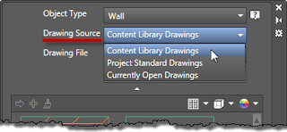
The Drawing Source pull-down offers up to three options for determining the possible drawing sources for styles: Content Library Drawings, Project Standard Drawings or Currently Open Drawings. Content Library files are user-selected files that contain "office standard" styles. These can include the same files you use as source files for your Tool palette tools, and the initial list includes the out-of-the-box style source files. (See below for more on this.) Project Standard Drawings will only be included on the list if you have an ACA Project (Project Browser/Project Navigator) open. As you might expect, Currently Open Drawings will make the styles/definitions in all currently open drawings available.

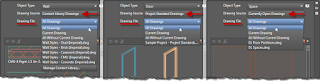
The third pull-down, Drawing File, allows you to further refine the source files used for the styles/definitions that are displayed. The choices here will vary with the Object Type and Drawing Source selected in the first two pull-down lists. The list starts with All Drawings, which will include all of the drawings included in the selected Drawing Source, plus the current drawing. Current Drawing will only show items from the current drawing. All Without Current Drawing will show styles/definitions only from the file(s) from the specified Drawing Source, but will not include those in the current drawing. These three choices will then be followed by the individual file(s) from the specified Drawing Source, allowing you to limit the items shown to just that one drawing.
When using Currently Open Drawings as your Drawing Source and only one drawing file open, selecting All Without Current Drawing in the Drawing File drop-down list will result in an empty style/definition list box, since there are no other drawings open. You can only select one item from the Drawing File dropdown list, so you will not, for example, be able to hold down the CTRL key and choose two individual drawings. Similarly, if Project Standard Drawings is selected as the Drawing Source when Project Standards is disabled for the current Project, choosing All Without Current Drawing in the Drawing File drop-down list will also result in an empty style/definition list box.

The final means of affecting the styles/definitions that are shown in the style list box is the Search Style edit box. Any text entered here is compared to the names of the styles/definitions that meet the criteria of the choices made in the three pull-down lists, and only those that match the string are shown. Any portion of the name may be entered; for example, in the image below, only the Wall Styles that have the text Air-2 somewhere in the style name are shown. The entered text is treated as a wild-card string, with an * before and after the text. You cannot, however, type wildcard characters as part of the search string; all typed characters are interpreted literally.

As previously mentioned, you can customize the drawings included when Content Library Drawings is the selected Drawing Source. To do so, select Content Library Drawings as the Drawing Source, and then select the Drawing File pull-down list. At the bottom of the list, select the Manage Content Library button. This will open the Content Drawings Library dialog, in which you can add or remove drawing files from the list of source files for the Object Type selected in the top drop-down list. Make note of the Save as default toggle in the lower left corner. With this toggle unchecked, you can make "temporary" changes to the list of content drawings by adding and/or removing files and selecting OK. For example, if your current project does not have any Walls with brick components, you could remove the brick Wall source file from the list temporarily. Any "temporary" changes will persist, even after closing and reopening the program. You can, however, restore the saved list by reopening the Content Drawings Library dialog and using the Restore button. If you want to change that saved list, make the desired changes, check the Save as default toggle and then select OK.

Once you have made your selections in the drop-down lists, you may wish to save some of that vertical space in the palette. You can do so by selecting the button with the upward pointing arrowhead icon, bewteen the Search Style edit box and the style/defintion list box. This will leave only the Object Type pull-down list and expand the area available to list box. In the collapsed state, you can make changes to the Object Type selection. If you do so, the Drawing Source and Drawing File choices will remain the same, but any text in the Search Style edit box will be cleared. Select the button again (now with a downward pointing arrowhead), to expand the filter controls if you want to make changes or add text to the Search Style edit box.

The final feature in the top portion of the palette is the Help button (speech bubble icon with ?), which provides direct access to the online help topic on the Styles Browser.

In Part 2, the features associated with the style/definition list box, and the ways of using the Style Browser will be covered.