December 31, 2019

Revit: New Ceiling Grid Pattern, Part 1 - Fill Pattern

In order to have a new ceiling type with a "custom" ceiling grid pattern, you need a Fill Pattern that defines the grid pattern, a Material to which that Fill Pattern can be assigned as a Surface Pattern, and, finally, a Ceiling Type to which that Material can be assigned. While you can start by duplicating a Ceiling Type and drill your way through the various dialogs until you get to the point where you create a new Fill Pattern for the ceiling, and then drill your way back out, I am going to break the process down into three separate steps, so that each step serves as a tutorial for that operation and can be referenced when the need for that operation comes in a different context.

The first step is to create a Fill Pattern that defines the ceiling grid. I am assuming that you have a Fill Pattern file (PAT) that defines a Model type of pattern (as it represents a real-world object, a ceiling grid, that wants to hold the same dimensions, no matter the scale of the view in which it is seen). For the purposes of this example, I am using a custom Fill Pattern that is called Ceiling_4-24x24_1-48x6. It has four rows of 2'-0" x 2'-0" tiles, and then a row of 6" x 4'-0" tiles, as seen in the image below.
Here is how to make that PAT file pattern available in Revit, as a Fill Pattern.
  1. On the Manage ribbon tab, on the Settings panel, select the Additional Settings tool to deploy the menu, and then choose Fill Patterns from the menu.
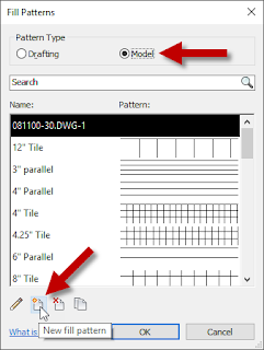
  2. In the Fill Patterns dialog, set the Pattern Type to Model. Then select the New fill pattern tool.
  3. In the Add Surface Pattern dialog, set the Type to Custom. Then select the Browse button.
  4. In the Import Fill Pattern dialog, navigate to the location where you saved the Ceiling_4-24x24_1-48x6.pat file, and select it. Select the Open button.
  5. Back in the Add Surface Pattern dialog, verify that the Name is what you want (it will default to the pattern name) and the Import scale is set to 1.00 (since this is a model pattern, and the pattern was created at full size). Select the OK button to add the Fill Pattern and dismiss the Add Surface Pattern dialog.
    NOTE: This example uses a PAT file that only defines one pattern, so the desired pattern is already selected. If your desired pattern is in a PAT file that defines two or more patterns, then you will need to find and select your pattern in the list box to the left of the Browse button. Revit will only display patterns of the type selected (Model, here), and will sort them in the list alphabetically. The first pattern on the list will be selected initially, but that may not be the one you want. You can use the Search box above the list box to type in part of the pattern name you seek to make it easier to find, if the file contains a lot of Model patterns.
  6. You should see the newly added model pattern in the Fill Patterns dialog. Select the OK button to accept the added pattern and return to the Revit model.

Part 2 will cover creating a Material which will use the newly created Fill Pattern.

November 15, 2019

ACA-AMEP: Edit Property Data Via AutoLISP, Part 3

First article in the series.
Previous article in the series.

In the previous article, we used a while loop to examine each Property Set in the collection of Property Sets attached to the object of interest, comparing each Property Set's Name to the name of the Property Set that holds the Property whose value is to be changed. At this point, there are two possible conditions:
  1. A matching Property Set was found. The value in the Property Set counter variable, iPSet, was set to one more than the number of Property Sets in the collection (variable iPSets).
  2. A matching Property Set was not found. The value in the Property Set counter variable, iPSet, will be equal to the number of Property Sets in the collection (variable iPSets).
(cond    ; Cond A.
  ((= iPSet iPSets)
   ;; If the Property Set is not found after processing all attached property sets, issue prompt.
   (prompt
     (strcat
       "\nProperty Set "
       sPSet
       " not found on object passed to argument obj. "
     ) ;_ End strcat.
   ) ;_ End prompt.
   nil    ; Return nil.
  ) ;_ End condition A1.
  (T    ; Else, continue.
   (setq oProps (vlax-get-property oPSet 'Properties)
          ; Get Properties object of the Property Set.
         iProps (vlax-get-property oProps 'Count)
    ; Get number of Properties in the Property Set.
         iProp  0  ; Initialize Property counter.
   ) ;_ End setq.

   (while (< iProp iProps) ; While unprocessed Properties remain...
     (setq oProp   (vlax-invoke-method oProps 'Item iProp)
    ; Get current Property object.
    sPropNm (vlax-get-property oProp 'Name)
    ; Get Property name.
     ) ;_ End setq.
     (if (= (strcase sPropNm) (strcase sProp))
        ; If target Property found...
       (setq iProp (1+ iProps)) ; ...exit while loop.
       (setq iProp (1+ iProp)) ; ...else, increment Property counter.
     ) ;_ End if.
   ) ;_ End while.

   (cond   ; Cond A2B.
     ((= iProp iProps)
      ;; If the Property is not found after processing all Properties in the Property Set, issue prompt.
      (prompt
        (strcat
          "\nProperty "
          sProp
          " not found in Property Set "
          sPSet
          " attached to the object passed to argument obj. "
        ) ;_ End strcat.
      ) ;_ End prompt.
      nil   ; Return nil.
     ) ;_ End condition A2B1.
     (T    ; Else, update Property value with processed value.
      (setq varPropValOld (vlax-get-property oProp 'Value))

      ***** ADD CODE HERE TO GENERATE THE DESIRED NEW VALUE   *****
      ***** SET VARIABLE sPropValNew to the NEW DESIRED VALUE *****

      (vlax-put-property oProp 'Value sPropValNew)
      sPropValNew   ; Return new string value.
     ) ;_ End condition A2B2.
   ) ;_ End cond A2B.

  ) ;_ End condition A2.
) ;_ End cond A.

Here is what is happening in that code:
  • A cond statement is used to determine which of the two conditions noted above is active. The first test checks to see if iPSet and iPSets are equal. If this is true, then the target Property Set was not found, and there is nothing to process. A prompt is written to the command line to inform the user. I have a separate subroutine to hold this code, so after issuing the prompt, this condition returns nil to the calling routine, to indicate that the requested Property Set was not found. The calling routine can then choose how to handle that situation.
  • If iPSet and iPSets are not equal, then the target Property Set was found and we can continue on. The test for this condition is T (True), because if the first test is false, no further test is required, and the code to process will be contained within this condition.
  • Variable oPSet holds the Property Set object whose name matched the target Property Set name. The Properties property of the Property Set object is used to obtain the Properties collection of that Property Set. The Properties collection contains all of the individual Property objects that are defined in that Property Set Definition.
  • The Count property of the Properties collection is used to determine the total number of Properties in the collection (variable iProps). A variable to hold the Property counter, iProp is initialized to 0, the index of the first Property in the collection.
  • Similar to the way we iterated over the Property Set collection, a while loop is used to iterate over the Properties collection, looking for a Property whose name matches the target property name, which is held in variable sProp. If a match is found, iProp is set to one more than the total number of Properties in the collection. If a match is not found, then iProp is incremented by 1, so that the next Property in the collection will be processed on the next pass of the loop, if at least one unprocessed Proeprty remains.
  • At this point, there are two possible conditions:
    1. A matching Property was found, and the value of iProp is one more than the value of iProps
    2. A matching Property was not found, and the values of iProp and iProps are equal.
  • Once again, a cond statement is used to run the appropriate code. If a matching Property was not found, the first condition writes a prompt to the command line to inform the user that the Property was not found, and returns nil to the calling routine, to indicate that the requested Property was not found in the requested Property Set. The calling routine can then choose how to handle that situation.
  • If the target Property was found, then the first condition will not be executed, and the second condition will be executed, as the test is set to T.
  • The Value property of the Property object is used to obtain the current value, storing it in variable varPropValOld.
  • At this point, you will need to add the code that generates the new value for the target Property, saving that value to variable varPropValNew
  • The vlax-put-property function is used to push the new value onto the Value property of the Property Object. This condition then returns the new value to the calling routine.
  • All of the currently open conditions and cond functions are then ended.

If you choose to have all your code in a single AutoLISP command function, then instead of returning nil or varPropValNew at the end of the A1, A2B1 and A2B2 conditions, you would add whatever additional code you may feel appropriate to run prior to the end of your command function.

November 05, 2019

ACA-AMEP: Edit Property Data Via AutoLISP, Part 2

First article in the series.

In the previous article, we obtained a collection of the Property Sets on the object for which we want to change the value of a Property. We also determined the total number of Property Sets in the collection, and set up a Property Set counter, initialized to 0, the index of the first Property Set. The following code assumes that you know not only the name of the Property that is to be changed, but also the name of the Property Set in which it resides and that the name is stored in a variable called sPSet.
(while (< iPSet iPSets)  ; While unprocessed Property Sets remain...
  (setq oPSet   (vlax-invoke-method oPSets 'Item iPSet) ; Get current Property Set object.
        sPSetNm (vlax-get-property oPSet 'Name)         ; Get Property Set name.
  ) ;_ End setq.
  (if (= (strcase sPSetNm) (strcase sPSet))             ; If target Property Set is found...
    (setq iPSet (1+ iPSets))                            ; ...exit while loop.
    (setq iPSet (1+ iPSet))                             ; ...else, increment Property Set counter.
  ) ;_ End if.
) ;_ End while.

Here is what is happening in that code:
  • A while loop is used to iterate over the Property Sets collection. The Item method is used to get the Property Set at the current index value in iPSet.
  • The Name property of the Property Set object is used to obtain the name of that Property Set.
  • An if statement is used to determine if that Property Set name matches the target Property Set name. The strcase function is used to change both strings to all capital letters, to avoid any issues with different capitalization of the names. If a match is found, the iPSet index counter is set to a number one greater than the total numnber of Property Sets in the collection, so that the loop will be exited. If a match is not found, the iPSet index counter is incremented by 1, so that the next Property Set in the collection will be processed on the next pass of the loop, if at least one unprocessed Property Set remains.

Next article in the series.

November 01, 2019

ACA-AMEP: Edit Property Data Via AutoLISP, Part 1

Sometimes you need to make changes to the values of a Property on all or many AEC Objects in a file. If that change can be done programatically (example, in a text-type manual Property, edit the text value, replacing all occurrences of "1ST" with "2ND"), and there are a large number of Objects to process, it may be easier to do so via AutoLISP, than to manually edit each value. This series of articles will show you how to do so.

NOTE: I have only used this technique on manual Properties. I am not certain what would happen if you tried to use this to change the value of an automatic property. I suspect the change may fail, at least in some cases, like formula Properies. Even if it works for some automatic Properties, such as the height or width of a Door, doing so may have unexpected results in the drawing. If you have a use case for trying to edit the values of automatic Properties, please test this thoroughly on copies of files, or files created strictly for testing purposes, not on actual project files, until you are certain there is no harm.

The VisualLISP commands will be used to access the object model. You will also need to operate on vla-objects. If your method of getting the selection set on which to operate results in AutoLISP entity names, these can be converted to vla-objects by using the
(setq obj (vlax-ename->vla-object ename))
function, where obj is the name of a variable holding the vla-object and ename is the name of a variable holding the entity name of the object on which you want to operate.

Getting to the Property value is not a matter of simply querying the object for it. You will need to drill down into the object model. Start with the following code. You can use different variable names if the ones used in the example code here do not conform to your naming standard. Just make certain you substitute your names consistently.
(vl-load-com)
(setq objAcad    (vlax-get-acad-object)  ; AutoCAD Application Object.
      objAecSchd (vla-GetInterfaceObject objAcad (strcat "AecX.AecScheduleApplication" (aecappver)))
                                         ; AecScheduleApplication object.
      oPSets     (vlax-invoke-method objAecSchd 'PropertySets obj)
                                         ; Get PropertySets collection object.
      iPSets     (vlax-get-property oPSets 'Count)
                                         ; Get number of Property Sets in the PropertySets collection object.
      iPSet  0                           ; Initialize Property Set counter.
) ;_ End setq.

Here is what is happening in that code:
  • The (vl-load-com) function loads the VisualLISP functions, if they are not already loaded. If they are loaded, it does nothing.
  • The first item in the setq function gets the AutoCAD object. This is then used to get the AEC Schedule Application object. This object is version-specific, so I use a subroutine I put together to return the version string, called AECAPPVER. You can find the code for that routine in this previous article. The article was updated to support versions through 2020.
  • The third item in the setq function uses the PropertySets method of the AEC Schedule Application object to get the PropertySets collection for the object on which we want to operate (which is held in the obj variable).
  • The final two items in the setq function determine the number of Property Sets that are in that collection, and initializes a Property Set counter to 0, which is the index of the first Property Set in the collection.

Next article in the series.

October 29, 2019

Dynamo: String Concatenation 2

I had some time and tested some scenarios using the "successful" nodes for concatenating a list of strings shown in this previous post and noticed that the concatenation will still work if the lists do not all have the same numbers of strings. It still concatenates the first item in each list, and so on; once the shortest list runs out of items, it simply does not contribute anything to subsequent concatenations. The process will fail, if the items in the source lists contain anything other than strings, however. That is not a particular surprise (to me, anyway), but a combination of being able to handle non-text items in the source lists without throwing an error/crashing the graph and wanting to see just what it would take to write a Python Script node that could process a variable number of lists of strings prompted me to try it.

A List Create node is still necessary to make a single list of lists to serve as the input, so that the Python Script node need only have one input, but the List.Transpose and List.Flatten nodes can be eliminated.


The Python code is fairly straightforward.
  • The input list of strings is assigned to lstInput, and lstOutput is set up as an empty list, to receive the list of concatenated strings, which will be the output of the node.
  • A for statement examines the length of each of the sublists in lstInput, to determine the maximum list length (maxLength). This is used to set the number of times the concatenation code needs to be run: once for every item in the longest list.
  • An index counter, iIndex, is initialized to the first index, 0.
  • A while statement is used to process the lists, once for each item on the longest list.
  • On each pass through the while code, a variable to hold the concatenated string from that pass (strConcat) is initialized as an empty string.
  • Then, for each sublist in lstInput, strX is set to the string at the current index being processed. This is done in a try statement, so that the code does not fail when a shorter list has no item at the current index. If a value is returned, an if statement verifies that it is a string. If not, strX is reset to an empty string. If a value is not returned to strX, the except statement sets strX to an empty string.
  • The string value in strX is then added to the end of strConcat, and the for statement is rerun for the next sublist, until all sublists have been processed.
  • With the fully processed concatenated string in hand, an if statement checks the value, to see if it remains an empty string. If not, the string is appended to lstOutput. If it is empty, no action is taken.
  • Finally, the index counter (iIndex) is incremented, and the while statement is run again, provided that iIndex remains less than the length of the longest sublist (maxLength).
  • Once the while statement has been run once for each item in the longest list, the list of concatenated strings in lstOutput is sent to the output of the node.
It turns out that the code required to handle a variable number of lists of strings was not as complicated as I thought before I wrote it. For situations where I am certain that the lists of strings to be concatenated will in fact be lists of strings, I probably would use the out-of-the-box nodes shown in the previous article, as it is easier to read (no "magic" black box of Python code doing who knows what), but in cases where the lists might not all be lists of strings (user inputs?), I might choose to use the Python Script node rather than checking the lists of strings to verify that all items are strings.

October 25, 2019

Dynamo: String Concatenation

This may be basic and blindingly obvious to more experienced Dynamo users, but this is something with which I have struggled for some time, and now that I have finally sorted it out, I wanted to document it here for easy future reference.

The String.Concat node in Dynamo provides an easy way to combine two or more strings into one string.
When each item fed into the stringn inputs is an individual string, all of the strings are combined into one string, and that is the output of the node, as shown in the image above.

I rarely need to combine one set of individual strings, however; I almost always have lists of strings to process. Perhaps there is some deficiency in the way I think, but when I first tried to use the String.Concat node with lists of strings, I was expecting that the the result would be a list of concatenated strings, and that the value at each index in that list would be the concatenation of the strings at that same index in each of the input strings. Unfortunately, that is not what the node does.
As you can see, the result is a list of strings, one for each input, with the strings in each input concatenated together. I was expecting ["abc", "123"], but I got ["a1", "b2", "c3"]. This seems contrary to what it does when single strings are input - at least, it does to me. I found this quite frustrating, and on at least one occasion, wrote a quick Python Script node to do the concatenation the way I wanted it. But that quick Python Script did not allow for varying numbers of input lists of strings (I suppose it could be written to do so, but that would no longer be "quick"). I could not understand why the String.Concat node would not do what I wanted, and could not believe that the way it works is what most users would want, most of the time.

Once I set aside my frustration and started thinking again, it dawned on me that all I needed to do was rearrange my input data to work with the way the String.Concat works, and while that requires a few extra nodes, it is fairly easy to do. (Click on the image below to see it full-size.)
By using the List Create node, I combined my individual lists into one list of lists. The List.Transpose node then transforms that list of lists into another list of lists, in which each sublist has a list of the items from the same index in the original sublists. So each sublist has a list of the strings I want combined into one string, and this can be fed into the String.Concat node to get the desired concatenation. The output of the String.Concat node ends up having the list of concatenated strings nested in a list, so adding a List.Flatten node using the default flatten amount (totally flatten) results in a list of the concatenated strings, which was my desired result.

September 11, 2019

ACA: Rotation Property for Multi-View Blocks

Robin Capper made the observation in a post to the AutoCAD Architecture Forum that Multi-View Block References do not have an automatic property for Rotation, unlike Block References or MInsert Blocks. I was surprised to see that was true, but figured that a Formula Property would be able to get the value, if it is exposed.

A quick check using the "vlax" functions in AutoLISP verified that the Rotation property is exposed in the API. I have gotten a little rusty on the specifics of accessing data from the drawing in a Formula Property, but after a few searches of this blog, I had enough to refresh my memory and come up with this as the formula for a Formula Property in a Property Set Definition that applies to Multi-View Block References:
pi = 3.141592653589793238462643383
Set acadApp = GetObject(,"AutoCAD.Application")
Set mvbObj   = acadApp.ActiveDocument.ObjectIDToObject( [ObjectID] )
RESULT = CDbl(mvbObj.Rotation * 180.0 / pi)

Before you create the Formula Property, add an instance of the ObjectID automatic property to the same Property Set Definition. In the formula, [ObjectID] needs to be a reference to that property, created by double clicking on the property in the Insert Property Definitions area of the Formula Property Definition dialog. You cannot just type [ObjectID] in the formula. When the reference is added, it will have a light gray background.

The angle value obtained from the Multi-View Block Reference object is in radians; I chose to convert that value to degrees. If radians will suit your needs better, you can delete the first line and, in the RESULT line, delete * 180.0 / pi. After posting my reply, I came across a better way to generate the value for pi:
pi = 4 * Atn( 1.0 )

August 29, 2019

Revit: Yes/No Parameter Values

You might think that a Yes/No parameter can only have two values:
  • Yes
  • No
But, in fact, there can be three values:
  • Null
  • Yes
  • No
Null will only occur when a Yes/No parameter is first placed on an object, such as when you add an instance-based Yes/No Project Parameter to one or more categories in your project (for this example, Walls). After doing so, you will see something similar to this:
In the image above, the HasToggle Yes/No parameter has just been added to Walls. The toggle itself (the square in the value column) shows a check mark, but the check mark and the square are grayed out. You might think this means that the parameter is disabled, but if you look at the parameter name, it is not grayed out. Contrast this to the Enable Analytical Model parameter a few rows below the HasToggle parameter, where both the parameter name and the square are grayed out. The Enable Analytical Model parameter is disabled, because the Structural parameter (another Yes/No parameter) is not checked. The HasToggle parameter is enabled, but the toggle is grayed out to indicate that a value for the parameter has not yet been chosen, so the value is at its initial "Null" state.

Left clicking on the toggle will set the value to Yes, and the toggle is no longer grayed out.

Left clicking on the toggle again will change the value to No.

Once the toggle is clicked and an initial value set, you cannot set it back to Null, so, in operation, there are only two values, Yes and No, but you need to be aware that parameter can have that third value, Null, as that can have an impact on your model. For example, suppose the HasToggle parameter is used to drive two filters, that will be used to change the display of Walls in a view.
In the image above, you can see that two filters have been created, HasToggle-Yes and HasToggle-No, along with the properties of the HasToggle-Yes filter. The filter applies to Walls, and will select all Walls where the HasToggle parameter is set to Yes. The HasToggle-No filter properties are identical, except the filter collects Walls whose HasToggle parameter value is set to No. In the LEVEL 1 FLOOR PLAN View, these filters have been applied and an unattractive combination of colors has been assigned to the Cut Lines and Patterns, to make it obvious that the filter has been applied.

In the image below, you can see eight Walls in the LEVEL 1 FLOOR PLAN View. Two have had the HasToggle parameter set to Yes (checked), two have had the HasToggle set to No (unchecked) and the other four remain in the initial Null state. The Null Walls are not affected by either filter, because the value of the HasToggle parameter is neither Yes nor No.

August 27, 2019

AEC Answer Day - September 24, 2019


Another installment of Autodesk Answer Day, focused on AEC-related products, will take place in the the following forums:
  • English-language Users, 6:00 am (September 24) to 2:00 am (September 25) Pacific Standard Time
    • AutoCAD
    • Civil 3D
    • Revit
    • BIM 360
  • German-language Users, 9:00 am to 5:00 pm Central Europe Time (September 24)
    • AutoCAD Produktfamile - Deutsch
    • Revit - Deutsch
    • Inventor - Deutsch
    • Fusion 360 - Deutsch
    • EAGLE - Deutsch
    • PowerMill, PowerShape, PowerInspect & FeatureCAM - Deutsch
    • BIM 360 - Deutsch
    • 3DS Max - Deutsch
    • Maya - Deutsch forums.

More information, and links to the forums noted above, can be found in this Community Announcement. Stop in that day with your questions and interact with the Autodesk staff that will be taking part.

August 01, 2019

ACA: Got Blips?

Many younger users may have never seen "BLIPS" and many older users have probably forgotten about them. The BLIPMODE command and System Variable have been undefined in AutoCAD® and its verticals since the 2012 release. Back in the day, if BLIPMODE was turned on, every pick would be memorialized on screen with a small, white "+" mark. ZOOMing, PANning or using the REDRAW (yes, that command did have a function once) or REGEN commands would clear these temporary markers from the screen. But if you worked for a while without needing to change your view, you could accumulate a lot of these (and would probably quickly turn BLIPMODE off).

Undefined is not the same as removed, however, and the command is still there, and the System Variable can be accessed via AutoLISP. The System Variable was (is) stored in the Windows Registry, not in the drawing file, so someone could change the setting in the registry, as well. If you find yourself working in a drawing and having blips show up with each left mouse click, even if you remember "BLIPMODE," you will find that neither the command nor the System Variable is "known" by recent versions.

What to do? At the command line, type in the command with a period at the front: .BLIPMODE. The period tells AutoCAD to use the original definition of the command, and suddenly AutoCAD recoginzes it.

Press the ENTER key, and then choose OFF from the command line options.

Or, if there is someone in your office who is overdue for a (mostly) harmless prank, wait for her/him to leave her/his workstation with AutoCAD open. Start a new drawing, type .BLIPMODE, press ENTER and choose ON. Close the new drawing without saving. Discretely slip away, and await your colleague's return, and eventual annoyance. You may want to pop in and offer to fix the issue, before things escalate to an HR-level event. [Use at your own risk.]

July 13, 2019

AUGI Salary Survey, 2019

Help make the survey results more accurate by taking the survey and adding your information: 2019 AUGI Salary Survey.

July 11, 2019

ACA: Schedule Tag Background Mask

I suppose I must have known about this at some time in the past, but having never made use of it, it slipped my mind. The other day, I needed to make some Schedule Tags to replace some attributed Block References. The Attribute Definitions in the Block References had background masking turned on, so that they could be placed on top of other linework and the mask would assure that the contents of the attribute remained readable.

I made use of the graphics from the Block Reference and ran it through the DefineTag command to create the Schedule Tag Multi-View Block reference. I was hoping that the background mask on the Attribute Definition would be respected in the Schedule Tag, but it was not. An internet search turned up this Autodesk Knowledge Network Article, allowing me to re-learn what I had probably forgotten. You create an AEC Polygon Style to use for the background mask; on the Other tab, check the Use Background Mask toggle.

If you do not want the border of the AEC Polygon to plot, go to the Display Properties tab and create a Style Override for the Model Display Representation. In the override, turn off the visibility of the Exterior Edge component. (Do the same for the Model Screened Display Representation if you use that in views that include the Schedule Tags.)

Place an AEC Polygon instance using the Style you just created as part of the graphics you select for the DefineTag command. Be sure to select the AEC Polygon first, and then the other graphics, so that the other graphics are not masked by the AEC Polygon.

In the image below, the Door Tags have had a masking AEC Polygon placed behind the other graphics, and that AEC Polygon is masking out the color fill of the Space and the swing of the Door that is behind the Tag.

July 03, 2019

ACA: Open Dialog Does Not Show - But FILEDIA Is Set to 1

I had a report that the AutoCAD® Architecture Open dialog was not showing up when the OPEN commmand was being used. First thing I checked was the value of the FILEDIA System Variable, but it was set to 1, and there were no prompts on the Command Line when running the OPEN command.

I found the solution for this case in an Autodesk Knowledge Network article, Dialog windows do not display and the program appears to freeze, which offers several suggestions for resolving the issue. Having already done the first one (FILEDIA), I tried the second one - holding SHIFT+WINDOWS KEY and then pressing the LEFT or RIGHT ARROW KEY. That keystroke combination moves the current window from one screen to the next, and it did bring the Open dialog back onto one of the two active monitors.

The user's computer is a laptop, which was docked and closed, but perhaps the dialog was hiding out on the laptop monitor? Wherever it was, the issue was resolved, and I was glad to not have to resort to the last suggestion, editing the Windows Registry.

June 26, 2019

Revit: Phasing Area Plans

We use Area Plans in Revit to assist in calculating the occupant load on our life safety drawings. A recent project was being done in phases, and separate life safety plans were required for each phase, showing the occupant load (and egress) at the end of each phase. Area Plan Views do have Phase and Phase Filter parameters (to show the modeled elements correctly for a given plan), but Area objects do not have Phase Created and Phase Demolished parameters, so their visibility cannot be controlled by the phase settings on an Area Plan View.

Phased Area Plans can be created - but you need to make a separate Area Scheme for each separate phase to be shown. Here is how to do that:
  1. On the Architecture ribbon tab, on the Room & Area panel, select the panel title to deploy the flyout and then select the Area and Volume Computations tool.
  2. In the Area and Volume Computations dialog, select the Area Schemes tab and then select the New button.
  3. Give the new Area Scheme a name and description, clearly identifying the phase to which it will apply in the name. Create additional Area Schemes, one for each phase needed.
  4. Select the OK button to create the new Area Schemes and dismiss the dialog.
  5. On the Architecture ribbon tab, on the Room & Area panel, select the Area tool. On the flyout, select the Area Plan tool.
  6. In the New Area Plan dialog, set the Type to one of the "phased" Area Schemes you just created, and then select the Level(s) for which you will need plans for that "phase".
  7. Repeat the creation of Area Plans for the other "phased" Area Schemes.
  8. In the Project Browser, select one of the Area Plan Views you just created and, in the Properties palette, set the appropriate values for the Phase and Phase Filter properties, so that the plan view of the model shows correctly for that phase. If you have (a) View Template(s) set up for these Area Plans, apply the appropriate template. (If the template controls the Phase Filter, you can skip setting that in the Properties palette.)
You now have Area Plans for each phase. Add the desired Areas to each. Each Area Scheme is independent of the others, so any Areas that are common to two or more Schemes will have to be created in each.

One other note, if you need to create Schedules for the Areas, be aware that you have to specify the Area Scheme to which the Schedule applies at the time of Schedule creation, and you cannot change that later. What that means is if you have multiple Area Schemes, and need the same Schedule for each Scheme, you will not be able to create one, duplicate it and then change the Scheme to which it applies. You will need to create a Schedule for each Area Scheme from scratch. (If you need multiple Schedules of the same type within one Area Scheme - for example, if you have separate Schedules for the occupant loading of each level - you can duplicate the first schedule created for that Area Scheme, and then change the filtering to show different items (such as from another level).

May 08, 2019

ACA: ExportToAutoCAD - Room Tag Attributes Not Shown

I came across something curious today. Someone wanted to link an AutoCAD® Architecture drawing in Revit, but the Room Tags were not showing. That is because Revit cannot read AEC Objects (not the curious thing). I suggested using one of the EXPORTTOAUTOCAD commands to create a copy of the file, with all of the AEC Objects exploded to AutoCAD linework. That was done, but in the resulting file, the blocks that were the result of exploding the Room Tags were not showing any of the attributes that should have been displaying the room name and number.

Here is the curious part: Grips for the "missing" attributes displayed, and, in the Properties palette, values for the room name and number attributes were shown.

I tried REGENerating the drawing, I checked layers 0 and Defpoints to verify they were on and thawed and even tried an OBJRELUPDATE (even though the object was now an AutoCAD block, and not an AutoCAD Architecture Multi-View Block). I inserted a new instance of the block, and values entered into the room name and room number attributes displayed as expected. Fortunately, lunch intervened, allowing my frustration to subside. With a semi-fresh brain, I returned to the issue after lunch, and it occurred to me to try running ATTSYNC on the block. And that turned out to be the solution, as the values displayed after doing so.

I was not able to reproduce this in a sample file, created with the same content, but at least I have a solution should I come across this again in the future.

April 11, 2019

Dynamo: Python Node to Test For Presence of a Parameter on an Object

We have a Dynamo graph that allows the user to search for a user-specified string in the names of Views and, if found, replace it with a second user-specified string. This comes in handy when someone decides that all of the instances of "LEVEL" in the view names should be changed to "FLOOR". The graph worked, but would result in an error condition, because there are, apparently, Views that do not have a "View Name" parameter attached to them. Attempting to retrieve the View Name parameter value from all elements of the Views category using an Element.GetParameterValueByName node resulted in this error:

While this did not appear to interrupt the processing of all Views, I would prefer to not have an error reporting (in both Dynamo and Dynamo Player), so that I do not have to explain to others who might use the graph that having that error is "Ok". I thought it would be simple to construct a BoolMask to filter out the Views without a View Name parameter, and proceeded to try to do so. Perhaps there is an easy way to create that BoolMask with core nodes or with something from a package, but my initial attempts were unsuccessful. The best I could do was get a list with true for the Views with the parameter but null for the Views without it, while throwing additional errors; that result also did not work as a mask in the List.FilterByBoolMask node. I quickly ran out of patience and decided to generate the mask list using a Python node, which turned out to be fairly easy.

Each Element in the Revit Model has a ParametersMap attribute, which is a map that contains all of the parameters the Element contains, accessible via the parameter Name, using the Contains(key) method for the ParameterMap object, where the key is the name of the parameter of interest. The potential for an error condition for Views without a View Name parameter can be handled by using try: and except: statements to build the mask list, as shown in the image below.

The Python node has two inputs, the first, IN[0], a list of Elements to be tested for the presence of a particular parameter, and the second, IN[1], a string representing the name of the parameter. The Contains method will return True if the Element's ParametersMap contains a parameter whose name matches the string passed to the Python node in IN[1]. If there is not a matching parameter name, it should return False; in testing, some of the Views were throwing an error, in which case the except: statement adds False to the output list.

The output from this Python node worked to remove the Views without a View Name parameter from the list of all elements of the Views category, allowing the rest of the graph to do the renaming of the Views without any error messages.

April 05, 2019

ACA: Import Layer Standard

If you have a custom Layer Key Style that is built on a custom Layer Standard, best practice is to establish a source file for Layer Standards and Layer Key Styles, such as the out-of-the-box AecLayerStd.dwg, that includes your customizations. Then, using the AECDWGSETUP command to open the Drawing Setup dialog, on the Layering tab you can specify that file as the source file for auto-importing your Layer Standard and Layer Key Style and also specify your Layer Key Style in the Default Layer Standard area.

If you save that as your default, it should get your Layer Key Style and Layer Standard into a drawing file. But if you have multiple Layer Standards, or have not set that up, it is important to note that while you can use the Style Manager to copy a Layer Key Style from one drawing to another, doing so does not bring the Layer Standard on which that Layer Key Style is based along for the ride. Without the Layer Standard, Layer Key Overrides will not work (assuming that your Layer Standard is set up with multiple descriptive fields supporting overrides). Here is how to copy a Layer Standard from an external file to the current drawing file.
  1. In the Layer Properties Manager, select the Layer Standard tool, located at the far right side of the tool bar at the top of the palette. The Layer Standards dialog will open.
  2. In the Layer Standards dialog, select the Import/Export button. The Import/Export Layer Standards dialog will appear. On the left side of the dialog, the Current Drawing's Layer Standard(s) will be listed. On the right side, the Layer Standards of an External Drawing will be shown, if one had previously been selected. If not, it will be blank, as in the image below.
  3. If you have an External Drawing selected, and it contains the Layer Standard you want to import, you can skip to Step #4. Otherwise, use the Open button to open a file dialog in which you can navigate to a drawing file that has the Layer Standard you wish to import. Select that drawing file and select the Open button in the file dialog to return to the Import/Export Layer Standards dialog with the desired External Drawing file in place. Or, if the Recent Files drop-down list has any drawings listed, and if one of those has the desired Layer Standard, you can select it from the drop-down list, rather than using the Open button.
  4. In the External Drawing list box on the right side of the dialog, select the Layer Standard(s) you want to import. Then select the <<< Import button to import it/them from the External File to the Current Drawing. The name(s) of the Layer Standard(s) selected should appear in the Current Drawing list box.
  5. Select the OK button in the Import/Export Layer Standards dialog to accept the change. The imported Layer Standard name(s) will be shown in the Layer Standards dialog. Select the OK button to confirm the change, dismiss the Layer Standard dialog and return to the drawing.

March 14, 2019

ACA: Suppress Multiple Objects Contextual Ribbon Tab

Someone in my office today asked if the Multiple Objects contextual ribbon tab could be suppressed. That is the tab that displays when you select items of different object types.
The individual did not want to have to go back to the tab that was previously active where the tool to be used resided. I recalled that some years back, there were controls that would allow you to not have the ribbon focus shift to the contextual ribbon tab (it would activate, but not become the current tab), to have it show on a single-click or to have it show on a double-click. Those choices are no longer available.

What remains is the ability to set the maximum number of objects for which a contextual ribbon will display (RIBBONCONTEXTSELLIM System Variable). The allowable range is 0 to 32767, with an initial default value of 2500. The purpose of this is to limit performance issues when trying to act on a large number of objects. When the number of objects selected exceeds the current value of RIBBONCONTEXTSELLIM, then a contextual ribbon tab will not display, and any ribbon property controls will be disabled (grayed out). Setting the value to 0 allows an unlimited number of objects to be selected and still get a contextual ribbon tab, so this cannot be used to turn off contextual ribbon tabs. But setting it to 1 will allow contextual ribbon tabs to display when just one object is selected (which most would find desirable, particularly for AutoCAD® Architecture and AutoCAD® MEP objects), but disable it when more than one object is selected. This effectively suppresses the display of the Multiple Objects contextual ribbon tab, but does also suppress all other contextual ribbon tabs when multiple objects are selected. For example, if you select two or more Walls, the Wall contextual ribbon tab will not display.

In addition to typing RIBBONCONTEXTSELLIM at the command prompt, pressing the ENTER key and then typing 1 and pressing the ENTER key, you can also set this value in the Options dialog, on the Selection tab, in the Ribbon options area by selecting the Contextual Tab States button and then editing the value in the Object selection maximum for contextual tab display edit box.

This value is stored in the User Settings (registry) for a given AutoCAD Profile, so setting it once will apply to all drawings you open.

I personally leave the setting at the default 2500, but if you often select multiple objects of different types with the intent to select a tool on the ribbon that is not on the Multiple Objects ribbon tab and want to avoid having to perform an extra click to get back to where you previously were in the ribbon, then setting RIBBONCONTEXTSELLIM to 1 may improve your workflow.

February 28, 2019

ACA: Custom Display Block for Door in Plan View

You may have noticed that even after assigning a custom Profile to a Door to add a glazed panel to the Door, that there is no change to the graphics when viewing the Door in "plan" (Top view direction) in any of the out-of-the-box Display Representation Sets, That is because these use one of the "plan" Display Representations for Doors (Plan, Plan High Detail, Plan Low Detail, Plan Screened, Reflected or Reflected Screened), and the Panel component in these is 2D graphics representing the panel width and depth (overall Door width only, in Plan Low Detail) that is not tied to the 3D representation where the glazing is shown.

In my work, I have never needed to indicate glazing in a Door Panel at the typical scales used for plan views (1/16" = 1'-0" to 1/4" = 1'-0"). But if you do have a need for that, you can use a custom display block to add graphics to represent a glazed panel in plan views.

Before we dive into creating the block and assigning it to the Door Style, you need to understand the limitations of custom display blocks in plan Display Representations. The only component to which you can assign a custom display block in plan is the Frame component. You cannot assign one to the Panel component. That means you cannot scale the block by the thickness of the Panel, nor will the block rotate to match the swing angle of the Panel. If you use multiple swing angles for your Panels, you will need multiple display blocks and multiple Door Styles (one of each for each angle). For a 90-degree Panel swing angle (the one we typically use for new construction Doors), scaling the custom display block by the Width, even with the Frame Component set to Inside, will not scale the block along the width of the Panel, but perpendicular to the width of the panel (because ACA thinks it is a Frame component). All of this means that if the graphics in the file need to be accurately shown, and not just a "symbol", you will need a separate custom block and a separate Door Style for each Door width.

If all of that did not change your mind about showing a glazed panel in plan views for Doors, here is how to do it.
  1. Identify the Door Style that is to receive the custom display block. For this example, I have a style called Wood Door with Glazing that has a custom Profile assigned as the Shape on the Design Rules tab of the Door Style. That creates a glazed panel in a model view, but has no effect on the plan view graphics, as seen in the image below.
  2. Verify that the target Display Representation for Doors is active in the current Display Configuration. In this example, the custom display block will be attached to the Plan Display Representation for Doors, and that is active in my current Display Configuation.
  3. Place an instance of the Door in the drawing, and set the Width property of the Door to the width intended for the display block. Having an instance in the drawing is helpful for seeing the effects of the editing so far, and, in cases like this where no scaling will be applied to the block, can be used when generating the linework for the block definition.
  4. Determine where the insertion point of the custom display block will be. In this case, the hinge-side corner of the frame (where it meets the corner of the Door Panel) is an appropriate insertion point.
  5. Draw the linework for the custom display block. If you want to be able to control the display of the linework in the display properties of the Door Style, draw the linework on Layer 0, and assign ByBlock to the Color, Linetype, Plot Style (if using named plot styles), Lineweight and Transparency properties of the linework. In this example, the linework consists of two lines perpendicular to the width of the Door Panel, set in 10" from each end of the Door Panel, and a third line connecting the midpoints of the first two lines, to give a symbolic representation of the glass panel in the Door.
  6. Create the block definition from the linework, being careful to specify the desired insertion point. If you choose to retain the linework or convert the linework to a block, move the linework or block to the side, so that it will not obscure the results of adding the custom block to the Door Style.
  7. Select the Door and, on the Door contextual ribbon tab, on the General panel, select the Edit Style tool. (Or, if you prefer, open the Style Manager, navigate to and select the Door Style in the left pane so that you can edit the style in the right pane.)
  8. Choose the Display Properties tab. The currently active Display Representations will be displayed in bold type. In this example, both the Plan and Threshold Plan Display Representations are active. As the Threshold Plan Display Representation does not allow for attaching custom display blocks, the Plan Display Representation will be used.
  9. Select the Display Representation to receive the custom display block. Left click the toggle in the Style Override column for that Display Representation, to add a display override and open the override for editing.
  10. In the Display Properties dialog, select the Other tab. In the Custom Block Display area, select the Add button.
  11. In the Custom Block dialog, select the Select Block button. Choose the block you created in the Select a Block dialog and select the OK button to return to the Custom Block dialog. The block should show in the viewer.
  12. Back in the Custom Block dialog, change the Insertion Point Y: value to Back and set the Frame Component to Inside. When I did this, the block shifted when I changed the Y setting of the Insertion Point, but did not move when I changed the Frame Component to Inside.
  13. I chose to let the Display setting at Always. If you want to limit the situations where the block will display, select one of the other options: When Intersecting Cut Plane, When Above Cut Plane or When Below Cut Plane, and the block will only display when the selected option is true.
  14. Select OK to ratify the changes, close the Custom Block dialog and return to the Door Style Properties dialog.
  15. If you are a bit leery about the fact that the viewer was showing the custom block outside of the Door Panel, you can select the block name that now shows in the list box in the Custom Block Display area and choose the Edit button. That will reopen the Custom Block dialog and the viewer will properly update and show the block inside the Door Panel, where it belongs. If you are not making any changes, you can select the Cancel button to dismiss the Custom Block dialog; otherwise select the OK button after you are finished with any changes.
  16. In the Display Properties dialog, select the Layer/Color/Linetype tab. Notice that the custom display block now appears as a Display Component. You can make any edits here that you desire. I chose to let the default settings (Layer 0, with ByBlock properties), so that the block will inherit its properties from the parent Door object, just like the Panel, Frame and Swing components. You may want something different. Keep in mind these settings will only be apparent if the linework within the custom display block is on Layer 0 with ByBlock properties, as previously noted.
  17. When you are done editing the properties of the custom display block component, select the OK button to return to the Door Style Properties dialog. Notice that there is now a check mark in the Style Override column and that the Display Property Source now shows Door Style Override - [YOUR DOOR STYLE NAME HERE] rather than Drawing Default. Select the OK button to accept all of the changes to the Door Style and return to the drawing.
    NOTE: If you ever need to edit the display settings for this Door Style's Plan Display Representation, select it and choose the Edit Display Properties button in the upper left of the dialog. Do NOT select the Style Override toggle again; that will clear the toggle and remove the override. If you do that unintentionally, select the Cancel button to exit the dilaog without making any changes, or you will have to recreate the override.
The instance of the Door Style in the drawing should now reflect the addition of the custom display block (assuming that you edited an active Display Representation, as directed above). In the image below, the custom display block instance is at the left and selected, and the Door instance, now showning the custom display block, is at the right.