I have looked into rounding in Autodesk Architectural Desktop's Property Data Formats a little further. One quick note first, the property showing the rounding technique mentioned in my previous blog post is the Occupants property in the OccupantLoadStyles Property Set Definition. I should have included that in the previous post.
Rounding up and rounding down also do not work in ADT 2004. I took some time at lunch today to set up a sample file that demonstrates this, and attached it to a new reply in the same thread that has the occupant calculation sample. The post there describes the sample file in detail; a schedule table in the file shows the effect [or lack thereof] of selecting Up, Down or Nearest for the rounding method in a Property Data Format. There is also a property that demonstrates the use of the VBScript Round function, which allows you to round a real number to a specified number of decimal places - nearest only, and "5" rounds up for odd numbers and down for even numbers.
August 31, 2005
Rounding Up Property Data Values
I have found that the "up" and "down" rounding options in Property Data Formats in Autodesk Architectural Desktop 2006 are not working properly. There are situations, such as calculating occupant loads, where you want to round any fractional amount up to the next whole number. The "up" option should do that, but does not.
In my August 30, 2005 post to the "area schedules divided by code area" thread in the Autodesk Architectural Desktop 2006 Discussion Group, I posted a sample file that contains a formula property that forces a round up to the next whole number value. The formula determines the whole number portion of the number to be rounded by using the VBScript Fix function to truncate any fractional part. The whole number is then subtracted from the original number to determine the fractional part. If the fractional part is greater than zero, the RESULT is the whole number plus one; otherwise the RESULT is the whole number.
Note that this assumes that the original number is not a negative value; if the original number is a negative value, you will need to determine which way you want the negative number to go [toward or away from zero] and you would want apply the VBScript Abs function to the fractional value when checking if it is greater than zero.
August 16, 2005
Doug Bowers On Repositioning Doors
Doug Bowers has posted an informative PDF file explaining how to reposition a door both along and within a wall. This PDF applies to Autodesk Architectural Desktop, releases 2004 and newer. Check it out in the ADT 2006 Discussion Group.
August 08, 2005
Beau Turner on ADT Project Navigator
Beau Turner has posted an article with an excellent overview of the Project Navigator in Autodesk Architectural Desktop. If you have considered making use of the Drawing Management features but have not yet taken the plunge, check out this article and dive in.
August 07, 2005
Modifying an Out-of-the-box Wall Style and Endcap
In response to a thread in the Autodesk Architectural Desktop 2006 Discussion Group, I posted a sample file and explanation of one way to take one of the out-of-the-box wall styles that has an endcap, and modify both the wall style and create a new endcap for the modified style. The example shows converting a wall style with 5/8" GWB on a metal stud to 1/2" GWB on the same metal stud.
The original poster managed to resolve his problem using in-place editing; my post explains how to use the WallEndcap command to generate the defining polylines of an existing Wall Endcap Style, then use those to create a new Wall Endcap Style for the modified wall style.
The original poster managed to resolve his problem using in-place editing; my post explains how to use the WallEndcap command to generate the defining polylines of an existing Wall Endcap Style, then use those to create a new Wall Endcap Style for the modified wall style.
August 03, 2005
Schedule Column Loss in "Old" Drawings
Just a quick reminder, prompted by me running into this issue face-first today. If you have an "older" drawing that has a previous version of a Property Set Definition using the same name as your current version, but that may be missing a property or two [or may use a now changed name for the property] that is used for a column in a Schedule Table Style, when you add the current Schedule Table Style to the file, it will not import the current version of the Property Set Definition, as it already exists in the drawing. All columns that reference properties that are missing, or going by an old name, will magically disappear from the Schedule Table Style.
Use Style Manager to manually update the old Property Set Definitions first, then bring in the Schedule Table Style, to avoid column loss. Those using ADT 2006 could make use of the new Standards features to update older drawings that are made part of a project.
Use Style Manager to manually update the old Property Set Definitions first, then bring in the Schedule Table Style, to avoid column loss. Those using ADT 2006 could make use of the new Standards features to update older drawings that are made part of a project.
August 01, 2005
Door/Window Assembly With Half-Height Sidelight
In a post to the AUGI ADT General Forum, I attached a sample file that demonstrates how you can create a Door/Window Assembly that has a Door with a "half-height" sidelight adjacent to it - that is, the top of the sidelight frame aligns with the top of the door frame, but the sidelight does not continue all of the way to the floor.
I started out by copying the out-of-the-box Hinged - Single door style, renaming the copy to Hinged - Single - NoFrame and setting the frame width to 0", to create a frameless door style for use as an infill in a Door/Window Assembly. Then I created a new Door/Window Assembly style called Door - Half-Height Sidelight and set up the following elements:
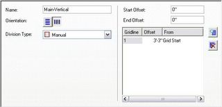
Main-Vertical Division
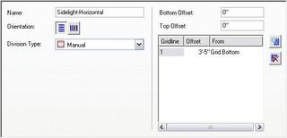
Sidelight-Horizontal Division
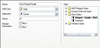
Door-Hinged-Single Infill
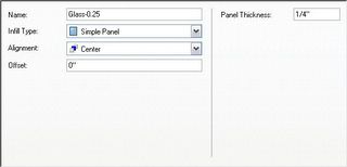
Glass-0.25 Infill
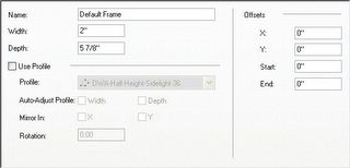
Default Frame Frame
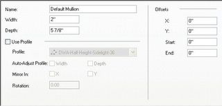
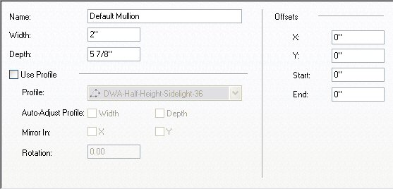
Default Mullion Mullion
The out-of-the-box Doors & Windows.Glazing.Glass.Clear material was assigned to the Glass-0.25 Infill; the Default Frame and Default Mullion components had the Doors & Windows.Metal Doors & Frames.Aluminum Frame.Annodized.Dark Bronze.Satin material assigned [mostly because it came in with the Hinged - Single Door, which has the Doors & Windows.Wood Doors.Ash material assigned to the door panel].
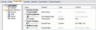
I renamed the Primary Grid to Door-Sidlight, managing to omit the "e" in "Sidelight" in my haste. The assignments for this grid are shown below. Note that a nested grid is assigned to the End cell. This "New Nested Grid" was renamed Sidelight [and spelled correctly, this time]. Also note that Default Frame is only assigned to the left, right and top - the bottom frame is omitted, as we do not want one at the door and the sidelight does not extend to the floor.
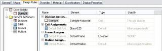
The Sidelight Grid assignments were made as shown below.
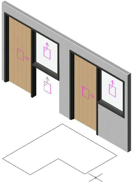
A 6'-6" wide x 7'-2" high instance of this Door Window Assembly style was inserted in an out-of-the-box Stud-3.625 GWB-0.625 Each Side wall. I changed to a SE Isometric view and turned on the infill markers by selecting the Door/Window Assembly, right clicking and choosing Infill>Show Markers from the context menu. With the Door/Window Assembly still selected, I right clicked and chose Infill>Override Assignment... from the context menu, and then selected the infill marker in the lower half of the sidelight cell. I chose the Remove Infill and Frames option in the Infill Assignment Override dialog and selected OK. I then transferred the Design Rules to the object [select Door/Window Assembly, right click, choose Design Rules>Transfer to Object] and then transferred them back to the style [with Door/Window Assembly still selected, right click, choose Design Rules>Save to Style... and then check Transfer Infill Overrides to Style in the Save Changes dialog and click OK]. These overrides are now part of this style and will be applied to all instances of this style. This style is illustrated on the left side of the image below. Notice that even though the bottom cell of the sidelight and its frame are turned off, the wall does not fill in below the sidelight. If you are only interested in a plan view of this assembly, you are essentially done [depending upon the cut plane height and the height at which you set the bottom mullion of the sidelight, you may need to add a manual cut plane to see the mullion]. But if you want to generate an elevation or do a 3D view/rendering, you will need to do one more thing to get the results shown on the right Door Window Assembly.

SE Isometric View ;
In order to get the wall to fill in under the sidelight, you will need to create a profile that describes the outline of the outer edge of the frames/mullions and the floor line, then assign it to the style. Draw a LWPOLYLINE in the desired shape. In the Style Manager, create a new Profile [under Multi-Purpose Objects], give it the desired name, then right click the profile name and choose Set From... on the context menu. Select the polyline and choose an insertion point; I chose the lower left corner [door side]. Note that assigning a profile will effectively fix the dimension of the Door/Window Assembly. You can change the width, and the profile will be scaled to match, but you will get undesirable 3D results - as the width is made less than that used when drawing the profile, the door mullion below the sidelight will start to disappear, and eventually the door will also be notched. As the width grows larger than the original profile width, the wall infill will fall short of the door mullion below the sidelight. In the sample file, I created a copy of the original style, then assigned the 6'-6" wide profile to it. This would allow me to make additional copies of the original style and assign profiles with different widths, if needed.
I started out by copying the out-of-the-box Hinged - Single door style, renaming the copy to Hinged - Single - NoFrame and setting the frame width to 0", to create a frameless door style for use as an infill in a Door/Window Assembly. Then I created a new Door/Window Assembly style called Door - Half-Height Sidelight and set up the following elements:
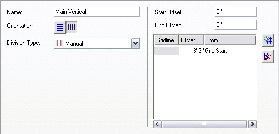
Main-Vertical Division

Sidelight-Horizontal Division
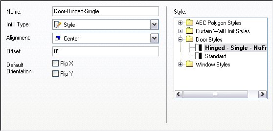
Door-Hinged-Single Infill
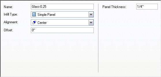
Glass-0.25 Infill
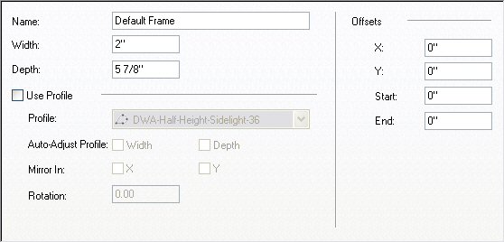
Default Frame Frame
Default Mullion Mullion
The out-of-the-box Doors & Windows.Glazing.Glass.Clear material was assigned to the Glass-0.25 Infill; the Default Frame and Default Mullion components had the Doors & Windows.Metal Doors & Frames.Aluminum Frame.Annodized.Dark Bronze.Satin material assigned [mostly because it came in with the Hinged - Single Door, which has the Doors & Windows.Wood Doors.Ash material assigned to the door panel].
I renamed the Primary Grid to Door-Sidlight, managing to omit the "e" in "Sidelight" in my haste. The assignments for this grid are shown below. Note that a nested grid is assigned to the End cell. This "New Nested Grid" was renamed Sidelight [and spelled correctly, this time]. Also note that Default Frame is only assigned to the left, right and top - the bottom frame is omitted, as we do not want one at the door and the sidelight does not extend to the floor.

The Sidelight Grid assignments were made as shown below.

A 6'-6" wide x 7'-2" high instance of this Door Window Assembly style was inserted in an out-of-the-box Stud-3.625 GWB-0.625 Each Side wall. I changed to a SE Isometric view and turned on the infill markers by selecting the Door/Window Assembly, right clicking and choosing Infill>Show Markers from the context menu. With the Door/Window Assembly still selected, I right clicked and chose Infill>Override Assignment... from the context menu, and then selected the infill marker in the lower half of the sidelight cell. I chose the Remove Infill and Frames option in the Infill Assignment Override dialog and selected OK. I then transferred the Design Rules to the object [select Door/Window Assembly, right click, choose Design Rules>Transfer to Object] and then transferred them back to the style [with Door/Window Assembly still selected, right click, choose Design Rules>Save to Style... and then check Transfer Infill Overrides to Style in the Save Changes dialog and click OK]. These overrides are now part of this style and will be applied to all instances of this style. This style is illustrated on the left side of the image below. Notice that even though the bottom cell of the sidelight and its frame are turned off, the wall does not fill in below the sidelight. If you are only interested in a plan view of this assembly, you are essentially done [depending upon the cut plane height and the height at which you set the bottom mullion of the sidelight, you may need to add a manual cut plane to see the mullion]. But if you want to generate an elevation or do a 3D view/rendering, you will need to do one more thing to get the results shown on the right Door Window Assembly.
SE Isometric View ;
In order to get the wall to fill in under the sidelight, you will need to create a profile that describes the outline of the outer edge of the frames/mullions and the floor line, then assign it to the style. Draw a LWPOLYLINE in the desired shape. In the Style Manager, create a new Profile [under Multi-Purpose Objects], give it the desired name, then right click the profile name and choose Set From... on the context menu. Select the polyline and choose an insertion point; I chose the lower left corner [door side]. Note that assigning a profile will effectively fix the dimension of the Door/Window Assembly. You can change the width, and the profile will be scaled to match, but you will get undesirable 3D results - as the width is made less than that used when drawing the profile, the door mullion below the sidelight will start to disappear, and eventually the door will also be notched. As the width grows larger than the original profile width, the wall infill will fall short of the door mullion below the sidelight. In the sample file, I created a copy of the original style, then assigned the 6'-6" wide profile to it. This would allow me to make additional copies of the original style and assign profiles with different widths, if needed.
AUGI ATP Courses for August 2005
There are three classes this month, starting on August 8. Pre-registration has been re-instituted, so you can sign up for classes today. If you are already an AUGI member, login to the website, click on Education in the link bar below the logo and follow the ATP links at the left side. If you are not a member - now is a perfect time to join. Membership is free, as are the ATP courses.
ATP085 Access and AutoCAD: A Wedding Invitation
Category: AutoCAD
Course Title: ATP085 Access and AutoCAD
Level: Beginner
Instructor: Eric Wing
Course Start: Monday, August 8, 2005
Status: Open for Registration
It’s true! Access and AutoCAD were MADE for each other. There’s always been a reserved space in AutoCAD’s “heart” for Microsoft’s Access database. Bringing together the compatible components of these two programs, this course will start with creating an Access database (.mdb) with simple tables, queries, forms and reports. The student will then use this database as a data source in AutoCAD. You can put your brain on the shelf for this one because it’s easy!
ATP086 ObjectARX for Dummies
Category: Programming
Course Title: ATP086 ObjectARX for Dummies
Level: Advanced
Instructor: Fernando Malard
Course Start: Monday, August 8, 2005
Status: Open for Registration
Start to program easily with ObjectARX through simple and direct examples. The course will cover the minimum application overview with practical examples and most common procedures. If you always dreamed of creating an ObjectARX application but never had the courage to face the huge documentation, this class is perfect for you. This course will cover: ObjectARX Application basics, AutoCAD database basics, user interface basics, custom entities basics, custom objects basics and notification basics.
ATP087 Collaborating with AutoCAD and DWF Composer
Category: AutoCAD
Course Title: ATP087 AutoCAD's DWF Composer
Level: All Levels
Instructor: David Cohn
Course Start: Monday, August 8, 2005
Status: Open for Registration
Do you need to exchange drawings and collaborate with others who don’t use AutoCAD? Learn how to publish AutoCAD drawings as multi-sheet DWF files and then collaborate using Autodesk DWF Composer. This class covers creating DWF files; using DWF Composer to view, measure and mark up those DWF files; and then using AutoCAD’s Markup Set Manager to view and respond to those markups in a seamless collaboration process.
Subscribe to:
Posts (Atom)