The class catalog is out for Autodesk University 2011.
Anyone still wondering where Autodesk's priorities lie may want to consider that setting Autodesk Revit Architecture as the Software and leaving all other filters set to All (or, for Keywords, blank) returns 137 hits.
Doing the same for AutoCAD Architecture returns 22 hits. Of those 22 hits, a number are actually Revit Architecture classes incorrectly classified or are about making the transition from ACA to RA. Two are AMEP classes. Quite a few others are about some other topic but mysteriously list AutoCAD Architecture as the software.
So ACA actually only has one hands-on lab and four lectures (one of which mentions ACA in the title but lists Navisworks as the primary software). Yet somehow they managed to set up the schedule such that there are two time conflicts, so at most you could take three ACA-related classes. Hardly worth the cab fare from the airport.
No doubt there are misclassifications in the 137 hits for Revit Architecture, and there are unconference and virtual classes in there too, but I bet you can fill just about every class slot with something related to Revit Architecture.
August 17, 2011


July 23, 2011
ACA: Adding a Style-Based Property Set
A style-based Property Sets is handy in that you only need to attach it to the Style or Definition once, and then it travels with the Style without any additional effort on your part. Most automatic properties are good candidates for a style-based Property Set, as are manual properties whose values remain constant for all instances of the Style or Definition. Location properties should generally be in object-based Property Sets, since the location grip will not be generated unless the object has at least one Location property in an object-based Property Set.
Creating a style-based Property Set is quite easy. When creating the Property Set Definition in the Style Manager, indicate that it should apply to Styles and Definitions by using the radio button at the top of the Applies To tab.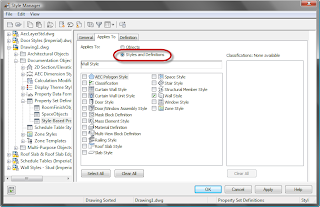
Then pick the object type(s) to whose style(s)/definition(s) the Property Set Defintion is to apply. Go to the Definition tab and add the properties you want in the set, if you have not already done so.
Now that you have a style-based Property Set Definition, you need to attach it to one or more styles/definitions (of the type you chose on the Applies To tab). In the Style Manager, create/edit such a style or definition. On the General Tab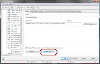 click on the Property Sets... button. This will open the Edit Property Set Data dialog. If your style or definition does not already have a style-based Property Set attached, the dialog will be blank. Click on the Add Property Sets button (right button at the lower left corner). Note that the button will not be active if there are no style-based Property Sets in the current drawing that apply to the object style/definition being edited and that have not already been added. In the Add Property Sets dialog, review the list of eligible Property Sets and make certain that a check mark is in front of all those you wish to add (and not in front of any you do not want to add), and then click OK to add the Property Sets.
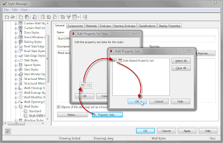 This will return you to the Edit Property Set Data dialog, and you can review the attached properties and, if there are manual properties, you can set the desired values. Also note that now that this style has a Property Set added, the Remove Property Sets button is now active (right button at lower left, next to Add Property Sets button). Click OK to accept the changes you made, and now your style-based Property Set is attached and the Properties therein are available to Schedule Tables and Schedule Tags.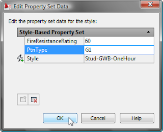
For office-standard style-based Property Sets, you will want to add the set to your style/definition source file, so when users add the style/definition to a drawing, the Property Set is already attached.
Creating a style-based Property Set is quite easy. When creating the Property Set Definition in the Style Manager, indicate that it should apply to Styles and Definitions by using the radio button at the top of the Applies To tab.

Then pick the object type(s) to whose style(s)/definition(s) the Property Set Defintion is to apply. Go to the Definition tab and add the properties you want in the set, if you have not already done so.
Now that you have a style-based Property Set Definition, you need to attach it to one or more styles/definitions (of the type you chose on the Applies To tab). In the Style Manager, create/edit such a style or definition. On the General Tab
 click on the Property Sets... button. This will open the Edit Property Set Data dialog. If your style or definition does not already have a style-based Property Set attached, the dialog will be blank. Click on the Add Property Sets button (right button at the lower left corner). Note that the button will not be active if there are no style-based Property Sets in the current drawing that apply to the object style/definition being edited and that have not already been added. In the Add Property Sets dialog, review the list of eligible Property Sets and make certain that a check mark is in front of all those you wish to add (and not in front of any you do not want to add), and then click OK to add the Property Sets.
 This will return you to the Edit Property Set Data dialog, and you can review the attached properties and, if there are manual properties, you can set the desired values. Also note that now that this style has a Property Set added, the Remove Property Sets button is now active (right button at lower left, next to Add Property Sets button). Click OK to accept the changes you made, and now your style-based Property Set is attached and the Properties therein are available to Schedule Tables and Schedule Tags.
For office-standard style-based Property Sets, you will want to add the set to your style/definition source file, so when users add the style/definition to a drawing, the Property Set is already attached.
June 06, 2011
Revit Tip - Unwanted Linework Revisited
Thanks to a comment posted by Andrew to my Revit Tip - Masking Regions post, I am a step further along on my Revit journey. He correctly pointed out that the Linework tool would be a better choice for getting rid of the unwanted line.
On the Modify ribbon tab, on the View panel, click on the Linework tool, shown below in Revit Architecture 2011.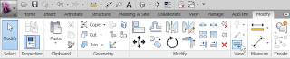 (As always, click on any reduced-size image to see the image full size. Use the Back button on your browser to return here.)
On the Modify|Linework ribbon tab, on the Line Style Panel, set the Line Style to <Invisible lines> in the Line Style drop down list.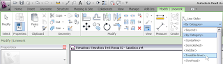 Now you can select the unwanted linework in the View in which you do not want to see it, and make it invisible with a single click. That is far more efficient than using a Masking Region to hide a single line.
If you change your mind later, you can restore the linework you made invisible by using the same Linework tool and setting the Line Style to <By Category> (or any other visible Line Style, if you do not want to use its default appearance).
On the Modify ribbon tab, on the View panel, click on the Linework tool, shown below in Revit Architecture 2011.
 (As always, click on any reduced-size image to see the image full size. Use the Back button on your browser to return here.)
On the Modify|Linework ribbon tab, on the Line Style Panel, set the Line Style to <Invisible lines> in the Line Style drop down list.
 Now you can select the unwanted linework in the View in which you do not want to see it, and make it invisible with a single click. That is far more efficient than using a Masking Region to hide a single line.
If you change your mind later, you can restore the linework you made invisible by using the same Linework tool and setting the Line Style to <By Category> (or any other visible Line Style, if you do not want to use its default appearance).
June 01, 2011
Update 2 for ACA 2011 Now Available
You can download Update 2 for AutoCAD® Architecture 2011 here.
According to the Readme, this Update is NOT cumulative; you will need to install Update 1 first, if you have not already done so. Be certain to read through the entire Readme before installing the update. According to the Readme, the following ACA items have been addressed in Update 2:
Annotation Scaling
Detail Components
Doors/Windows
Drawing Management
General UI
Multi-View Blocks
OpenLight
Structural Members
Walls
See my previous article, for the Updates addressed by Update 1.
According to the Readme, this Update is NOT cumulative; you will need to install Update 1 first, if you have not already done so. Be certain to read through the entire Readme before installing the update. According to the Readme, the following ACA items have been addressed in Update 2:
Annotation Scaling
- If two drawing units are different, the annotative blocks of the previous drawing version might be inserted with incorrect scale.
Detail Components
- Some detail components might not be added in the UK profile after installing Update 1.
Doors/Windows
- When you insert doors or windows evenly between the grid line or between walls, the elevation of the inserted doors or windows may result to a zero value.
Drawing Management
- Clearing the XML file in the current project may cause AutoCAD Architecture to crash.
- Renaming or renumbering the sheet in the Project Navigator may cause AutoCAD Architecture to crash.
General UI
- Accessing some tools from the Tool palettes may cause AutoCAD Architecture to crash.
Multi-View Blocks
- Exporting Multi-View Blocks to AutoCAD may result in incorrect sizes.
- In 3D shaded visual styles, a Multi-View Block created from circle with specified thickness might be drawn double.
OpenLight
- When the OpenLight plug-in is installed, the changes in the display configurations may not be maintained.
Structural Members
- When the start offset of a structural member is larger than its logical length, may cause AutoCAD Architecture to crash.
Walls
- Changing the view cube from parallel to perspective from the shortcut menu after selecting a wall may cause AutoCAD Architecture to crash.
- Clicking the Add Vertex button for some walls while editing in-place may cause AutoCAD Architecture to crash.
- Converting a 3D solid object created by extruding profile along a certain path to wall may cause irregular geometry.
- If the walls are with separate wall components which have bottom elevation offset, these walls may not display correctly in plan view.
See my previous article, for the Updates addressed by Update 1.
May 06, 2011
Revit Tip - Masking Regions
This may be old news to more experienced Revit users, but this was not covered in the "basics" training and was not discovered by anyone on my project team during the design and documentation phases. When generating elevations and sections from the Revit model, there will often be "artifacts" in the view that you would not want to see in the final elevation or section. Or there will be items that do not appear as you would like, but the effort to edit the model to get them to show properly in elevation or section is simply not worth it or the overhead of modeling the necessary detail slows the model excessively.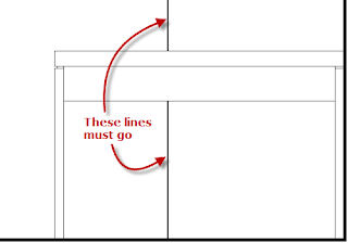
Masking Regions to the rescue! The problem we had with the Masking Regions was that the items to be masked almost always intersected or abutted linework that we wanted to keep. The boundary lines for Masking Regions default to invisible lines, which makes sense, but, unfortunately, if you place the boundary at the linework you want to keep, the mask extends to the midpoint of that linework. This is particularly noticeable on linework with a heavy lineweight, but is true for all linework.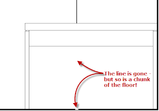
The initial solution was to grip edit the Masking Region and pull it back slightly, to avoid losing desired graphics. This was tedious, and, when done poorly, either left a (smaller) divot in the linework to remain, or left a small part of the line to be masked protruding. While my efforts during construction documents were mostly focused in other areas, I have had to make revisions during construction, and found this process to be very unsatisfactory, until I realized that the boundary lines do not have to be invisible, nor do they all have to be the same.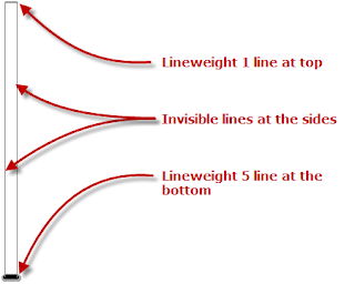 By matching the Line Style of the boundary lines to that of the linework for segments that align with linework to remain, the Masking Region fully hides the unwanted linework without removing a piece of the linework that is to remain.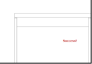

Masking Regions to the rescue! The problem we had with the Masking Regions was that the items to be masked almost always intersected or abutted linework that we wanted to keep. The boundary lines for Masking Regions default to invisible lines, which makes sense, but, unfortunately, if you place the boundary at the linework you want to keep, the mask extends to the midpoint of that linework. This is particularly noticeable on linework with a heavy lineweight, but is true for all linework.

The initial solution was to grip edit the Masking Region and pull it back slightly, to avoid losing desired graphics. This was tedious, and, when done poorly, either left a (smaller) divot in the linework to remain, or left a small part of the line to be masked protruding. While my efforts during construction documents were mostly focused in other areas, I have had to make revisions during construction, and found this process to be very unsatisfactory, until I realized that the boundary lines do not have to be invisible, nor do they all have to be the same.
 By matching the Line Style of the boundary lines to that of the linework for segments that align with linework to remain, the Masking Region fully hides the unwanted linework without removing a piece of the linework that is to remain.
April 28, 2011
Revit - Rectangle Tool in Families
Here is a tip that I picked up watching one of The Revit Kid's videos a while back, and it has proved to be sufficiently useful that I thought I would make note of it here. When drawing linework that you intend to constrain to Reference Planes in a Revit Family, if you are drawing a rectangle, use the Rectangle tool.
Not only does it allow you to draw four lines with two clicks, but it also allows you to draw those lines in place and then activate the constraints. No need to use the Align tool after drawing the linework. (As always, you can click on a reduced-to-fit image to see it full size. Use the Back button in your browser to return to the blog article.)

Not only does it allow you to draw four lines with two clicks, but it also allows you to draw those lines in place and then activate the constraints. No need to use the Align tool after drawing the linework.
 (As always, you can click on a reduced-to-fit image to see it full size. Use the Back button in your browser to return to the blog article.)
April 25, 2011
Controlling Did You Know Balloon Notifications
If you never made much use of the Communication Center, you may not miss its absense on the InfoCenter toolbar in the upper right corner. (I am assuming that the shipping version and the release candidate beta have the same interface elements and that this was not added back in at the last minute.)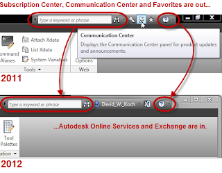
Once you have to manually close a Did You Know message more than one time, you may recall that you were able to have the Did You Know messages close after a period of time that you specified, using the InfoCenter Settings dialog that you accessed from the Communication Center.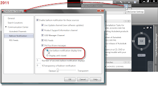 Now how are you going to make those settings?
Fortunately, you still can do so, but you need to know how to access the InfoCenter Settings dialog. Open the Options dialog (one way - from the Application Menu - the big red "A" in the upper left corner - choose the Options button at the lower right corner) and on the System tab, in the InfoCenter area in the lower right corner, click the Balloon Notifications button. This will open the InfoCenter Settings dialog and let you change Did You Know messages from Display until closed to Use balloon notification display time. You can set the number of seconds that balloon notifications display and also choose how transparent the balloons are.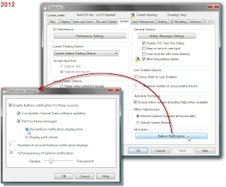 If you do not want to see the Did You Know messages at all, you can also just clear the checkmark in the toggle in front of Did You Know messages (or all balloon notifications).

Once you have to manually close a Did You Know message more than one time, you may recall that you were able to have the Did You Know messages close after a period of time that you specified, using the InfoCenter Settings dialog that you accessed from the Communication Center.
 Now how are you going to make those settings?
Fortunately, you still can do so, but you need to know how to access the InfoCenter Settings dialog. Open the Options dialog (one way - from the Application Menu - the big red "A" in the upper left corner - choose the Options button at the lower right corner) and on the System tab, in the InfoCenter area in the lower right corner, click the Balloon Notifications button. This will open the InfoCenter Settings dialog and let you change Did You Know messages from Display until closed to Use balloon notification display time. You can set the number of seconds that balloon notifications display and also choose how transparent the balloons are.
 If you do not want to see the Did You Know messages at all, you can also just clear the checkmark in the toggle in front of Did You Know messages (or all balloon notifications).
April 22, 2011
Autodesk Discussion Groups and IE9
If you have "upgraded" Internet Explorer to Version 9 and have suddenly found that your posts in the Autodesk Discussion Groups are showing up with a blank message body, try turning on Compatibility View.
Supposedly, there is a button for this at the end of the Address Bar, but I did not have one.
I had to turn on the Menu Bar (which I would have done, anyway) and then chose Tools > Compatibility View while the Discussion Group site was up on the active tab, and then I was able to post a reply and have the text show up.
Supposedly, there is a button for this at the end of the Address Bar, but I did not have one.

I had to turn on the Menu Bar (which I would have done, anyway) and then chose Tools > Compatibility View while the Discussion Group site was up on the active tab, and then I was able to post a reply and have the text show up.

April 09, 2011
Location Property Misread
If you are experiencing Location properties not reading the correct property when working through external references, you may want to see if the problem is similar to one I recently experienced.
A project in my office was being done in ACA 2010, and was not using the Drawing Management (Project Browser/Project Navigator) feature. Space objects were placed in the main "model" file, and had the company standard Property Set attached which includes two Text-type Manual properties for the room name (for two separate lines, set up before attributes in the view block of a Multi-View Block tag could wrap text), a formula property to concatenate those two Manual properties, for use in Schedule Tables and a Manual room number property. The Property Set was an older version, which also has three "residual" properties from the out-of-the-box property set, a Project property for Level, an Integer-type Manual property for the room number "Increment" and a formula property to concatenate the Level and Increment properties. A separate Property Set was also attached to the Spaces to hold a project-specific Text-type Manual property to hold the "room code".
In order to allow additional staff to work simultaneously, the equipment for the project was placed in several different "equipment" files, which were then externally referenced into the main model file. The main model file was also externally referenced into the equipment files, so that the equipment could be located. The equipment had a Property Set that included three Location properties: one for the concatenated formula property for the room name, one for the room number and one for the room code.
There were a number of issues with the state of the files at the time I was consulted. Once I got the needed Property Sets attached, I found that the room code Location property read the information correctly, but the room name and room number properties were displaying *No Project* for a value. I double checked to make certain that the correct properties were being referenced, and that these did not make use of the Project property. All appeared to be set up correctly.
I finally discovered what the problem was (even if I do not understand why it was a problem) - the equipment drawings had our current version of the Property Set for room names and numbers, which no longer have the "residual" Project-based properties. For some reason, the fact that this was different from the version of the Property Set in the main model file caused ACA to become "confused" (no, that is not a technical term) and resulted in ACA grabbing the wrong property values from the main model. I discovered this when I added two more Location properties, referencing the two Manual properties that make up the room name. The Location property referencing the first line property also displayed *No Project*, but the Location property referencing the second line property was displaying the value of the first line property! At that point, I discovered that the Property Set in the equipment drawings was different from the one in the main model file. I did not want to take a chance on losing all of the values for the room names and numbers in the main model file, so I copied the version in that file to the equipment file, and, just like that, the Location properties started referencing the right properties.
So, if you are seeing a Location property in one file referencing the wrong property from a Space in an externally referenced file, one thing to check is whether the Property Set that has the Space property being referenced is identical in both files.
As part of my diagnostics, I opened the ACA 2010 files in both ACA 2011 and Release Candidate Beta 2012, and the problem occurred in those versions, also.
A project in my office was being done in ACA 2010, and was not using the Drawing Management (Project Browser/Project Navigator) feature. Space objects were placed in the main "model" file, and had the company standard Property Set attached which includes two Text-type Manual properties for the room name (for two separate lines, set up before attributes in the view block of a Multi-View Block tag could wrap text), a formula property to concatenate those two Manual properties, for use in Schedule Tables and a Manual room number property. The Property Set was an older version, which also has three "residual" properties from the out-of-the-box property set, a Project property for Level, an Integer-type Manual property for the room number "Increment" and a formula property to concatenate the Level and Increment properties. A separate Property Set was also attached to the Spaces to hold a project-specific Text-type Manual property to hold the "room code".
In order to allow additional staff to work simultaneously, the equipment for the project was placed in several different "equipment" files, which were then externally referenced into the main model file. The main model file was also externally referenced into the equipment files, so that the equipment could be located. The equipment had a Property Set that included three Location properties: one for the concatenated formula property for the room name, one for the room number and one for the room code.
There were a number of issues with the state of the files at the time I was consulted. Once I got the needed Property Sets attached, I found that the room code Location property read the information correctly, but the room name and room number properties were displaying *No Project* for a value. I double checked to make certain that the correct properties were being referenced, and that these did not make use of the Project property. All appeared to be set up correctly.
I finally discovered what the problem was (even if I do not understand why it was a problem) - the equipment drawings had our current version of the Property Set for room names and numbers, which no longer have the "residual" Project-based properties. For some reason, the fact that this was different from the version of the Property Set in the main model file caused ACA to become "confused" (no, that is not a technical term) and resulted in ACA grabbing the wrong property values from the main model. I discovered this when I added two more Location properties, referencing the two Manual properties that make up the room name. The Location property referencing the first line property also displayed *No Project*, but the Location property referencing the second line property was displaying the value of the first line property! At that point, I discovered that the Property Set in the equipment drawings was different from the one in the main model file. I did not want to take a chance on losing all of the values for the room names and numbers in the main model file, so I copied the version in that file to the equipment file, and, just like that, the Location properties started referencing the right properties.
So, if you are seeing a Location property in one file referencing the wrong property from a Space in an externally referenced file, one thing to check is whether the Property Set that has the Space property being referenced is identical in both files.
As part of my diagnostics, I opened the ACA 2010 files in both ACA 2011 and Release Candidate Beta 2012, and the problem occurred in those versions, also.
April 03, 2011
AutoCAD 2012 New Feature - AutoComplete
Another new AutoCAD® 2012 feature that I found useful is AutoComplete, which assists you when typing a command or system variable at the Command: prompt. This will be especially useful to ACA users, who, if you are like me, find typing some of the rather long ACA command names tedious at best and difficult to remember at worst. I know many have set up command aliases for many commonly used command in their ACAD.pgp file, but I find myself typing in most ACA commands sufficiently infrequently that it never seemed worth taking the bother to set up and remember command aliases but often enough to now find AutoComplete useful.
AutoComplete offers several options, which can be configured to your liking by either typing AUTOCOMPLETE at the Command: prompt or by right-clicking in the Command: line window and choosing the AutoComplete flyout on the context menu.
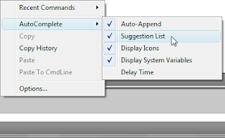 In the headers below, the command line option is given first, followed by the context menu flyout menu choice.
Append/Auto-Append
With the Append option enabled, command and system variable names will be automatically completed, right on the Command: line, as you type. If there are multiple commands that fit what you have typed so far, the first one alphabetically will be completed. The command line option is a Yes/No question; choosing the item on the context menu will toggle the check mark on (= "Yes") or off (= "No").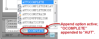
List/Suggestion List
This option determines whether a popup list of commands that start with the characters typed so far will appear. You can then choose the command you want from the list, or continue to type additional characters to reduce the number of commands on the list (or until the command you want is appended, if you have that option turned on). The command line option is a Yes/No question; choosing the item on the context menu will toggle the check mark on (= "Yes") or off (= "No").
Icon/Display Icons
Use this option to determine whether the icon associated with a command is displayed in front of it on the popup list. The command line option is a Yes/No question; choosing the item on the context menu will toggle the check mark on (= "Yes") or off (= "No").
System variables/Display System Variables
Enable this option to include System Variables in the Append and List options; disable it to exclude them. The command line option is a Yes/No question; choosing the item on the context menu will toggle the check mark on (= "Yes") or off (= "No").
Delay/Delay Time
The delay time, entered in seconds, determines how long AutoCAD waits before allowing the Append and List features to be applied, when enabled.
ON
Choosing the ON option will allow the AutoComplete features that have been enabled to be active. Note that if both Append and List are set to "No" (unchecked in the context menu), then using the ON option has no actual effect. But if you previously used the OFF option (see below) to disable the AutoComplete feature when the Append, List or both were set to "Yes", then the "ON" command option will enable AutoComplete with the features that were previously set to "Yes".
OFF
The OFF option disables the AutoComplete function without changing the status of any of the command options. You can later use the ON option to enable the AutoComplete function with the same settings you had prior to using the OFF option.
The ON and OFF options are not available in the right-click context menu. You can turn both the Append and List options off in the context menu to effectively disable the AutoComplete feature, but if you later want both options on, you would have to turn both back on individually.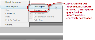 To disable the feature while preserving your settings, use the OFF option of the AutoComplete command at the Command: line.
If you hover over one of the commands in the popup list and ToolTips are enabled and the command has a ToolTip, the ToolTip will display.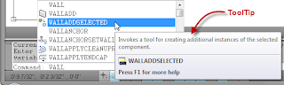
If you load custom LISP routines that define commands, these will also be available in the AutoComplete feature. In the image below, the SELALL command is a custom command I have defined, and after typing "SEL" at the Command: line, the popup list shows the SELALL command and the balance of the SELALL command has been appended, since it is first alphabetically on the list. The SELBLK command is also a LISP-defined custom command.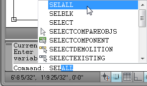
AutoComplete offers several options, which can be configured to your liking by either typing AUTOCOMPLETE at the Command: prompt
 or by right-clicking in the Command: line window and choosing the AutoComplete flyout on the context menu.
 In the headers below, the command line option is given first, followed by the context menu flyout menu choice.
Append/Auto-Append
With the Append option enabled, command and system variable names will be automatically completed, right on the Command: line, as you type. If there are multiple commands that fit what you have typed so far, the first one alphabetically will be completed. The command line option is a Yes/No question; choosing the item on the context menu will toggle the check mark on (= "Yes") or off (= "No").

List/Suggestion List
This option determines whether a popup list of commands that start with the characters typed so far will appear. You can then choose the command you want from the list, or continue to type additional characters to reduce the number of commands on the list (or until the command you want is appended, if you have that option turned on). The command line option is a Yes/No question; choosing the item on the context menu will toggle the check mark on (= "Yes") or off (= "No").

Icon/Display Icons
Use this option to determine whether the icon associated with a command is displayed in front of it on the popup list. The command line option is a Yes/No question; choosing the item on the context menu will toggle the check mark on (= "Yes") or off (= "No").
System variables/Display System Variables
Enable this option to include System Variables in the Append and List options; disable it to exclude them. The command line option is a Yes/No question; choosing the item on the context menu will toggle the check mark on (= "Yes") or off (= "No").
Delay/Delay Time
The delay time, entered in seconds, determines how long AutoCAD waits before allowing the Append and List features to be applied, when enabled.
ON
Choosing the ON option will allow the AutoComplete features that have been enabled to be active. Note that if both Append and List are set to "No" (unchecked in the context menu), then using the ON option has no actual effect. But if you previously used the OFF option (see below) to disable the AutoComplete feature when the Append, List or both were set to "Yes", then the "ON" command option will enable AutoComplete with the features that were previously set to "Yes".
OFF
The OFF option disables the AutoComplete function without changing the status of any of the command options. You can later use the ON option to enable the AutoComplete function with the same settings you had prior to using the OFF option.
The ON and OFF options are not available in the right-click context menu. You can turn both the Append and List options off in the context menu to effectively disable the AutoComplete feature, but if you later want both options on, you would have to turn both back on individually.
 To disable the feature while preserving your settings, use the OFF option of the AutoComplete command at the Command: line.
If you hover over one of the commands in the popup list and ToolTips are enabled and the command has a ToolTip, the ToolTip will display.

If you load custom LISP routines that define commands, these will also be available in the AutoComplete feature. In the image below, the SELALL command is a custom command I have defined, and after typing "SEL" at the Command: line, the popup list shows the SELALL command and the balance of the SELALL command has been appended, since it is first alphabetically on the list. The SELBLK command is also a LISP-defined custom command.

Subscribe to:
Posts (Atom)