My firm is currently using ACA 2010 for most of our production work that is not being done in Revit. Our template file has the IMAGEFRAME variable set to 2, so that the frames are visible but they do not print. (We have all of the "frame" variables set to 2, which can be done all at once by using the FRAME command.)
I have found, however, after starting a new drawing, that the frames around images will plot, particularly those nested within an externally referenced file. I double check the file, and IMAGEFRAME is set to 2, yet the border shows on my plot. I have no explanation for this, but I do have a workaround - if I set the value to 0 (do not show or plot the borders) and then back to 2, the setting "takes" and the borders remain visible but do not plot.
Showing posts with label 2010. Show all posts
Showing posts with label 2010. Show all posts
August 09, 2012


April 09, 2011
Location Property Misread
If you are experiencing Location properties not reading the correct property when working through external references, you may want to see if the problem is similar to one I recently experienced.
A project in my office was being done in ACA 2010, and was not using the Drawing Management (Project Browser/Project Navigator) feature. Space objects were placed in the main "model" file, and had the company standard Property Set attached which includes two Text-type Manual properties for the room name (for two separate lines, set up before attributes in the view block of a Multi-View Block tag could wrap text), a formula property to concatenate those two Manual properties, for use in Schedule Tables and a Manual room number property. The Property Set was an older version, which also has three "residual" properties from the out-of-the-box property set, a Project property for Level, an Integer-type Manual property for the room number "Increment" and a formula property to concatenate the Level and Increment properties. A separate Property Set was also attached to the Spaces to hold a project-specific Text-type Manual property to hold the "room code".
In order to allow additional staff to work simultaneously, the equipment for the project was placed in several different "equipment" files, which were then externally referenced into the main model file. The main model file was also externally referenced into the equipment files, so that the equipment could be located. The equipment had a Property Set that included three Location properties: one for the concatenated formula property for the room name, one for the room number and one for the room code.
There were a number of issues with the state of the files at the time I was consulted. Once I got the needed Property Sets attached, I found that the room code Location property read the information correctly, but the room name and room number properties were displaying *No Project* for a value. I double checked to make certain that the correct properties were being referenced, and that these did not make use of the Project property. All appeared to be set up correctly.
I finally discovered what the problem was (even if I do not understand why it was a problem) - the equipment drawings had our current version of the Property Set for room names and numbers, which no longer have the "residual" Project-based properties. For some reason, the fact that this was different from the version of the Property Set in the main model file caused ACA to become "confused" (no, that is not a technical term) and resulted in ACA grabbing the wrong property values from the main model. I discovered this when I added two more Location properties, referencing the two Manual properties that make up the room name. The Location property referencing the first line property also displayed *No Project*, but the Location property referencing the second line property was displaying the value of the first line property! At that point, I discovered that the Property Set in the equipment drawings was different from the one in the main model file. I did not want to take a chance on losing all of the values for the room names and numbers in the main model file, so I copied the version in that file to the equipment file, and, just like that, the Location properties started referencing the right properties.
So, if you are seeing a Location property in one file referencing the wrong property from a Space in an externally referenced file, one thing to check is whether the Property Set that has the Space property being referenced is identical in both files.
As part of my diagnostics, I opened the ACA 2010 files in both ACA 2011 and Release Candidate Beta 2012, and the problem occurred in those versions, also.
A project in my office was being done in ACA 2010, and was not using the Drawing Management (Project Browser/Project Navigator) feature. Space objects were placed in the main "model" file, and had the company standard Property Set attached which includes two Text-type Manual properties for the room name (for two separate lines, set up before attributes in the view block of a Multi-View Block tag could wrap text), a formula property to concatenate those two Manual properties, for use in Schedule Tables and a Manual room number property. The Property Set was an older version, which also has three "residual" properties from the out-of-the-box property set, a Project property for Level, an Integer-type Manual property for the room number "Increment" and a formula property to concatenate the Level and Increment properties. A separate Property Set was also attached to the Spaces to hold a project-specific Text-type Manual property to hold the "room code".
In order to allow additional staff to work simultaneously, the equipment for the project was placed in several different "equipment" files, which were then externally referenced into the main model file. The main model file was also externally referenced into the equipment files, so that the equipment could be located. The equipment had a Property Set that included three Location properties: one for the concatenated formula property for the room name, one for the room number and one for the room code.
There were a number of issues with the state of the files at the time I was consulted. Once I got the needed Property Sets attached, I found that the room code Location property read the information correctly, but the room name and room number properties were displaying *No Project* for a value. I double checked to make certain that the correct properties were being referenced, and that these did not make use of the Project property. All appeared to be set up correctly.
I finally discovered what the problem was (even if I do not understand why it was a problem) - the equipment drawings had our current version of the Property Set for room names and numbers, which no longer have the "residual" Project-based properties. For some reason, the fact that this was different from the version of the Property Set in the main model file caused ACA to become "confused" (no, that is not a technical term) and resulted in ACA grabbing the wrong property values from the main model. I discovered this when I added two more Location properties, referencing the two Manual properties that make up the room name. The Location property referencing the first line property also displayed *No Project*, but the Location property referencing the second line property was displaying the value of the first line property! At that point, I discovered that the Property Set in the equipment drawings was different from the one in the main model file. I did not want to take a chance on losing all of the values for the room names and numbers in the main model file, so I copied the version in that file to the equipment file, and, just like that, the Location properties started referencing the right properties.
So, if you are seeing a Location property in one file referencing the wrong property from a Space in an externally referenced file, one thing to check is whether the Property Set that has the Space property being referenced is identical in both files.
As part of my diagnostics, I opened the ACA 2010 files in both ACA 2011 and Release Candidate Beta 2012, and the problem occurred in those versions, also.
January 19, 2011
ACA Section Tail Scaling
Here is a heads up to anyone who may be placing Section Marks with "tails" in Model Space from a Layout through a Viewport. The AecCallout command has an apparent defect in the way it creates the anonymous block for the tail. It works fine when placing the Section Mark from the "Model tab" (when "Model" or TILEMODE 1, rather than a "Layout" or TILEMODE 0 is current). It also works correctly when in a Layout and working through a Viewport when the scale of the Viewport is the same as the scale set for "Model".
But if the Viewport's scale is not the same as the "Model" scale, then the anonymous block that gets created is improperly sized. The correct annotation scale (matching that of the Viewport) is applied to the tail block, but the improper size of the block definition results in the final block displaying the same size as one placed through a Viewport that has the same scale as "Model".
To avoid this problem, you can do one of the following:
The block at the other end of the Section Mark, displaying the Section Number and, possibly, the Sheet Number, does not suffer from this defect.
But if the Viewport's scale is not the same as the "Model" scale, then the anonymous block that gets created is improperly sized. The correct annotation scale (matching that of the Viewport) is applied to the tail block, but the improper size of the block definition results in the final block displaying the same size as one placed through a Viewport that has the same scale as "Model".
To avoid this problem, you can do one of the following:
- Place all callouts from the "Model tab" (TILEMODE 1), setting the desired drawing scale prior to placement.
- Remember to switch to "Model"/TILEMODE 1 and set the drawing scale to match that of the Viewport and then switch back to the Layout.
- Place the callout in the Viewport and then, after placement, change X-scale factor of the block to get it to be the right size [Viewport scale factor/Model scale factor]. The anonymous block created has uniform scaling, so the change to the X-scale factor will be applied to the Y- and Z-scale factors as well.
The block at the other end of the Section Mark, displaying the Section Number and, possibly, the Sheet Number, does not suffer from this defect.
September 04, 2010
Hatch Editing With Grips - 2010 & Later
Here is an AutoCAD® feature that has been around since the 2010 release, and now that I am using that in the office, I thought it worth a mention, given how easy it makes updating non-associative hatches - even those created in previous releases. Given the problems associative hatches can have when an external reference or an AEC object is part of the boundary (when opening the file, the hatch often tries to resolve itself before all of the bounding objects have been loaded and resolved), I had taken to drawing polyline boundaries on a non-plotting layer and making hatches associative to that, so that I could edit the boundary easily should the area of hatch need to be changed in the future. Having been on the 2004 release for quite some time for production work, I was not able to take advantage of the ability to generate a boundary of an existing, non-associative hatch and make the hatch associative to it. The new grip editing feature makes this additional step unecessary.
To demonstrate the grip editing feature, I have created a square, non-associative hatch (and deleted the original bounding polyline), and drawn another polyline, to which I will extend the hatch, using grip edits.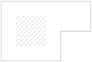
Selecting the hatch reveals a number of grips. The center grip allows you to move the entire hatch, and was present in releases previous to 2010. The Vertex and Edge grips are new in 2010 (and are also present in 2011). ACA users should be familiar with hovering the cursor over a grip to get a tooltip, possibly listing options, and that technique works here as well.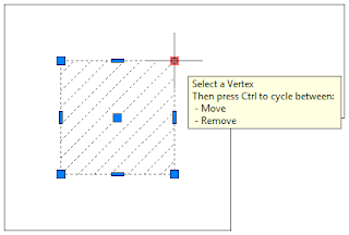 Hovering over a square grip at the perimeter of the hatch (Vertex) reveals that selecting that grip will allow you to initially move the Vertex to a new location, and pressing the CTRL key will cycle to the Remove option, allowing you to delete the Vertex.
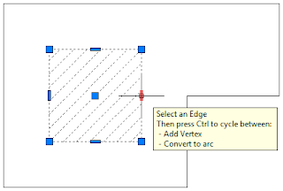 Hovering over a rectangular Edge grip on a straight segment at the hatch perimeter shows that the intial action on selecting the grip will be to add a new Vertex, and that pressing the CTRL key will cycle to converting that Edge to an arc.
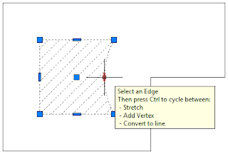 Hovering over the rectangular grip of an arc Edge of a hatch indicates that the initial action is to stretch the arc and that you can use the CTRL key to cycle to add a new Vertex and then to convert the arc to a line.
ACA users that have used grip edits on AEC objects will have to remind themselves that the Edge grips can NOT be used to stretch a straight segement, as they can for AEC Polygons.
To make the square hatch fill the drawn polyline with grip editing, use the Move option to relocate the four existing Vertices to Vertices on the polyline.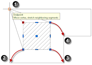 To fill in the remainder, select the Edge grip that is not on a segment of the polyline and use the Add Vertex mode to add a fifth...
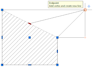 ...and sixth Vertex...
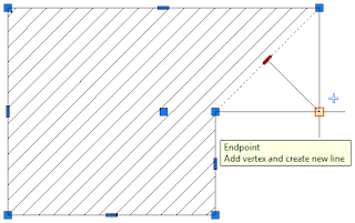 ...filling the polyline.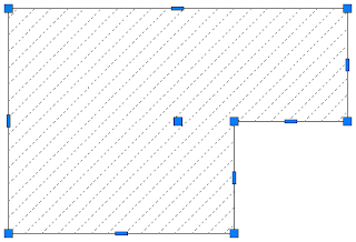
You can, of course, accomplish this simple edit in one step, by selecting the original square hatch, right clicking, choosing Set Boundary from the context menu and then picking the polyline.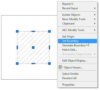 But in a typical drawing, where you have a lot more linework and, perhaps, several adjoining hatches, and where the linework defining the hatch edges is not a single polyline, I have found grip editing of hatches to be a very useful feature, and one that has virtually eliminated the need to delete an existing hatch and then rehatch the area.
To demonstrate the grip editing feature, I have created a square, non-associative hatch (and deleted the original bounding polyline), and drawn another polyline, to which I will extend the hatch, using grip edits.

Selecting the hatch reveals a number of grips. The center grip allows you to move the entire hatch, and was present in releases previous to 2010. The Vertex and Edge grips are new in 2010 (and are also present in 2011). ACA users should be familiar with hovering the cursor over a grip to get a tooltip, possibly listing options, and that technique works here as well.
 Hovering over a square grip at the perimeter of the hatch (Vertex) reveals that selecting that grip will allow you to initially move the Vertex to a new location, and pressing the CTRL key will cycle to the Remove option, allowing you to delete the Vertex.
 Hovering over a rectangular Edge grip on a straight segment at the hatch perimeter shows that the intial action on selecting the grip will be to add a new Vertex, and that pressing the CTRL key will cycle to converting that Edge to an arc.
 Hovering over the rectangular grip of an arc Edge of a hatch indicates that the initial action is to stretch the arc and that you can use the CTRL key to cycle to add a new Vertex and then to convert the arc to a line.
ACA users that have used grip edits on AEC objects will have to remind themselves that the Edge grips can NOT be used to stretch a straight segement, as they can for AEC Polygons.
To make the square hatch fill the drawn polyline with grip editing, use the Move option to relocate the four existing Vertices to Vertices on the polyline.
 To fill in the remainder, select the Edge grip that is not on a segment of the polyline and use the Add Vertex mode to add a fifth...
 ...and sixth Vertex...
 ...filling the polyline.
You can, of course, accomplish this simple edit in one step, by selecting the original square hatch, right clicking, choosing Set Boundary from the context menu and then picking the polyline.
 But in a typical drawing, where you have a lot more linework and, perhaps, several adjoining hatches, and where the linework defining the hatch edges is not a single polyline, I have found grip editing of hatches to be a very useful feature, and one that has virtually eliminated the need to delete an existing hatch and then rehatch the area.
August 18, 2010
Revit - Wall Openings and Room Separation Lines
Interesting Observations to Keep in Mind in the Future [based on the Wall having a Base Offset of 0 (zero)]:
So, in order to edit the width of a Wall Opening that has a Room Separation Line with an endpoint on the Wall Opening edge you wish to move, you either need to stretch the Room Separation Line to get the endpoint off of the Wall Opening Edge -OR- you need to select the Wall, "disallow join" at that edge using the "Disallow Join" grip. If you can easily stretch the Wall Separation Line to get its endpoint at the desired new location of the Wall Opening edge, then doing that and then editing the Wall Opening would be the least tedious way to proceed. If not, either method should work; use the one you prefer.
- A Wall Opening with a Base Offset of 0 or less (extends to the Wall's bottom or below) renders that Wall incapable of acting as a Room separator. In other words, the Room will extend through the Opening in search of bounding elements beyond (left opening in the images below).
- A Wall Opening with a non-zero, positive Base Offset will act a Room separator, even if the top of the Wall Opening is at or above the top of the Wall or if the Room's Base Offset puts the bottom of the Room above the bottom of the Wall Opening (right opening in the images below).
So, it would appear that the condition at the associated Level is what determines whether or not a Wall Opening will allow a Room to pass through or not. - Adding a Room Separation Line to close the breach and having the endpoints of the Room Separation line at an edge of the Wall Opening disables the stretch grip at that edge and also prevents that edge from working with the Align tool. (If both ends of the Room Separation Line are at the edge of the Wall Opening, then neither stretch grip is available and neither edge can be Aligned.
- Stretching the Room Separation Line beyond the extents of the Wall Opening allows the Wall Opening end to be grip edited or Aligned, but will result in warnings about the overlapping Wall and Room Separation Line. If those warnings do not bother you, you can leave the Wall Separation Line beyond the Wall Opening until you are satisfied with the location of the Wall Opening.
- Selecting the Wall will display a "Disallow Join" grip at each edge of the Wall Opening. Clicking on one of those grips will reactivate the stretch grip and the ability to Align that edge. Doing so, and enlarging the Wall Opening will allow Rooms to flow through, so you will also need to extend the Room Separation Line if you want to prevent the Room(s) from passing through.


So, in order to edit the width of a Wall Opening that has a Room Separation Line with an endpoint on the Wall Opening edge you wish to move, you either need to stretch the Room Separation Line to get the endpoint off of the Wall Opening Edge -OR- you need to select the Wall, "disallow join" at that edge using the "Disallow Join" grip. If you can easily stretch the Wall Separation Line to get its endpoint at the desired new location of the Wall Opening edge, then doing that and then editing the Wall Opening would be the least tedious way to proceed. If not, either method should work; use the one you prefer.
July 26, 2010
Frozen Ribbon
No, it is not a new way to beat the summer heat (my apologies to readers in the southern hemisphere, who may be more interested in a way to stay warm, but this has been a particularly brutal summer here in Philadelphia); it is a frequently reported occurrence in AutoCAD® Architecture 2010 and 2011. Often triggered by the use of the MTEXT command, the freeze occurs if you have more than one CUIX file loaded and two or more each have a contextual ribbon tab (such as the Text Editor tab triggered by the MTEXT or MTEDIT commands) that is triggered by the same command or object selection.
This most frequently happens when both the ACA.cuix and ACAD.cuix files are loaded simultaneously, often so that an ACA user can have access to elements in the ACAD.cuix file that are not part of the ACA.cuix file. Unfortunately, loading both as they are, out-of-the-box, will result in having multiple contextual ribbon tabs for the same triggering action.
The solution is to either not load both at the same time, or, if you must have access to items in both, to create a custom CUIX file that has the items you want from the ACAD.cuix file, but does not have the contextual ribbon tabs (or at least not any that overlap those in the ACA.cuix file). You will need to decide whether it is easier to make a copy of the ACAD.cuix file under another name, and remove the overlapping contextual ribbon tabs -OR- set up a new CUIX file and transfer only the items you want/need from the ACAD.cuix file.
This most frequently happens when both the ACA.cuix and ACAD.cuix files are loaded simultaneously, often so that an ACA user can have access to elements in the ACAD.cuix file that are not part of the ACA.cuix file. Unfortunately, loading both as they are, out-of-the-box, will result in having multiple contextual ribbon tabs for the same triggering action.
The solution is to either not load both at the same time, or, if you must have access to items in both, to create a custom CUIX file that has the items you want from the ACAD.cuix file, but does not have the contextual ribbon tabs (or at least not any that overlap those in the ACA.cuix file). You will need to decide whether it is easier to make a copy of the ACAD.cuix file under another name, and remove the overlapping contextual ribbon tabs -OR- set up a new CUIX file and transfer only the items you want/need from the ACAD.cuix file.
May 17, 2010
ACA 2010 Update 2 Now Available
Update 2 for AutoCAD Architecture 2010 (yes, 2010, not 2011) is now available from the Autodesk website. Update 2 includes Update 1, so if you have not yet installed Update 1 (like me), you can just install Update 2.
According to the AutoCAD Architecture 2010 Update 2 Readme, the following defects have been fixed (list includes both Update 1 and Update 2):
AEC Dimensions
Update 1
API
Update 1
Doors/Windows/Openings
Update 2
Drawing Management
Update 2
Export to AutoCAD
Update 2
External References
Update 1
GBXML
Update 2
General UI
Update 2
IFC
Update 1
Layers
Update 1
Multiview Blocks
Update 2
Performance
Update 1
Property Palette
Update 1
Save
Update 2
Schedules
Update 1
Sections
Update 1
Structural Members
Update 1
Spaces
Update 2
Wall Objects
Update 1
According to the AutoCAD Architecture 2010 Update 2 Readme, the following defects have been fixed (list includes both Update 1 and Update 2):
AEC Dimensions
Update 1
- Multiple overlapping windows may lead to incorrect dimensions.
API
Update 1
- AutoCAD Architecture might crash when trying to define a Display Theme style using .NET API.
Doors/Windows/Openings
Update 2
- When a custom block is applied to a door, window, or door-window assembly, the block will be visible even if it is not within the cut plane range.
- Sometimes, you cannot insert an opening in a wall in a certain cleanup group.
Drawing Management
Update 2
- AutoCAD Architecture may crash when you repath certain projects with no drawings open.
- Renaming items in the Project Navigator, and repathing the project may cause AutoCAD Architecture to crash.
Export to AutoCAD
Update 2
- Export to Autocad sometimes causes AutoCAD Architecture to crash.
External References
Update 1
- Openings in external references with negative Z value are placed at an incorrect position.
- When you execute UNDO command after binding an external reference, AutoCAD Architecture may become unresponsive.
- AutoCAD Architecture may crash if you unload an external reference, attach it again, and then execute an UNDO.
GBXML
Update 2
- Duplicate openings are created in gbXML output when walls are slightly off from being perpendicular to each other.
General UI
Update 2
- Checkboxes are not displayed correctly on the Object Snap tab of the Drafting Settings dialog on Windows 7.
IFC
Update 1
- Slabs may have the wrong elevation when imported from an IFC file due to an incorrect thickness offset.
- Exporting a drawing to IFC may create incorrect IFC GUIDs for AEC objects.
- Importing IFC files that contain certain material settings may crash.
- Space exported to IFC have the IFC type of IFCTYPEOBJECT instead of IFCSPACETYPE.
- When you import an IFC file, containing a space that uses a negative value for extrusion, the extrusion is in the wrong direction.
- Importing an IFC file fails if it contains a 3D vector for True North direction.
Layers
Update 1
- The "New layer from Standard" button doesn't work in localized versions.
- Layer description fields are not automatically populated in all cases.
- When the Layer Properties Manager is open, opening a drawing sometimes causes AutoCAD Architecture to crash.
Multiview Blocks
Update 2
- When AutoCAD Architecture and Civil 3D are installed side by side, AutoCAD Architecture crashes on executing MVBLOCKADD command.
Performance
Update 1
- Response is very slow when using Dynamic UCS and objects are Isolated.
- Sometimes, it takes a long time to complete an UNDO after a COPY.
Property Palette
Update 1
- Changing an entry to one that is the first characters of the previous entry will not work in some fields.
Save
Update 2
- When you save a drawing to a previous version, sometimes, you are not warned about possible data loss.
Schedules
Update 1
- Schedules are not sorted as expected when values are a combination of numeric and alphabetic characters.
- Sometimes, schedule table data is not rounded off as specificed in the property data format.
Sections
Update 1
- Some objects imported from Inventor display as points in 2D Sections.
- When a window or door window assembly is sectioned, some linework may be missing in the section.
Structural Members
Update 1
- Custom block based on 3D Solids using Boolean operations are always placed at the start point.
Spaces
Update 2
- AutoCAD Architecture may crash when a spaced update is triggered for a large number of spaces within an external reference.
Wall Objects
Update 1
- AutoCAD Architecture might hang when opening certain drawings that contain modified Wall Endcaps.
- Window openings may not be created due to Wall Plan Modifiers.
- Using Refedit on a block containing Wall Object may cause a crash.
- When working on a project located on a slow network, the wall and curtain wall tools are slow to respond.
- Some walls in an external reference display solution tips when the units of the host drawing are different from that of the external reference.
- AutoCAD Architecture will crash when you delete a component of a wall which is on a locked layer.
March 10, 2010
AutoCAD® Architecture 2010 - UI Changes, Part 8 - The Ribbon, Manage Tab
Manage Tab
The Manage tab is the sixth static (always available) tab provided in the out-of-the-box ACA CUI. The image below and all screen captures in this article are based on the shipping version.
Navigate Panel
The Action Recorder Panel contains commands related to using the Action Recorder to save, edit and play back command sequences.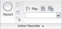 The Record command button starts the Action Recorder (ACTRECORD command). The Insert message command button allows you to insert a message in the Action tree, which will then be displayed during playback (ACTUSERMESSAGE command). The Insert Base Point command button is used to establish a point using absolute coordinates, for use by the prompts that follow in the macro (ACTBASEPOINT command). The Pause for User Input command button allows you to insert a request for user input in the macro (ACTUSERINPUT command). The Play command button plays back the macro selected in the Action Macro drop-down list. The Preference command button allows you to determine the behavior of the Action Recorder panel during recording and playback as well as indicate whether or not you want to be prompted for a macro name when recording is stopped. The Manage Action Macros command button allows you to copy, rename, modify or delete action macro files (ACTMANAGER). The Available Action Macro drop-down list allows you to choose from a list of available macros. The chosen macro is available for playback and is displayed in the Action Tree. The ACTMANAGER command can also be launched from the last item on the list.
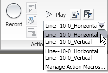 Click on the Action Recorder title bar to expand the panel and reveal the action tree. The contents of the macro chosen on the drop-down list will be displayed in the Action Tree.
CAD Standards Panel
The CAD Standards Panel contains commands related to the AutoCAD® CAD Standards feature.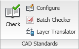 The Check command button runs the CHECKSTANDARDS command to check the current drawing for standards violations. The Configure command button allows you to associate the current drawing with one or more standards files (STANDARDS command). The Batch Checker command button allows you to specify one or more drawings to be checked (BATCHSTANDARDSCHECKER command). The Layer Translator command button runs the LAYTRANS command, allowing you to map the layers in the current drawing to layer names and properties in another drawing file or in a standards file, and then convert the layers in the current drawing based on that mapping.
Project Standards Panel
The Project Standards Panel contains commands related to the AutoCAD Architecture Project Standards feature. You must be working in an AutoCAD Architecture project (using Project Browser and Project Navigator) in order to make use of these tools.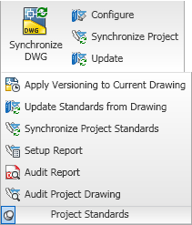 The Synchronize DWG command button will update the current drawing using the styles and settings defined in the project standards drawing(s) for the current project (SYNCHRONIZEPROJECTDRAWING command). The Configure command button allows you to indicate the project standards with which the current drawing will synchronize (PROJECTSTANDARDS command). The Synchronize Project command button runs the SYNCHRONIZEPROJECT command, which will synchronize all of the drawings in a project to the styles and settings in the project standards drawing(s). The Update command button will update the project standards check file (AutoCAD standards) for each file in the project. Select the Project Standards title bar to expand the panel and reveal additional command buttons related to Project Standards: Apply Versioning to Current Drawing (VERSIONMODIFIEDOBJECTS), Update Standards from Drawing (UPDATESTANDARDS), Synchronize Project Standards (SYNCHRONIZESTANDARDS), Setup Report (PROJECTSTANDARDSSETUPREPORT), Audit Report (AUDITPROJECT) and Audit Project Drawing (AUDITPROJECTDRAWING).
Style & Display Panel
The Style & Display Panel offers commands related to AutoCAD Architecture styles and display system.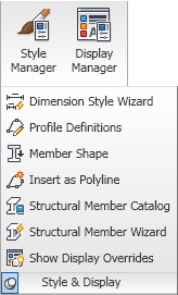 The Style Manager command button opens the Style Manager, allowing you to create, edit and/or delete styles and definitions (STYLEMANAGER). The Display Manager command button opens the Display Manager, so that you can create and/or edit drawing default settings for Display Representations, create and/or edit Display Representation Sets and create and/or edit Display Configurations (DISPLAYMANAGER). Click on the Style & Display title bar to expand the panel and reveal seven additional command buttons. The Dimension Style Wizard command button opens the AEC Dimension Display Wizard, allowing you to change the display properties of AEC Dimension Styles (DIMWIZARD). The Profile Definitions command button opens the Style Manager, filtered for Profile Definitions (PROFILEDEFINE). The Member Shape command button opens the Insert Member Shapes dialog, which allows you to insert one of the structural member shapes defined in the drawing (MEMBERSHAPEINSERT). The Insert as Polyline command button allows you to insert a profile defined in the current drawing as a polyline (PROFILEASPOLYLINE). The Structural Member Catalog command button opens the Structural Member Catalog dialog, which allows you to create Structural Member Styles (and the associated Structural Member Shapes) from a listing of predefined, industry-standard shapes (MEMBERCATALOG). The Structural Member Wizard command button opens the Structural Member Style Wizard dialog, which allows you to create Structural Member Styles based on user-input dimensions for a variety of basic shapes (MEMBERSTYLEWIZARD). The Show Display Overrides command button (SHOWDISPLAYOVERRIDES) allows you to easily identify objects that have an object-level display override by highlighting and/or listing them.
Applications Panel
The Applications Panel has commands related to custom applications that can be run in AutoCAD Architecture, such as AutoLISP or VBA routines.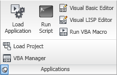 The Load Application command button runs the APPLOAD command, allowing you to load and unload custom applications and to add customizations to the Startup Suite, which will then be loaded each time you start AutoCAD Architecture. The Run Script command button allows you to execute script file (SCRIPT command). The Visual Basic Editor command button displays the Visual Basic Editor, allowing you to edit VBA projects (VBAIDE). The Visual LISP Editor command button runs the VLISP command, calling up the Visual LISP Integrated Development Environment window, where you can create and edit LISP routines. The Run VBA Macro allows you to run, edit or delete a VBA macro (VBARUN). Click on the Applications title bar to expand the panel and reveal two additional command buttons: Load Project, to load a global VBA project into the current work session (VBALOAD) and VBA Manager, to manage your VBA projects in a dialog box (VBAMAN). Note that in the 2010 release, Microsoft® Visual Basic® for Applications software is not installed when AutoCAD Architecture is installed. You can download the files needed to use VBA in AutoCAD at http://www.autodesk.com/vba-download.
Customization Panel
The Customization Panel has commands related to customizing the AutoCAD Architecture user interface.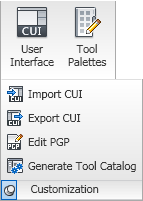 The User Interface command button opens the Customize User Interface dialog, which gives you full access to customizing most aspects of the user interface (CUI command). The Tool Palettes command button opens the Customize dialog, allowing you to customize the organization of tool palettes and tool palette groups, the one part of the interface not covered by the CUI dialog (Customize command). Click on the Customization title bar to expand the panel and reveal four additional command buttons. The Import CUI command button opens the Customize User Interface dialog, with the Transfer tab current, ready to transfer items from an enterprise or partial CUIX file to the main CUIX file (CUIIMPORT command). The Export CUI command button also opens the Customize User Interface dialog to the Transfer tab and allows you to export items from the main customization file to an enterprise or partial CUIX file (CUIEXPORT command). In fact, you can use either of those tools to move files between the main CUIX file and any other CUIX file you choose to open. The only difference is the Import CUI command button puts the main CUIX file on the right side, and the Export CUI command button puts the main CUIX file on the left side. The Edit PGP command button opens the first ACAD.pgp file found in the search path for editing (on my computer, in Notepad). The Generate Tool Catalog command button opens the Populate Tool Catalog from Content Drawings dialog, which allows you to create tools for selected ACA object types from a selected source file and place the tools in a new or existing tool catalog (AECTOOLCATALOGGENERATOR command). The tools can be created in Categories or in Palettes.
The Manage tab is the sixth static (always available) tab provided in the out-of-the-box ACA CUI. The image below and all screen captures in this article are based on the shipping version.

Navigate Panel
The Action Recorder Panel contains commands related to using the Action Recorder to save, edit and play back command sequences.
 The Record command button starts the Action Recorder (ACTRECORD command). The Insert message command button allows you to insert a message in the Action tree, which will then be displayed during playback (ACTUSERMESSAGE command). The Insert Base Point command button is used to establish a point using absolute coordinates, for use by the prompts that follow in the macro (ACTBASEPOINT command). The Pause for User Input command button allows you to insert a request for user input in the macro (ACTUSERINPUT command). The Play command button plays back the macro selected in the Action Macro drop-down list. The Preference command button allows you to determine the behavior of the Action Recorder panel during recording and playback as well as indicate whether or not you want to be prompted for a macro name when recording is stopped. The Manage Action Macros command button allows you to copy, rename, modify or delete action macro files (ACTMANAGER). The Available Action Macro drop-down list allows you to choose from a list of available macros. The chosen macro is available for playback and is displayed in the Action Tree. The ACTMANAGER command can also be launched from the last item on the list.
 Click on the Action Recorder title bar to expand the panel and reveal the action tree. The contents of the macro chosen on the drop-down list will be displayed in the Action Tree.
CAD Standards Panel
The CAD Standards Panel contains commands related to the AutoCAD® CAD Standards feature.
 The Check command button runs the CHECKSTANDARDS command to check the current drawing for standards violations. The Configure command button allows you to associate the current drawing with one or more standards files (STANDARDS command). The Batch Checker command button allows you to specify one or more drawings to be checked (BATCHSTANDARDSCHECKER command). The Layer Translator command button runs the LAYTRANS command, allowing you to map the layers in the current drawing to layer names and properties in another drawing file or in a standards file, and then convert the layers in the current drawing based on that mapping.
Project Standards Panel
The Project Standards Panel contains commands related to the AutoCAD Architecture Project Standards feature. You must be working in an AutoCAD Architecture project (using Project Browser and Project Navigator) in order to make use of these tools.
 The Synchronize DWG command button will update the current drawing using the styles and settings defined in the project standards drawing(s) for the current project (SYNCHRONIZEPROJECTDRAWING command). The Configure command button allows you to indicate the project standards with which the current drawing will synchronize (PROJECTSTANDARDS command). The Synchronize Project command button runs the SYNCHRONIZEPROJECT command, which will synchronize all of the drawings in a project to the styles and settings in the project standards drawing(s). The Update command button will update the project standards check file (AutoCAD standards) for each file in the project. Select the Project Standards title bar to expand the panel and reveal additional command buttons related to Project Standards: Apply Versioning to Current Drawing (VERSIONMODIFIEDOBJECTS), Update Standards from Drawing (UPDATESTANDARDS), Synchronize Project Standards (SYNCHRONIZESTANDARDS), Setup Report (PROJECTSTANDARDSSETUPREPORT), Audit Report (AUDITPROJECT) and Audit Project Drawing (AUDITPROJECTDRAWING).
Style & Display Panel
The Style & Display Panel offers commands related to AutoCAD Architecture styles and display system.
 The Style Manager command button opens the Style Manager, allowing you to create, edit and/or delete styles and definitions (STYLEMANAGER). The Display Manager command button opens the Display Manager, so that you can create and/or edit drawing default settings for Display Representations, create and/or edit Display Representation Sets and create and/or edit Display Configurations (DISPLAYMANAGER). Click on the Style & Display title bar to expand the panel and reveal seven additional command buttons. The Dimension Style Wizard command button opens the AEC Dimension Display Wizard, allowing you to change the display properties of AEC Dimension Styles (DIMWIZARD). The Profile Definitions command button opens the Style Manager, filtered for Profile Definitions (PROFILEDEFINE). The Member Shape command button opens the Insert Member Shapes dialog, which allows you to insert one of the structural member shapes defined in the drawing (MEMBERSHAPEINSERT). The Insert as Polyline command button allows you to insert a profile defined in the current drawing as a polyline (PROFILEASPOLYLINE). The Structural Member Catalog command button opens the Structural Member Catalog dialog, which allows you to create Structural Member Styles (and the associated Structural Member Shapes) from a listing of predefined, industry-standard shapes (MEMBERCATALOG). The Structural Member Wizard command button opens the Structural Member Style Wizard dialog, which allows you to create Structural Member Styles based on user-input dimensions for a variety of basic shapes (MEMBERSTYLEWIZARD). The Show Display Overrides command button (SHOWDISPLAYOVERRIDES) allows you to easily identify objects that have an object-level display override by highlighting and/or listing them.
Applications Panel
The Applications Panel has commands related to custom applications that can be run in AutoCAD Architecture, such as AutoLISP or VBA routines.
 The Load Application command button runs the APPLOAD command, allowing you to load and unload custom applications and to add customizations to the Startup Suite, which will then be loaded each time you start AutoCAD Architecture. The Run Script command button allows you to execute script file (SCRIPT command). The Visual Basic Editor command button displays the Visual Basic Editor, allowing you to edit VBA projects (VBAIDE). The Visual LISP Editor command button runs the VLISP command, calling up the Visual LISP Integrated Development Environment window, where you can create and edit LISP routines. The Run VBA Macro allows you to run, edit or delete a VBA macro (VBARUN). Click on the Applications title bar to expand the panel and reveal two additional command buttons: Load Project, to load a global VBA project into the current work session (VBALOAD) and VBA Manager, to manage your VBA projects in a dialog box (VBAMAN). Note that in the 2010 release, Microsoft® Visual Basic® for Applications software is not installed when AutoCAD Architecture is installed. You can download the files needed to use VBA in AutoCAD at http://www.autodesk.com/vba-download.
Customization Panel
The Customization Panel has commands related to customizing the AutoCAD Architecture user interface.
 The User Interface command button opens the Customize User Interface dialog, which gives you full access to customizing most aspects of the user interface (CUI command). The Tool Palettes command button opens the Customize dialog, allowing you to customize the organization of tool palettes and tool palette groups, the one part of the interface not covered by the CUI dialog (Customize command). Click on the Customization title bar to expand the panel and reveal four additional command buttons. The Import CUI command button opens the Customize User Interface dialog, with the Transfer tab current, ready to transfer items from an enterprise or partial CUIX file to the main CUIX file (CUIIMPORT command). The Export CUI command button also opens the Customize User Interface dialog to the Transfer tab and allows you to export items from the main customization file to an enterprise or partial CUIX file (CUIEXPORT command). In fact, you can use either of those tools to move files between the main CUIX file and any other CUIX file you choose to open. The only difference is the Import CUI command button puts the main CUIX file on the right side, and the Export CUI command button puts the main CUIX file on the left side. The Edit PGP command button opens the first ACAD.pgp file found in the search path for editing (on my computer, in Notepad). The Generate Tool Catalog command button opens the Populate Tool Catalog from Content Drawings dialog, which allows you to create tools for selected ACA object types from a selected source file and place the tools in a new or existing tool catalog (AECTOOLCATALOGGENERATOR command). The tools can be created in Categories or in Palettes.
February 16, 2010
AutoCAD® Architecture 2010 - UI Changes, Part 7 - The Ribbon, View Tab
View Tab
The View tab is the fifth static (always available) tab provided in the out-of-the-box ACA CUI. The image below and all screen captures in this article are based on the shipping version.
Navigate Panel
The Navigate Panel contains commands related to navigating within a drawing.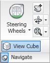 The Steering Wheels split button allows you to activate the Steering Wheel and choose the desired type.
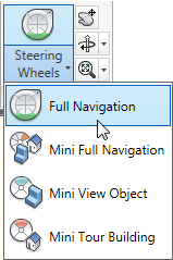 The drop-down list offers a choice between the Full Navigation Steering Wheel and three “mini” steering wheels; the main button initially defaults to Full Navigation, but will change to the most recently selected item from the list. The Pan Realtime command button executes the PAN command. The Orbit split button allows you to initiate one of three orbit types.
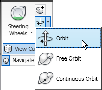 The drop-down includes the Orbit (3DORBIT), Free Orbit (3DFORBIT) and Continuous Orbit (3DCORBIT) commands. The last one chosen becomes the one activated by the main command button. The Zoom split button allows you to perform various ZOOM command options.
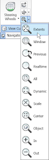 These are the same options available from the Zoom split button on the View panel (floating/Home tab), with the exception of omitting the Pan Realtime button, which is available separately on the Navigate panel. Click on the Navigate panel title bar to expand the panel and reveal the View Cube command button. This will only be active when your visual style is set to something other than 2D Wireframe; when active, it toggles the display of the View Cube on and off in all locations (main drawing window as well as other windows, such as the Object Viewer).
Appearance Panel
The Appearance Panel contains commands related to the drawing view and the appearance of objects.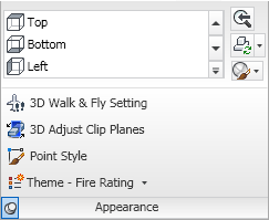 The View drop-down button displays a list of defined Views in the current drawing and allows you to restore one by selecting it.
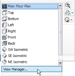 Use the up and down arrows at the right to scroll the list or use the drop-down button at the bottom right to see the defined Views in a drop-down list and expose the View Manager button, which opens the View Manager dialog (VIEW command). The Previous View command button runs the Previous option of the VIEW command. The Regenerate split button offers a choice of three regeneration-related commands: Regenerate Drawing (REGEN command), Regenerate Drawing and Viewports (REGENALL command) and AutoCAD-Architecture-specific Regenerate Model (OBJRELUPDATE command).
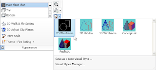
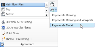 The main button always runs the Regenerate Drawing (REGEN) command. The Visual Styles drop-down button allows you to choose one of the currently defined visual styles in the drawing from an icon list (choice runs VSCURRENT command), save the current visual display as a named style (VSSAVE command) – provided that 2D Wireframe is not the current setting or open the Visual Styles Manager palette (VISUALSTYLES command).
 Expanding the panel by selecting the Appearance title bar provides access to four additional buttons. The 3D Walk & Fly Settings button opens the Walk and Fly Settings dialog (WALKFLYSETTINGS). The 3D Adjust Clip Planes button (3DCLIP) opens the Adjust Clippling Planes dialog. The Point Style button opens the Point Style dialog (DDPTYPE), allowing you to specify how Point objects appear on the screen. The Theme – Fire Rating drop-down button allows you to activate one of seven out-of-the-box Display Themes (DISPLAYTHEMEADD command).
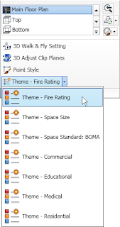 Each of the buttons on the drop-down runs a ribbon tool.
Coordinates Panel
The Coordinates Panel contains commands related to the User Coordinate System (UCS) and the UCS Icon.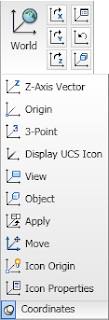 The World command button sets the UCS to “World,” aligning it with the World Coordinate System (WCS) (UCS command, World option). The X, Y and Z command buttons (left buttons on top, middle and bottom rows of the main panel) allow you to rotate the current UCS about the X-, Y- and Z-axes, respectively (UCS command; X, Y and Z options). The Named command button (top row, right button) opens the UCS dialog to the Named UCSs tab, allowing you to manage the defined user coordinate systems in the current drawing (UCSMAN). The Previous command button (middle row, right button) restores the previously current UCS for the current space (model or paper) – the last 10 in each space are retained (UCS command, Previous option). The Face command button aligns the UCS to a selected face on a 3D Solid (ALIGNUCSTOFACE). Selecting the Coordinates title bar expands the panel to reveal ten additional command buttons. The Z-Axis Vector command button moves the UCS origin to the first point selected and then rotates the UCS to have the Z-axis pass through the second point selected (UCS command, ZAxis option). The Origin command button moves the UCS origin point to a specified point (UCS command, Origin option). The 3-Point command button allows the user to establish a UCS by specifying an origin point, a point on the positive X-axis and a point on the positive Y-axis. (UCS command, 3point option). The Display UCS Icon command button toggles the visibility of the UCS icon in the current viewport (UCSICON command, ON and OFF options). The Apply command button applies the current UCS to a selected viewport (UCS command, Apply option). The Move command button moves a defined UCS (UCS command, Move option). The difference between the Origin and Move options is that Origin creates a new UCS with the specified origin point while Move redefines the current UCS, possibly affecting other viewports (unless the WCS is current, in which case Move also creates a new, unnamed UCS). The Icon Origin command button toggles between the two possible locations for the display of the UCS Icon – at the UCS Origin, if the current view permits, or always in the lower-left corner, even if the current view would permit (UCSICON command, Noorigin and Origin options). The Icon Properties command button opens the UCS Icon dialog, which allows you to control the appearance of the UCS Icon, including style, size and color.
Viewports Panel
The Viewports Panel contains commands related to both tiled (Model tab) and floating (Layout tab) viewports.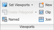 The Set Viewports drop-down button, only active when the Model tab is active, allows you to choose from a list of pre-defined tiled viewport configurations (VPORTS command).
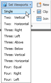 The Create Viewport split button, only active when a Layout tab is active, has two command buttons on the drop-down list: Create Polygonal, allowing you to draw a polygonal viewport by selecting vertex points (-VPORTS command, Polygonal option) and Create from Object, which allows you to select a closed polyline or a circle and create a viewport in that shape (-VPORTS command, Object option).
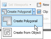 The last button selected on the drop-down list becomes the command executed by the main button. The Named command button opens the Viewports dialog to the Named tab, where saved viewport configurations can be selected (VPORTS). The New command button opens the Viewports dialog to the New Viewports tab and allows you to create a new named viewport configuration, or edit existing ones (VPORTS). The Clip command button, which can only be used in a Layout tab (TileMode 0), runs the VPCLIP command, which allows you to clip an existing floating viewport, either using an existing closed object (polyline or circle) as the clipping boundary or allowing you to draw a polygonal boundary on the fly. The Join command button, only active when the Model tab is current, allows you to join two adjacent tiled viewports, provided that the end result is a rectangle (-VPORTS command, Join option).
Face Effects Panel
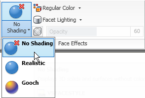
The Face Effects Panel contains commands related to the way faces of 3D objects display.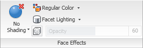 The VSFaceStyle split button allows you to choose type of shading used on the faces, no shading, realistic or gooch.
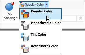
 The Color split button allows you to set a new value for VSColorMode: 0 (regular), 1 (monochrome), 2 (tint) or 3 (desaturate).
 The Lighting split button allows you to set a value for VSLightingQuality: 0 (facet), 1 (smooth) or 2 (smoothest).
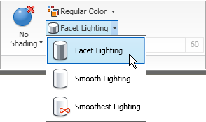 The main command button will change to the last option selected from the drop-down for all three of these split buttons. The X-Ray Effect command button toggles the sign of the value of VSFaceOpacity, turning the x-ray effect on and off. When it is on, the Opacity slider control allows you to change the level of transparency, from 0 to 100. On my computer, both 0 shows with full opacity, 1 is the most transparent and 100 is full opacity. For this to be effective, the current visual style needs to be a type that hides and face shading must be turned on.
Edge Effects Panel
The Edge Effects Panel contains commands related to the way edges of 3D objects display.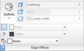 The VSEdges drop-down button allows you to select an edge display type: No Edges, Isolines or Facet Edges (VSEDGES). Supported edge types varies between the available visual style types.
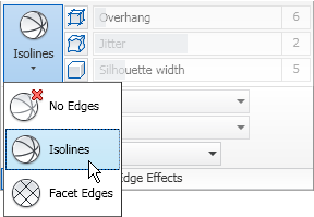 The Edge Overhang command button toggles on and off the effect that extends the edge lines of 3D solids and Mass Elements beyond the end of the edge (VSEDGEOVERHANG). The adjacent slider control allows you to control the amount of the overhang (VSEDGEOVERHANG). The Edge Jitter command button toggles on and off the effect that makes the edges of 3D Solids and Mass Elements “wavy” (VSEDGEJITTER). The adjacent slider control allows you to control the degree of waviness. The Silhouette Edges command button toggles on and off the display of a silhouette around the outer edges of 3D Solids and Mass Elements (VSSILHEDGES). The adjacent slider control allows you to control the width of the silhouette. Selecting the Edge Effects title bar expands the panel to reveal two toggles and three drop-down lists command buttons. When VSEdges is set to Facet Edges, the Obscurred Edges (VSOBSCUREDEDGES) and Intersection Edges (VSINTERSECTIONEDGES) become active, allowing you to toggle the display of obscurred (hidden) edges and the edges at the intersection of two 3D Solids or Mass Elements. When toggled on, the adjacent drop-down list becomes active, allowing you to set the color of obscured edges (VSOBSCUREDCOLOR) or intersection edges (VSINTERSECTIONCOLOR). The bottom drop-down allows you to set the color of visible edges of 3D Solids or Mass Elements (VSEDGECOLOR).
Windows Panel
The Windows Panel contains commands related to drawing and other interface windows.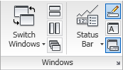 The Switch Windows drop-down button allows you to make any of the currently open drawings active, by selecting it from a list.
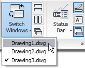 The Tile Horizontally, Tile Vertically and Cascade command buttons allow you to control the display of the currently open drawing windows (SYSWINDOWS). The Status Bar Options drop-down list allows you to control the display of icons and notifications on the Application Status Bar.
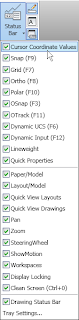 The Drawing Status Bar command button toggles the display of the Drawing Window Status Bar (STATUSBAR). The Text Window command button toggles the display of the AutoCAD Text Window (TXTSCR). The Command Line command button toggles the display of the Command Line Window (COMMANDLINE). Clicking on the arrow icon at the far right of the Windows title bar executes the OPTIONS command, opening the Options dialog to the Display tab.
The View tab is the fifth static (always available) tab provided in the out-of-the-box ACA CUI. The image below and all screen captures in this article are based on the shipping version.

Navigate Panel
The Navigate Panel contains commands related to navigating within a drawing.
 The Steering Wheels split button allows you to activate the Steering Wheel and choose the desired type.
 The drop-down list offers a choice between the Full Navigation Steering Wheel and three “mini” steering wheels; the main button initially defaults to Full Navigation, but will change to the most recently selected item from the list. The Pan Realtime command button executes the PAN command. The Orbit split button allows you to initiate one of three orbit types.
 The drop-down includes the Orbit (3DORBIT), Free Orbit (3DFORBIT) and Continuous Orbit (3DCORBIT) commands. The last one chosen becomes the one activated by the main command button. The Zoom split button allows you to perform various ZOOM command options.
 These are the same options available from the Zoom split button on the View panel (floating/Home tab), with the exception of omitting the Pan Realtime button, which is available separately on the Navigate panel. Click on the Navigate panel title bar to expand the panel and reveal the View Cube command button. This will only be active when your visual style is set to something other than 2D Wireframe; when active, it toggles the display of the View Cube on and off in all locations (main drawing window as well as other windows, such as the Object Viewer).
Appearance Panel
The Appearance Panel contains commands related to the drawing view and the appearance of objects.
 The View drop-down button displays a list of defined Views in the current drawing and allows you to restore one by selecting it.
 Use the up and down arrows at the right to scroll the list or use the drop-down button at the bottom right to see the defined Views in a drop-down list and expose the View Manager button, which opens the View Manager dialog (VIEW command). The Previous View command button runs the Previous option of the VIEW command. The Regenerate split button offers a choice of three regeneration-related commands: Regenerate Drawing (REGEN command), Regenerate Drawing and Viewports (REGENALL command) and AutoCAD-Architecture-specific Regenerate Model (OBJRELUPDATE command).
 The main button always runs the Regenerate Drawing (REGEN) command. The Visual Styles drop-down button allows you to choose one of the currently defined visual styles in the drawing from an icon list (choice runs VSCURRENT command), save the current visual display as a named style (VSSAVE command) – provided that 2D Wireframe is not the current setting or open the Visual Styles Manager palette (VISUALSTYLES command).
 Expanding the panel by selecting the Appearance title bar provides access to four additional buttons. The 3D Walk & Fly Settings button opens the Walk and Fly Settings dialog (WALKFLYSETTINGS). The 3D Adjust Clip Planes button (3DCLIP) opens the Adjust Clippling Planes dialog. The Point Style button opens the Point Style dialog (DDPTYPE), allowing you to specify how Point objects appear on the screen. The Theme – Fire Rating drop-down button allows you to activate one of seven out-of-the-box Display Themes (DISPLAYTHEMEADD command).
 Each of the buttons on the drop-down runs a ribbon tool.
Coordinates Panel
The Coordinates Panel contains commands related to the User Coordinate System (UCS) and the UCS Icon.
 The World command button sets the UCS to “World,” aligning it with the World Coordinate System (WCS) (UCS command, World option). The X, Y and Z command buttons (left buttons on top, middle and bottom rows of the main panel) allow you to rotate the current UCS about the X-, Y- and Z-axes, respectively (UCS command; X, Y and Z options). The Named command button (top row, right button) opens the UCS dialog to the Named UCSs tab, allowing you to manage the defined user coordinate systems in the current drawing (UCSMAN). The Previous command button (middle row, right button) restores the previously current UCS for the current space (model or paper) – the last 10 in each space are retained (UCS command, Previous option). The Face command button aligns the UCS to a selected face on a 3D Solid (ALIGNUCSTOFACE). Selecting the Coordinates title bar expands the panel to reveal ten additional command buttons. The Z-Axis Vector command button moves the UCS origin to the first point selected and then rotates the UCS to have the Z-axis pass through the second point selected (UCS command, ZAxis option). The Origin command button moves the UCS origin point to a specified point (UCS command, Origin option). The 3-Point command button allows the user to establish a UCS by specifying an origin point, a point on the positive X-axis and a point on the positive Y-axis. (UCS command, 3point option). The Display UCS Icon command button toggles the visibility of the UCS icon in the current viewport (UCSICON command, ON and OFF options). The Apply command button applies the current UCS to a selected viewport (UCS command, Apply option). The Move command button moves a defined UCS (UCS command, Move option). The difference between the Origin and Move options is that Origin creates a new UCS with the specified origin point while Move redefines the current UCS, possibly affecting other viewports (unless the WCS is current, in which case Move also creates a new, unnamed UCS). The Icon Origin command button toggles between the two possible locations for the display of the UCS Icon – at the UCS Origin, if the current view permits, or always in the lower-left corner, even if the current view would permit (UCSICON command, Noorigin and Origin options). The Icon Properties command button opens the UCS Icon dialog, which allows you to control the appearance of the UCS Icon, including style, size and color.
Viewports Panel
The Viewports Panel contains commands related to both tiled (Model tab) and floating (Layout tab) viewports.
 The Set Viewports drop-down button, only active when the Model tab is active, allows you to choose from a list of pre-defined tiled viewport configurations (VPORTS command).
 The Create Viewport split button, only active when a Layout tab is active, has two command buttons on the drop-down list: Create Polygonal, allowing you to draw a polygonal viewport by selecting vertex points (-VPORTS command, Polygonal option) and Create from Object, which allows you to select a closed polyline or a circle and create a viewport in that shape (-VPORTS command, Object option).
 The last button selected on the drop-down list becomes the command executed by the main button. The Named command button opens the Viewports dialog to the Named tab, where saved viewport configurations can be selected (VPORTS). The New command button opens the Viewports dialog to the New Viewports tab and allows you to create a new named viewport configuration, or edit existing ones (VPORTS). The Clip command button, which can only be used in a Layout tab (TileMode 0), runs the VPCLIP command, which allows you to clip an existing floating viewport, either using an existing closed object (polyline or circle) as the clipping boundary or allowing you to draw a polygonal boundary on the fly. The Join command button, only active when the Model tab is current, allows you to join two adjacent tiled viewports, provided that the end result is a rectangle (-VPORTS command, Join option).
Face Effects Panel
The Face Effects Panel contains commands related to the way faces of 3D objects display.
 The VSFaceStyle split button allows you to choose type of shading used on the faces, no shading, realistic or gooch.
 The Color split button allows you to set a new value for VSColorMode: 0 (regular), 1 (monochrome), 2 (tint) or 3 (desaturate).
 The Lighting split button allows you to set a value for VSLightingQuality: 0 (facet), 1 (smooth) or 2 (smoothest).
 The main command button will change to the last option selected from the drop-down for all three of these split buttons. The X-Ray Effect command button toggles the sign of the value of VSFaceOpacity, turning the x-ray effect on and off. When it is on, the Opacity slider control allows you to change the level of transparency, from 0 to 100. On my computer, both 0 shows with full opacity, 1 is the most transparent and 100 is full opacity. For this to be effective, the current visual style needs to be a type that hides and face shading must be turned on.
Edge Effects Panel
The Edge Effects Panel contains commands related to the way edges of 3D objects display.
 The VSEdges drop-down button allows you to select an edge display type: No Edges, Isolines or Facet Edges (VSEDGES). Supported edge types varies between the available visual style types.
 The Edge Overhang command button toggles on and off the effect that extends the edge lines of 3D solids and Mass Elements beyond the end of the edge (VSEDGEOVERHANG). The adjacent slider control allows you to control the amount of the overhang (VSEDGEOVERHANG). The Edge Jitter command button toggles on and off the effect that makes the edges of 3D Solids and Mass Elements “wavy” (VSEDGEJITTER). The adjacent slider control allows you to control the degree of waviness. The Silhouette Edges command button toggles on and off the display of a silhouette around the outer edges of 3D Solids and Mass Elements (VSSILHEDGES). The adjacent slider control allows you to control the width of the silhouette. Selecting the Edge Effects title bar expands the panel to reveal two toggles and three drop-down lists command buttons. When VSEdges is set to Facet Edges, the Obscurred Edges (VSOBSCUREDEDGES) and Intersection Edges (VSINTERSECTIONEDGES) become active, allowing you to toggle the display of obscurred (hidden) edges and the edges at the intersection of two 3D Solids or Mass Elements. When toggled on, the adjacent drop-down list becomes active, allowing you to set the color of obscured edges (VSOBSCUREDCOLOR) or intersection edges (VSINTERSECTIONCOLOR). The bottom drop-down allows you to set the color of visible edges of 3D Solids or Mass Elements (VSEDGECOLOR).
Windows Panel
The Windows Panel contains commands related to drawing and other interface windows.
 The Switch Windows drop-down button allows you to make any of the currently open drawings active, by selecting it from a list.
 The Tile Horizontally, Tile Vertically and Cascade command buttons allow you to control the display of the currently open drawing windows (SYSWINDOWS). The Status Bar Options drop-down list allows you to control the display of icons and notifications on the Application Status Bar.
 The Drawing Status Bar command button toggles the display of the Drawing Window Status Bar (STATUSBAR). The Text Window command button toggles the display of the AutoCAD Text Window (TXTSCR). The Command Line command button toggles the display of the Command Line Window (COMMANDLINE). Clicking on the arrow icon at the far right of the Windows title bar executes the OPTIONS command, opening the Options dialog to the Display tab.
January 09, 2010
Unexpected Automatic Offsets?
If you have ever used the out-of-the-box Door or Window tools with the Offset/Center option current, and wondered why the offset amount always defaults to 6" (Imperial tools), read on. My office's standard offset for Doors is 6" and that is usually the default value for me, so I would not have noticed. But thanks to this post in the Autodesk AutoCAD® Architecture Discussion Group, I discovered that the Door and Window tools on the Imperial Doors and Windows palettes in the Design Tool Palette Group have a "hidden" offset setting of 6". So even if your default offset is set to something else, when using the tool the value will be set to 6".
At first glance, it does not appear that there is any such setting. As shown below, the properties of the Hinged - Single Door Tool do not appear to include a preset offset value.
The Position along wall property is set to "--", which means that the current default value for that property (check the Properties palette after executing the tool to see what that is) will be used. If it is Offset/Center, then the value of the Automatic offset property will control what the offset value will be. But that property does not show up unless Position along wall is set to Offset/Center, in either the Properties palette or the Tool properties. So set the Position along wall property to Offset/Center in the Tool's properties, and the "hidden" Automatic offset property value will appear.
If you do not want this set to 6", set it to a different value, or use the dropdown list to choose "--" to allow the current default value to be the initial value after executing the tool. If you do not want Offset/Center to be the initial value for Position along wall, then reset that to "--" and click OK.
You will need to do that for all of the tools on the Doors and Windows palettes, if you do not want to have the 6" Automatic offset value. The good news is that the tools in the Design Tool Catalog - Imperial do not appear to have a hidden preset value assigned to them. I checked all of the Door tools, and a few of the Window and Door/Window Assembly tools, and the Automatic offset property was set to "--" in each. The generic tools on the Design tab also do not have a preset value.
Users of the US Metric out-of-the-box profile should not feel left out; there is a 125 mm preset offset on the Window tools and all of the Door tools except for the Overhead Sectional tool. I spot checked a few of the Design Tool Catalog - Metric and all of those did not have a preset Automatic offset. I spot checked a few of the out-of-the-box Door tools for the AutoCAD Architecture (UK) profile and none of those had a preset value.
At first glance, it does not appear that there is any such setting. As shown below, the properties of the Hinged - Single Door Tool do not appear to include a preset offset value.

The Position along wall property is set to "--", which means that the current default value for that property (check the Properties palette after executing the tool to see what that is) will be used. If it is Offset/Center, then the value of the Automatic offset property will control what the offset value will be. But that property does not show up unless Position along wall is set to Offset/Center, in either the Properties palette or the Tool properties. So set the Position along wall property to Offset/Center in the Tool's properties, and the "hidden" Automatic offset property value will appear.

If you do not want this set to 6", set it to a different value, or use the dropdown list to choose "--" to allow the current default value to be the initial value after executing the tool. If you do not want Offset/Center to be the initial value for Position along wall, then reset that to "--" and click OK.
You will need to do that for all of the tools on the Doors and Windows palettes, if you do not want to have the 6" Automatic offset value. The good news is that the tools in the Design Tool Catalog - Imperial do not appear to have a hidden preset value assigned to them. I checked all of the Door tools, and a few of the Window and Door/Window Assembly tools, and the Automatic offset property was set to "--" in each. The generic tools on the Design tab also do not have a preset value.
Users of the US Metric out-of-the-box profile should not feel left out; there is a 125 mm preset offset on the Window tools and all of the Door tools except for the Overhead Sectional tool. I spot checked a few of the Design Tool Catalog - Metric and all of those did not have a preset Automatic offset. I spot checked a few of the out-of-the-box Door tools for the AutoCAD Architecture (UK) profile and none of those had a preset value.
Subscribe to:
Posts (Atom)