- Start a new Generic Annotation Family. From the Application Menu - Big "R" in the upper left corner - choose New > Family. In the New Family - Select Template File dialog, navigate to the folder where you or your firm have placed the Annotation Family Templates, and choose Generic Annotation.rft.
- Determine how your Key Plan needs to function. I do not want to have to place the Key Plan family separately on each Sheet; I want it to be part of the title block family so that it need only be placed once, and will always be in the exact same position on each Sheet. I also do not want to set up a title block family type for each Key Plan option. I do not want to show a Key Plan on every sheet in the set, so I will need a Key Plan type that shows nothing at all. There will be plans that show the overall building, as well as larger scale plans showing only one of the two wings. I want a solid fill to show in the Key Plan indicating the area that is being shown on that drawing. I also want to be able to show the Key Plan outline graphics with no fill.
- Create the graphics for your Key Plan. You are going to have to figure this one out on your own. There does not appear to be a way to make use of any sort of graphics in a project file and transfer them to a family file. You can scale graphics inside the family, so you could draw the building outline in the family to scale and then scale it down to fit the area available in your title block for your Key Plan. As shown below, I created scaled-down outlines of the two wings of my building and then added text to identify the wings, filled regions with solid black fill for each wing, and the north arrow graphics. Keep in mind that the intersection of the two reference planes will be the initial insertion point for your Key Plan family and position your graphics accordingly.

- In order to be able to control the display of the various graphic components, I created three type-based Yes/No parameters in the Family Types dialog. The first is for the outline, text and north arrow graphics that will be on whenever a Key Plan is to be displayed, but off when no Key Plan is to be shown. I called this parameter Outline.
- On the Modify ribbon tab, on the Properties panel, select the Family Types tool.

- In the Family Types dialog, click on the Add button in the Parameters area at the lower right side.

- In the Parameter Properties dialog, in the Parameter Data area, enter the name for the parameter, change the Type of Parameter to Yes/No, select a parameter category under which to group the parameter - I used Graphics and select the Type toggle. Click OK to add the parameter and dismiss the Parameter Properties dialog.

- In the Family Types dialog, I cleared the check mark in the value column, so that the current condition will be to not display the graphics.
Repeat the previous sub-steps to add the remaining two parameters, SectorA and SectorB, for the filled regions associated with each building section. Other than the Name, the parameter attributes are the same as those for the Outline parameter. Uncheck the toggle in the value column for these as well.


- On the Modify ribbon tab, on the Properties panel, select the Family Types tool.
- With the Family Types dialog still open, create a family type for each display condition you want for your Key Plan, and turn on the appropriate visibility parameters for each type. In the example, I created five: No Key Plan (all parameters unchecked), Outline Only (only Outline parameter checked), Sector A (only Outline and SectorA checked), Sector B (only Outline and SectorB checked) and Sectors A-B (all three checked).
- In the Family Types dialog, select the New button in the Family Types area at the upper right.

- In the Name dialog, enter the name for the Family Type in the Name edit box and click OK to register the entry and dismiss the dialog.

- In the Family Types dialog, set the appropriate value (checked or unchecked) for the visibility parameters for this type. (For the No Key Plan type, leaving all unchecked is correct.)

- Repeat the preceding sub-steps to add the remaining Family Types needed for your Key Plan, setting the appropriate values for each type.

- In the Family Types dialog, select the New button in the Family Types area at the upper right.
- Select all of the graphic elements in your Key Plan that are to be associated with one of the parameters (in my example, I started with the Outline parameter, to which everything but the filled regions will be assigned). On the Properties palette, look for the Visible parameter, under the Graphics parameter group. If you do not see it, you likely selected an object, such as a Reference Plane or a Group, which does not have this parameter. Deselect these items. Select the button at the right side of the Visible parameter line. (In versions prior to 2011, do this from the Instance Properties dialog for the selected items.)

- In the Associate Family Parameter dialog, choose the appropriate Yes/No parameter (Outline, for the graphics selected on the first pass) and then click OK.

- Notice on the Properties palette, the Visible parameter and its value are now grayed out and the button at the right side displays an equals sign ("="). This indicates that the Visible parameter has been linked to another parameter, and cannot be edited directly. You can click on the button to verify (or edit) the chosen parameter.

- Repeat the previous three steps to assign the SectorA and SectorB Yes/No parameters to the visibility of the associated graphics (in my example, the filled regions). Note: If you have any Detail Groups within your Key Plan Graphics, as I did to collect the various parts of the north arrow graphics, you will need to edit the group to be able to assign the appropriate visibility parameters to the nested graphics within the Detail Group.
- At this point, your Key Plan family is complete. Save the family.
- Open the Title Block family into which you will place the Key Plan. Load your Key Plan family into the title block family. (One way, with the Key Plan family open and current, on any of the standard ribbon tabs, on the Family Editor panel, choose the Load into Project tool. If you have multiple potential target files, choose only your Title Block family in the dialog presented.)
- Your Title Block family should be set current and you should be prompted to insert an instance of the Key Plan family. If you are not seeing any "ghost" graphics of your Key Plan family near your cursor, check the Properties palette to see what the default family type is. Mine was set to No Key Plan, which has no visible graphics, so I got no ghost graphics to aid in initial placement. I changed it to Sectors A-B so that I could see all of the graphics.

- Adjust the location of your Key Plan family in your title block, if necessary.

- Select the placed instance of the Key Plan.
- On the Options Bar, click on the down arrow at the right of the Label drop-down and choose <Add parameter...> from the list.

- In the Parameter Properties dialog, in the Parameter Data area, give the new parameter a name; I used Key Plan. Choose a Group for the parameter; I used Graphics once again. Make this parameter an Instance type. This is crucial, as doing so will allow each instance of your title block to have a different family type displayed, which is what you want.

- On the Home ribbon tab, on the Properties panel, click the Family Types tool.
- You should see the Key Plan (or whatever your called yours) Label listed as a parameter under the Graphics group (or whatever group you chose). Set the value for the Label to your desired default Key Plan family type. This is the value that newly created (or newly updated) title block instances will use. I chose to set mine to No Key Plan. (If your Title Block family has several family types, you will want to do this for each Family Type. This only sets the default value; each instance can be changed to show a different Key Plan type because we made the Label an instance parameter. This avoids the need to create a separate Title Block family type for each Key Plan type.)

- Save your Title Block family file.
- Load or reload your Title Block family into a project. On a Sheet that has an instance of this Title Block family, select the instance.
- On the Properties palette, notice that, under the Graphics parameter group (or whatever parameter group you assigned to the Label applied to the Key Plan instance in your Title Block family), there is now a parameter called Key Plan, the value of which is a drop-down list of the family types you created in your Key Plan family. Choose the type you want to see for that particular Sheet.

Showing posts with label 2011. Show all posts
Showing posts with label 2011. Show all posts
October 19, 2011
Revit Key Plans - More Detail
It has come to my attention that my Revit Key Plans article can be hard to follow, particularly if you are not familiar with some of the concepts or procedures used. It was not intended to be a step-by-step tutorial, so I am providing this post to fill in some of the gaps and make it easier to follow along. This tutorial was prepared using Revit Architecture 2011; interface elements in other versions or releases may vary.


June 06, 2011
Revit Tip - Unwanted Linework Revisited
Thanks to a comment posted by Andrew to my Revit Tip - Masking Regions post, I am a step further along on my Revit journey. He correctly pointed out that the Linework tool would be a better choice for getting rid of the unwanted line.
On the Modify ribbon tab, on the View panel, click on the Linework tool, shown below in Revit Architecture 2011.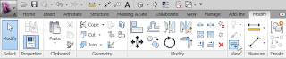 (As always, click on any reduced-size image to see the image full size. Use the Back button on your browser to return here.)
On the Modify|Linework ribbon tab, on the Line Style Panel, set the Line Style to <Invisible lines> in the Line Style drop down list.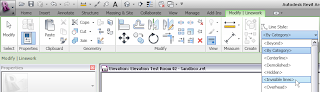 Now you can select the unwanted linework in the View in which you do not want to see it, and make it invisible with a single click. That is far more efficient than using a Masking Region to hide a single line.
If you change your mind later, you can restore the linework you made invisible by using the same Linework tool and setting the Line Style to <By Category> (or any other visible Line Style, if you do not want to use its default appearance).
On the Modify ribbon tab, on the View panel, click on the Linework tool, shown below in Revit Architecture 2011.
 (As always, click on any reduced-size image to see the image full size. Use the Back button on your browser to return here.)
On the Modify|Linework ribbon tab, on the Line Style Panel, set the Line Style to <Invisible lines> in the Line Style drop down list.
 Now you can select the unwanted linework in the View in which you do not want to see it, and make it invisible with a single click. That is far more efficient than using a Masking Region to hide a single line.
If you change your mind later, you can restore the linework you made invisible by using the same Linework tool and setting the Line Style to <By Category> (or any other visible Line Style, if you do not want to use its default appearance).
June 01, 2011
Update 2 for ACA 2011 Now Available
You can download Update 2 for AutoCAD® Architecture 2011 here.
According to the Readme, this Update is NOT cumulative; you will need to install Update 1 first, if you have not already done so. Be certain to read through the entire Readme before installing the update. According to the Readme, the following ACA items have been addressed in Update 2:
Annotation Scaling
Detail Components
Doors/Windows
Drawing Management
General UI
Multi-View Blocks
OpenLight
Structural Members
Walls
See my previous article, for the Updates addressed by Update 1.
According to the Readme, this Update is NOT cumulative; you will need to install Update 1 first, if you have not already done so. Be certain to read through the entire Readme before installing the update. According to the Readme, the following ACA items have been addressed in Update 2:
Annotation Scaling
- If two drawing units are different, the annotative blocks of the previous drawing version might be inserted with incorrect scale.
Detail Components
- Some detail components might not be added in the UK profile after installing Update 1.
Doors/Windows
- When you insert doors or windows evenly between the grid line or between walls, the elevation of the inserted doors or windows may result to a zero value.
Drawing Management
- Clearing the XML file in the current project may cause AutoCAD Architecture to crash.
- Renaming or renumbering the sheet in the Project Navigator may cause AutoCAD Architecture to crash.
General UI
- Accessing some tools from the Tool palettes may cause AutoCAD Architecture to crash.
Multi-View Blocks
- Exporting Multi-View Blocks to AutoCAD may result in incorrect sizes.
- In 3D shaded visual styles, a Multi-View Block created from circle with specified thickness might be drawn double.
OpenLight
- When the OpenLight plug-in is installed, the changes in the display configurations may not be maintained.
Structural Members
- When the start offset of a structural member is larger than its logical length, may cause AutoCAD Architecture to crash.
Walls
- Changing the view cube from parallel to perspective from the shortcut menu after selecting a wall may cause AutoCAD Architecture to crash.
- Clicking the Add Vertex button for some walls while editing in-place may cause AutoCAD Architecture to crash.
- Converting a 3D solid object created by extruding profile along a certain path to wall may cause irregular geometry.
- If the walls are with separate wall components which have bottom elevation offset, these walls may not display correctly in plan view.
See my previous article, for the Updates addressed by Update 1.
January 19, 2011
ACA Section Tail Scaling
Here is a heads up to anyone who may be placing Section Marks with "tails" in Model Space from a Layout through a Viewport. The AecCallout command has an apparent defect in the way it creates the anonymous block for the tail. It works fine when placing the Section Mark from the "Model tab" (when "Model" or TILEMODE 1, rather than a "Layout" or TILEMODE 0 is current). It also works correctly when in a Layout and working through a Viewport when the scale of the Viewport is the same as the scale set for "Model".
But if the Viewport's scale is not the same as the "Model" scale, then the anonymous block that gets created is improperly sized. The correct annotation scale (matching that of the Viewport) is applied to the tail block, but the improper size of the block definition results in the final block displaying the same size as one placed through a Viewport that has the same scale as "Model".
To avoid this problem, you can do one of the following:
The block at the other end of the Section Mark, displaying the Section Number and, possibly, the Sheet Number, does not suffer from this defect.
But if the Viewport's scale is not the same as the "Model" scale, then the anonymous block that gets created is improperly sized. The correct annotation scale (matching that of the Viewport) is applied to the tail block, but the improper size of the block definition results in the final block displaying the same size as one placed through a Viewport that has the same scale as "Model".
To avoid this problem, you can do one of the following:
- Place all callouts from the "Model tab" (TILEMODE 1), setting the desired drawing scale prior to placement.
- Remember to switch to "Model"/TILEMODE 1 and set the drawing scale to match that of the Viewport and then switch back to the Layout.
- Place the callout in the Viewport and then, after placement, change X-scale factor of the block to get it to be the right size [Viewport scale factor/Model scale factor]. The anonymous block created has uniform scaling, so the change to the X-scale factor will be applied to the Y- and Z-scale factors as well.
The block at the other end of the Section Mark, displaying the Section Number and, possibly, the Sheet Number, does not suffer from this defect.
November 26, 2010
ACA 2011 - Opening Location Changes - Part 4
First Post in Series: ACA 2011 - Opening Location Changes - Part 1
Previous Post in Series: ACA 2011 - Opening Location Changes - Part 3
To wrap up this series on opening location changes in AutoCAD® Architecture 2011, we will look at the ribbon tools that have been provided to make using them somewhat less tedious. Several choices have been combined into one ribbon tool, reducing the number of steps needed when working "manually", as presented in the previous articles.
These tools are located on the Wall contextual ribbon tab, on the General panel, so in order to access them, you will need to select a Wall. The Door and Window tools are now split buttons, and if you click on the lower half of the tool (the part with the arrow icon), you will get a list of tools from which to choose. For Doors, these tools are Door (DOORADD command), Offset from Grid Line (DOORADD GRID YES POSITION OFFSET command), Center between Grid Lines (DOORADD GRID YES POSITION CENTER command), Evenly between Grid Lines (DOORADD GRID YES MULTIPLE command), Evenly between walls (DOORADD GRID NO MULTIPLE command) and Entire Wall (DOORADD WIDTH MAXIMIZE command).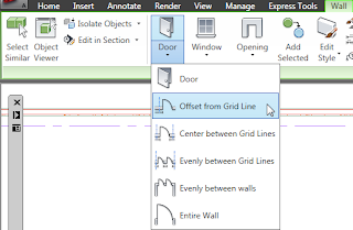 The same options are available for Windows (substitute the WINDOWADD command for the DOORADD command).
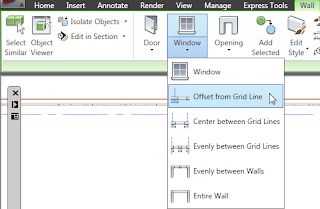 Since Openings and Door/Window Assemblies do not offer the relative to grid line or multiple options, there are no additional choices on the Opening-Door/Window Assembly tool.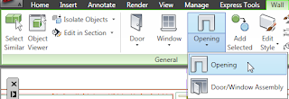
One thing to keep in mind is that when you choose one of the Door or Window tools from the flyout other than the "plain" Door (DOORADD) or Window (WINDOWADD) tool, some of the options associated with that tool will become your new default options. The Relative to grid and Position properties will retain the selected option. The Multiple insert property will maintain a default value of No.
I personally do not see much use for the Entire Wall tools, particularly with respect to Doors, but if you need to fill an entire Wall segment with a Door or Window, the option is there. I would be more likely to want to use the Entire Wall option with a Door/Window Assembly, but that is not an option for Door/Window Assemblies.
Previous Post in Series: ACA 2011 - Opening Location Changes - Part 3
To wrap up this series on opening location changes in AutoCAD® Architecture 2011, we will look at the ribbon tools that have been provided to make using them somewhat less tedious. Several choices have been combined into one ribbon tool, reducing the number of steps needed when working "manually", as presented in the previous articles.
These tools are located on the Wall contextual ribbon tab, on the General panel, so in order to access them, you will need to select a Wall. The Door and Window tools are now split buttons, and if you click on the lower half of the tool (the part with the arrow icon), you will get a list of tools from which to choose. For Doors, these tools are Door (DOORADD command), Offset from Grid Line (DOORADD GRID YES POSITION OFFSET command), Center between Grid Lines (DOORADD GRID YES POSITION CENTER command), Evenly between Grid Lines (DOORADD GRID YES MULTIPLE command), Evenly between walls (DOORADD GRID NO MULTIPLE command) and Entire Wall (DOORADD WIDTH MAXIMIZE command).
 The same options are available for Windows (substitute the WINDOWADD command for the DOORADD command).
 Since Openings and Door/Window Assemblies do not offer the relative to grid line or multiple options, there are no additional choices on the Opening-Door/Window Assembly tool.
One thing to keep in mind is that when you choose one of the Door or Window tools from the flyout other than the "plain" Door (DOORADD) or Window (WINDOWADD) tool, some of the options associated with that tool will become your new default options. The Relative to grid and Position properties will retain the selected option. The Multiple insert property will maintain a default value of No.
I personally do not see much use for the Entire Wall tools, particularly with respect to Doors, but if you need to fill an entire Wall segment with a Door or Window, the option is there. I would be more likely to want to use the Entire Wall option with a Door/Window Assembly, but that is not an option for Door/Window Assemblies.
November 16, 2010
Aubin Academy Books for ACA and AMEP 2011

The 2011 edition of Paul Aubin's books for AutoCAD® Architecture and AutoCAD® MEP are now available. You can read more about it in this article in Paul's blog (click on the BOOKS link at the top of his site to find more detailed information on any of his books).
November 12, 2010
ACA 2011 - Opening Location Changes - Part 3
First Post in Series: ACA 2011 - Opening Location Changes - Part 1
Previous Post in Series: ACA 2011 - Opening Location Changes - Part 2
Another new feature is the ability to place multiple openings at once. As with the relative to grid feature, the multiple openings feature only applies to Doors and Windows. The openings can either be spaced evenly on the selected segment or centered on the segment with a fixed offset between the openings. Relative to grid can be set to either No (use Wall Ends or intersecting Walls) or Yes (use intersection Grid lines) to determine the Wall segment over which the multiple openings will be placed. In the images here, a Window object will be placed with Relative to grid set to Yes.
The sequence of picks and settings is somewhat fussy, so pay close attention to the following. If you prefer, you can also read the Command: line prompts and set the property values there using the command options.
Next Post in Series: ACA 2011 - Opening Location Changes - Part 4
Previous Post in Series: ACA 2011 - Opening Location Changes - Part 2
Another new feature is the ability to place multiple openings at once. As with the relative to grid feature, the multiple openings feature only applies to Doors and Windows. The openings can either be spaced evenly on the selected segment or centered on the segment with a fixed offset between the openings. Relative to grid can be set to either No (use Wall Ends or intersecting Walls) or Yes (use intersection Grid lines) to determine the Wall segment over which the multiple openings will be placed. In the images here, a Window object will be placed with Relative to grid set to Yes.
The sequence of picks and settings is somewhat fussy, so pay close attention to the following. If you prefer, you can also read the Command: line prompts and set the property values there using the command options.
- Start WindowAdd command by whatever means you normally do (eg, tool palette tool).
- Select a Wall in the drawing.
- On the Properties palette, on the Design tab, in the Dimensions category, set the desired Width and Height (or choose the desired Standard size).
- In the Location category, set Relative to grid to the desired value. The value of the Position property does not matter.
- Set the Multiple insert property to Yes. Notice that the Command line prompt now asks you to select a Wall segment. Yes, you will need to select a Wall again, but this time you need to pick the exact segment you want. As you hover over a Wall, notice the solid red line that shows up, in addition to the Wall highlight (assuming you have highlighting while selecting turned on).
 The red line defines the extents of the Wall segment over which the multiple openings will be inserted. When you have the segment you want, select the Wall
 - You can now set the number of openings to insert, either in the Number to insert property or at the Command: line prompt. The initial default value will be the maximum number of openings that can be fit along the selected segment. For the example here, the default was 6, but I changed it to 3.
- In the Location category, choose the desired value for the Spacing property, Equally or Offset.
- If you choose Equally, then the difference between the segment length and the sum of the Widths of the openings, will be divided into equal segments, at the beginning, between each opening and at the end.
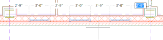
- If you choose Offset, another property, Offset multiples, appears, allowing you to specify the distance between the openings. The entire array is centered on the segment, so the additional space is divided equally to each side.

- If you choose Equally, then the difference between the segment length and the sum of the Widths of the openings, will be divided into equal segments, at the beginning, between each opening and at the end.
- Finally, left click in the drawing area to accept the arrangement ghosted on the screen and continue on with the command in progress (WindowAdd in the example). The Multiple insert property will reset to no, so if you want to add another set of multiple openings of the same object, you will need to start the sequence above from Step 3 (Step 5 if the opening size and Relative to grid are to remain the same).


Next Post in Series: ACA 2011 - Opening Location Changes - Part 4
October 16, 2010
ACA 2011 - Opening Location Changes - Part 2
First Post in Series: ACA 2011 - Opening Location Changes - Part 1
The first post covered the splitting of the Offset/Center option into separate Offset and Center options when placing a opening (Door, Window, Door/Window Assembly or Opening) object in a Wall, and showed how that worked for a Door, using Wall ends or intersecting Walls to define the Wall segments to which the Offset or Center applies. In this post, we will look at the newly added "Relative to grid" property, which only applies to Doors and Windows.
When set to "No", Walls are used to define the segments, as in previous releases. When set to "Yes",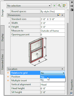 AutoCAD® Architecture will use grid lines that intersect the Wall to determine the Wall Segment over which the Center or Offset will be applied. In the image below, the Center option has been selected, and, as you can see, the Window is centered between the two grid lines crossing the Wall, ignoring the intersecting Wall.*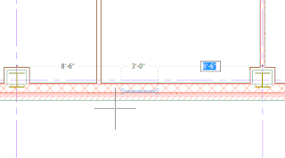
The Offset option works in a similar fashion, using intersecting Grid lines to define the offset points.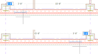
As mentioned in the first post, any type of Grid can be used - Ceiling Grids, Column Grids or Layout Grids - provided that the Grid is visible in the currently active Display Representation Set. Ceiling Grids are less likely candidates, given their usually small cell dimensions.
The next post will examine the new multiple option when placing openings.
Next Post in Series: ACA 2011 - Opening Location Changes - Part 3
* - For the purposes of this article, I extended the Column Grid by one additional bay, so that the Column Grid lines perpendicular to the exterior Wall would actually cross the Wall. If I had not done so, ACA would have found no grid lines and would have acted on the entire length of the Wall instead. Adding Grid Labels does not change anything, as what appear to be Grid Line extensions are actually the Anchor objects that attach the grid bubble Multi-View Blocks to the Grid, masquerading as Grid Lines. This is a major drawback for this feature in my opinion, as I can see wanting to have multiple, evenly spaced openings in a structural bay on an exterior Wall to be relatively common, but do not expect to be using this on interior Walls very often, if ever.
The first post covered the splitting of the Offset/Center option into separate Offset and Center options when placing a opening (Door, Window, Door/Window Assembly or Opening) object in a Wall, and showed how that worked for a Door, using Wall ends or intersecting Walls to define the Wall segments to which the Offset or Center applies. In this post, we will look at the newly added "Relative to grid" property, which only applies to Doors and Windows.
When set to "No", Walls are used to define the segments, as in previous releases. When set to "Yes",
 AutoCAD® Architecture will use grid lines that intersect the Wall to determine the Wall Segment over which the Center or Offset will be applied. In the image below, the Center option has been selected, and, as you can see, the Window is centered between the two grid lines crossing the Wall, ignoring the intersecting Wall.*
The Offset option works in a similar fashion, using intersecting Grid lines to define the offset points.

As mentioned in the first post, any type of Grid can be used - Ceiling Grids, Column Grids or Layout Grids - provided that the Grid is visible in the currently active Display Representation Set. Ceiling Grids are less likely candidates, given their usually small cell dimensions.
The next post will examine the new multiple option when placing openings.
Next Post in Series: ACA 2011 - Opening Location Changes - Part 3
* - For the purposes of this article, I extended the Column Grid by one additional bay, so that the Column Grid lines perpendicular to the exterior Wall would actually cross the Wall. If I had not done so, ACA would have found no grid lines and would have acted on the entire length of the Wall instead. Adding Grid Labels does not change anything, as what appear to be Grid Line extensions are actually the Anchor objects that attach the grid bubble Multi-View Blocks to the Grid, masquerading as Grid Lines. This is a major drawback for this feature in my opinion, as I can see wanting to have multiple, evenly spaced openings in a structural bay on an exterior Wall to be relatively common, but do not expect to be using this on interior Walls very often, if ever.
October 09, 2010
ACA 2011 - Opening Location Changes - Part 1
One item that has changed in the 2011 release* of AutoCAD® Architecture is the way that openings (Doors, Windows, Door/Window Assemblies and Openings) are placed in Walls. Instead of a choice between Unconstrained and Offset/Center, you now have three choices: Unconstrained, Offset and Center. While you may initially miss having Offset and Center available at the same time, I am told that these needed to be split into separate options, in order to enable the new "Space Evenly" options that allow you to place multiple, evenly spaced, Doors or Windows in one operation. Also new is the choice to have the offset or centering boundaries be Walls (as before) or Grid Lines. Any type of grid (Layout, Column, Ceiling) will work, although Column and Layout will most likely be the ones most often used. I will take a look at these new options in the next few posts.
You will want to have your Properties palette open when placing openings in order to have control over the placement. (You can also make use of Command-line prompts or Dynamic Input, although the latter is failing to display a list of Position options for me.) Look on the Design tab, under the Location category, which is at the bottom of the tab. Notice that the first three properties have an eight-pointed asterisk icon at the left side. That indicates that these properties are only available at the time of object creation.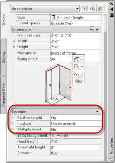 Note that until you select a Wall (the first prompt of the DoorAdd command), the Multiple insert property will be grayed out and inactive. This post will focus on placing a single opening relative to Walls. With Relative to grid set to no, the Position setting will be relative to Walls. As in previous versions, setting Postion to unconstrained allows you to move your cursor to the place where you want the Door and click to place it - or, for more precision, you can type a value into the Dynamic Dimension Input, if enabled. You may also want to turn off any running Object Snaps when placing openings.
Changing the Position property to Offset in the Properties palette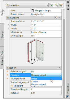 will add a new property, Automatic offset,
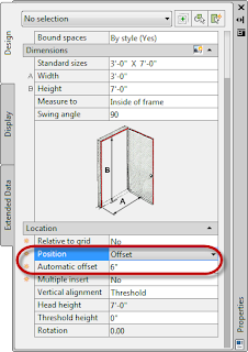 in which you specify the distance from which the Door is to be offset from the Wall end or intersecting Wall. This should be be familiar, as it worked the same way before, only now you can only place an offset Door, rather than being able to offset or center the Door, depending upon your cursor position. With the Position property set to Offset, the Door can only be placed offset from the Wall End or from an intersecting Wall.

Setting the Position property to Center will remove the Automatic offset property, if it was previously present.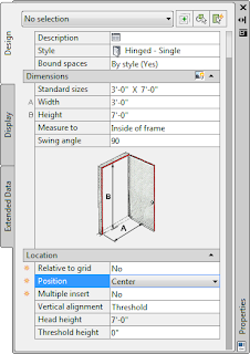 With this Postion setting, the Door will be constrained to the middle of the Wall or Wall segment.
So far, the only new thing has been the splitting of Offset and Center into separate options. The next post will look at the new Relative to grid option.
Next Post in Series: ACA 2011 - Opening Location Changes - Part 2
* - Subscribers who installed the 2010 Subscription Advantage Pack have already seen these changes. The ribbon tools associated with them have been integrated into the ACA 2011 ribbon, rather than being on a separate ribbon tab, as was the case with the Subscription Advantage Pack.
You will want to have your Properties palette open when placing openings in order to have control over the placement. (You can also make use of Command-line prompts or Dynamic Input, although the latter is failing to display a list of Position options for me.) Look on the Design tab, under the Location category, which is at the bottom of the tab. Notice that the first three properties have an eight-pointed asterisk icon at the left side. That indicates that these properties are only available at the time of object creation.
 Note that until you select a Wall (the first prompt of the DoorAdd command), the Multiple insert property will be grayed out and inactive. This post will focus on placing a single opening relative to Walls. With Relative to grid set to no, the Position setting will be relative to Walls. As in previous versions, setting Postion to unconstrained allows you to move your cursor to the place where you want the Door and click to place it - or, for more precision, you can type a value into the Dynamic Dimension Input, if enabled. You may also want to turn off any running Object Snaps when placing openings.
Changing the Position property to Offset in the Properties palette
 will add a new property, Automatic offset,
 in which you specify the distance from which the Door is to be offset from the Wall end or intersecting Wall. This should be be familiar, as it worked the same way before, only now you can only place an offset Door, rather than being able to offset or center the Door, depending upon your cursor position. With the Position property set to Offset, the Door can only be placed offset from the Wall End or from an intersecting Wall.
Setting the Position property to Center will remove the Automatic offset property, if it was previously present.
 With this Postion setting, the Door will be constrained to the middle of the Wall or Wall segment.
So far, the only new thing has been the splitting of Offset and Center into separate options. The next post will look at the new Relative to grid option.
Next Post in Series: ACA 2011 - Opening Location Changes - Part 2
* - Subscribers who installed the 2010 Subscription Advantage Pack have already seen these changes. The ribbon tools associated with them have been integrated into the ACA 2011 ribbon, rather than being on a separate ribbon tab, as was the case with the Subscription Advantage Pack.
October 02, 2010
The Aubin Academy Series Books
Those of you who have enjoyed Paul Aubin's books may be glad to know that the first of his books for the 2011 releases, The Aubin Academy Master Series: Revit® Architecture 2011, is now out. The AutoCAD® Architecture 2011 book, with which I assisted, is due out October 27, as is the AutoCAD® MEP book. The Revit® MEP 2011 book is expected in December. You can read more about this year's books and the rebranding in Paul's blog.
September 28, 2010
ACA 2011 Update 1
Update 1 for AutoCAD® Architecture 2011 is now available, here.
The Readme (be sure to read it, especially the parts on installation and backing up of your custom files) indicates that the following ACA issues have been resolved:
3D Modeling
Curtain Walls
Dimensions
Drawing Management
General UI
Help
IFC
Materials
Modify
Performance
Renovation
Sections
Slabs
Walls
A number of AutoCAD fixes are also listed in the Readme.
The Readme (be sure to read it, especially the parts on installation and backing up of your custom files) indicates that the following ACA issues have been resolved:
3D Modeling
- Components whose display has been turned off are shown on converting an AEC object to a 3D Solid.
Curtain Walls
- Custom model components in a curtain wall may display incorrect material assignments in different display configurations in 3D views.
Dimensions
- Associative dimensions may not update when walls are moved.
Drawing Management
- Redefining an existing model space view causes AutoCAD Architecture to crash.
General UI
- AutoCAD Architecture may crash on launching the Style Manager.
Help
- Third-party applications based on AutoCAD Architecture cannot access their Help files through the application.
IFC
- Some roofs may change position after executing the IFCEXPORT command.
Materials
- The MATERIALLIST command reports the volume of only the first object in a multiple selection.
Modify
- AutoCAD Architecture may crash while trimming entities.
Performance
- Sometimes memory usage increases when switching back and forth between the tabs of the Properties Palette.
Renovation
- A wall with display overrides displays incorrectly when modified in the renovation mode.
Sections
- Creating a horizontal section may cause AutoCAD Architecture to crash.
Slabs
- No style information is available in the Properties Palette for a slab created by applying the properties of the Slab tool to linework and walls.
Walls
- Trimming a wall may cause doors and windows in the wall to move or disappear.
- Walls that clean up correctly in a previous version may not clean up correctly in AutoCAD Architecture 2011.
- Wall cleanup EIP functions such as Merge, Subtract, Fillet, and Chamfer do not work in a custom UCS.
A number of AutoCAD fixes are also listed in the Readme.
September 04, 2010
Hatch Editing With Grips - 2010 & Later
Here is an AutoCAD® feature that has been around since the 2010 release, and now that I am using that in the office, I thought it worth a mention, given how easy it makes updating non-associative hatches - even those created in previous releases. Given the problems associative hatches can have when an external reference or an AEC object is part of the boundary (when opening the file, the hatch often tries to resolve itself before all of the bounding objects have been loaded and resolved), I had taken to drawing polyline boundaries on a non-plotting layer and making hatches associative to that, so that I could edit the boundary easily should the area of hatch need to be changed in the future. Having been on the 2004 release for quite some time for production work, I was not able to take advantage of the ability to generate a boundary of an existing, non-associative hatch and make the hatch associative to it. The new grip editing feature makes this additional step unecessary.
To demonstrate the grip editing feature, I have created a square, non-associative hatch (and deleted the original bounding polyline), and drawn another polyline, to which I will extend the hatch, using grip edits.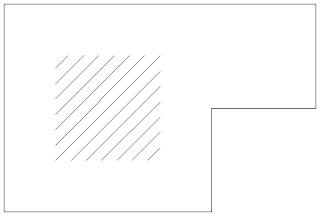
Selecting the hatch reveals a number of grips. The center grip allows you to move the entire hatch, and was present in releases previous to 2010. The Vertex and Edge grips are new in 2010 (and are also present in 2011). ACA users should be familiar with hovering the cursor over a grip to get a tooltip, possibly listing options, and that technique works here as well.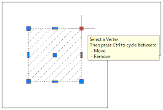 Hovering over a square grip at the perimeter of the hatch (Vertex) reveals that selecting that grip will allow you to initially move the Vertex to a new location, and pressing the CTRL key will cycle to the Remove option, allowing you to delete the Vertex.
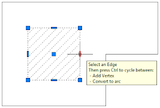 Hovering over a rectangular Edge grip on a straight segment at the hatch perimeter shows that the intial action on selecting the grip will be to add a new Vertex, and that pressing the CTRL key will cycle to converting that Edge to an arc.
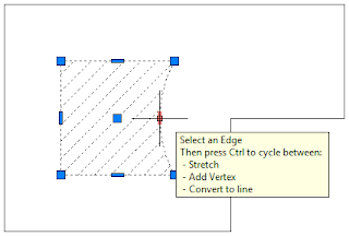 Hovering over the rectangular grip of an arc Edge of a hatch indicates that the initial action is to stretch the arc and that you can use the CTRL key to cycle to add a new Vertex and then to convert the arc to a line.
ACA users that have used grip edits on AEC objects will have to remind themselves that the Edge grips can NOT be used to stretch a straight segement, as they can for AEC Polygons.
To make the square hatch fill the drawn polyline with grip editing, use the Move option to relocate the four existing Vertices to Vertices on the polyline.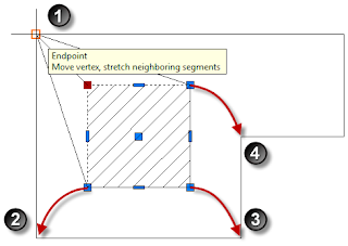 To fill in the remainder, select the Edge grip that is not on a segment of the polyline and use the Add Vertex mode to add a fifth...
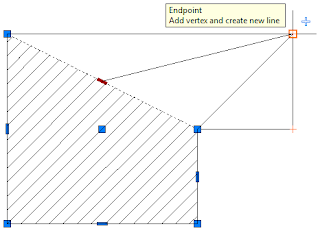 ...and sixth Vertex...
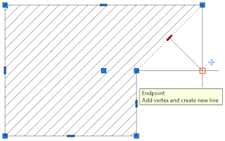 ...filling the polyline.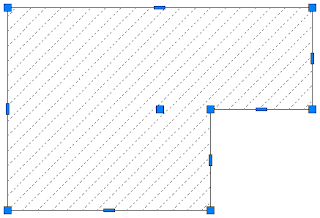
You can, of course, accomplish this simple edit in one step, by selecting the original square hatch, right clicking, choosing Set Boundary from the context menu and then picking the polyline.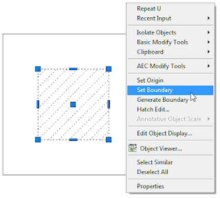 But in a typical drawing, where you have a lot more linework and, perhaps, several adjoining hatches, and where the linework defining the hatch edges is not a single polyline, I have found grip editing of hatches to be a very useful feature, and one that has virtually eliminated the need to delete an existing hatch and then rehatch the area.
To demonstrate the grip editing feature, I have created a square, non-associative hatch (and deleted the original bounding polyline), and drawn another polyline, to which I will extend the hatch, using grip edits.

Selecting the hatch reveals a number of grips. The center grip allows you to move the entire hatch, and was present in releases previous to 2010. The Vertex and Edge grips are new in 2010 (and are also present in 2011). ACA users should be familiar with hovering the cursor over a grip to get a tooltip, possibly listing options, and that technique works here as well.
 Hovering over a square grip at the perimeter of the hatch (Vertex) reveals that selecting that grip will allow you to initially move the Vertex to a new location, and pressing the CTRL key will cycle to the Remove option, allowing you to delete the Vertex.
 Hovering over a rectangular Edge grip on a straight segment at the hatch perimeter shows that the intial action on selecting the grip will be to add a new Vertex, and that pressing the CTRL key will cycle to converting that Edge to an arc.
 Hovering over the rectangular grip of an arc Edge of a hatch indicates that the initial action is to stretch the arc and that you can use the CTRL key to cycle to add a new Vertex and then to convert the arc to a line.
ACA users that have used grip edits on AEC objects will have to remind themselves that the Edge grips can NOT be used to stretch a straight segement, as they can for AEC Polygons.
To make the square hatch fill the drawn polyline with grip editing, use the Move option to relocate the four existing Vertices to Vertices on the polyline.
 To fill in the remainder, select the Edge grip that is not on a segment of the polyline and use the Add Vertex mode to add a fifth...
 ...and sixth Vertex...
 ...filling the polyline.
You can, of course, accomplish this simple edit in one step, by selecting the original square hatch, right clicking, choosing Set Boundary from the context menu and then picking the polyline.
 But in a typical drawing, where you have a lot more linework and, perhaps, several adjoining hatches, and where the linework defining the hatch edges is not a single polyline, I have found grip editing of hatches to be a very useful feature, and one that has virtually eliminated the need to delete an existing hatch and then rehatch the area.
July 26, 2010
Frozen Ribbon
No, it is not a new way to beat the summer heat (my apologies to readers in the southern hemisphere, who may be more interested in a way to stay warm, but this has been a particularly brutal summer here in Philadelphia); it is a frequently reported occurrence in AutoCAD® Architecture 2010 and 2011. Often triggered by the use of the MTEXT command, the freeze occurs if you have more than one CUIX file loaded and two or more each have a contextual ribbon tab (such as the Text Editor tab triggered by the MTEXT or MTEDIT commands) that is triggered by the same command or object selection.
This most frequently happens when both the ACA.cuix and ACAD.cuix files are loaded simultaneously, often so that an ACA user can have access to elements in the ACAD.cuix file that are not part of the ACA.cuix file. Unfortunately, loading both as they are, out-of-the-box, will result in having multiple contextual ribbon tabs for the same triggering action.
The solution is to either not load both at the same time, or, if you must have access to items in both, to create a custom CUIX file that has the items you want from the ACAD.cuix file, but does not have the contextual ribbon tabs (or at least not any that overlap those in the ACA.cuix file). You will need to decide whether it is easier to make a copy of the ACAD.cuix file under another name, and remove the overlapping contextual ribbon tabs -OR- set up a new CUIX file and transfer only the items you want/need from the ACAD.cuix file.
This most frequently happens when both the ACA.cuix and ACAD.cuix files are loaded simultaneously, often so that an ACA user can have access to elements in the ACAD.cuix file that are not part of the ACA.cuix file. Unfortunately, loading both as they are, out-of-the-box, will result in having multiple contextual ribbon tabs for the same triggering action.
The solution is to either not load both at the same time, or, if you must have access to items in both, to create a custom CUIX file that has the items you want from the ACAD.cuix file, but does not have the contextual ribbon tabs (or at least not any that overlap those in the ACA.cuix file). You will need to decide whether it is easier to make a copy of the ACAD.cuix file under another name, and remove the overlapping contextual ribbon tabs -OR- set up a new CUIX file and transfer only the items you want/need from the ACAD.cuix file.
June 27, 2010
Selection Cycling
As mentioned in the AutoCAD Improvements section of my AutoCAD Architecture 2011 Overview post, I found the Selection Cycling feature quite handy. Here is a look at how it works.
Activation of the Selection Cycling feature is controled by a new toggle on the Application Status Bar, and the SELECTIONCYCLING system variable. SELECTIONCYCLING is stored in the registry (so is not drawing-dependent) and has three main values, as noted in the online Help:
0 - Off
1 - On (the list dialog does not display)
2 - On (the list dialog displays the selected objects that you can cycle through)
What the Help fails to mention is that the Application Status Bar toggle can introduce two other values:
-1 - Off, but previous value was "1" and, when toggled back on, will reset to "1"
-2 - Off, but previous value was "2" and, when toggled back on, will reset to "2"
If you manually set SELECTIONCYCLING to "0" to turn it off, clicking on the Application Status Bar toggle will set the value to "2". With selction cycling active, when your cursor hovers over a spot where there are multiple objects, you will see an overlapping rectangle icon adjacent to the cursor.
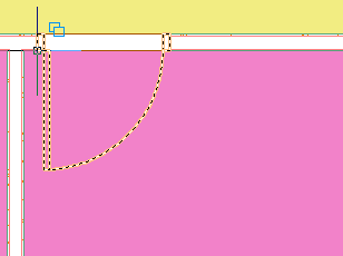 With SELECTIONCYCLING set to 1, you will get the legacy behavior for cycling through multiple items near your pick point. As indicated in the online Help:
1. At the Select Objects prompt, hold down Shift + Spacebar. Click as near as possible to the object you want.
2. Keep clicking until the object you want is highlighted.
3. Press Enter to select the object.
Note: If selection preview is turned on, you can cycle through the objects by rolling over the object on top to highlight it, and pressing and holding Shift and then pressing Spacebar continuously. When the required object is highlighted, left-click to select it.
With SELECTIONCYCLING set to 2, a left click will call up the Selection dialog, listing all of the objects that are selectable at the click point, by object type. If you move your cursor over to the dialog and hover over an item on the list, it will be highlighted both on the list and in the drawing.
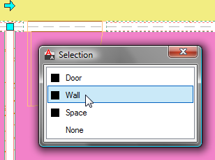
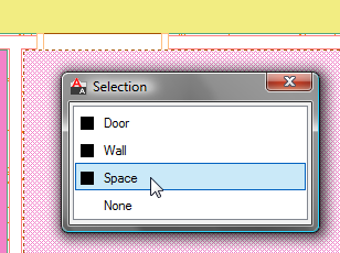 When the object you want is highlighted, a left click on the item in the dialog dismisses the dialog and selects that item. If you decide against selecting any of the offered items, choose None at the bottom of the list.
You will probably not want to have this turned on all of the time, but for those times when you need to select an item in heavy traffic, toggling Selection Cycling on can be quite effective.
Activation of the Selection Cycling feature is controled by a new toggle on the Application Status Bar, and the SELECTIONCYCLING system variable. SELECTIONCYCLING is stored in the registry (so is not drawing-dependent) and has three main values, as noted in the online Help:
0 - Off
1 - On (the list dialog does not display)
2 - On (the list dialog displays the selected objects that you can cycle through)
What the Help fails to mention is that the Application Status Bar toggle can introduce two other values:
-1 - Off, but previous value was "1" and, when toggled back on, will reset to "1"
-2 - Off, but previous value was "2" and, when toggled back on, will reset to "2"
If you manually set SELECTIONCYCLING to "0" to turn it off, clicking on the Application Status Bar toggle will set the value to "2".
 With selction cycling active, when your cursor hovers over a spot where there are multiple objects, you will see an overlapping rectangle icon adjacent to the cursor.
 With SELECTIONCYCLING set to 1, you will get the legacy behavior for cycling through multiple items near your pick point. As indicated in the online Help:
1. At the Select Objects prompt, hold down Shift + Spacebar. Click as near as possible to the object you want.
2. Keep clicking until the object you want is highlighted.
3. Press Enter to select the object.
Note: If selection preview is turned on, you can cycle through the objects by rolling over the object on top to highlight it, and pressing and holding Shift and then pressing Spacebar continuously. When the required object is highlighted, left-click to select it.
With SELECTIONCYCLING set to 2, a left click will call up the Selection dialog, listing all of the objects that are selectable at the click point, by object type. If you move your cursor over to the dialog and hover over an item on the list, it will be highlighted both on the list and in the drawing.


 When the object you want is highlighted, a left click on the item in the dialog dismisses the dialog and selects that item. If you decide against selecting any of the offered items, choose None at the bottom of the list.
You will probably not want to have this turned on all of the time, but for those times when you need to select an item in heavy traffic, toggling Selection Cycling on can be quite effective.
Subscribe to:
Posts (Atom)