Showing posts with label 2009. Show all posts

January 19, 2011

ACA Section Tail Scaling

Here is a heads up to anyone who may be placing Section Marks with "tails" in Model Space from a Layout through a Viewport. The AecCallout command has an apparent defect in the way it creates the anonymous block for the tail. It works fine when placing the Section Mark from the "Model tab" (when "Model" or TILEMODE 1, rather than a "Layout" or TILEMODE 0 is current). It also works correctly when in a Layout and working through a Viewport when the scale of the Viewport is the same as the scale set for "Model".

But if the Viewport's scale is not the same as the "Model" scale, then the anonymous block that gets created is improperly sized. The correct annotation scale (matching that of the Viewport) is applied to the tail block, but the improper size of the block definition results in the final block displaying the same size as one placed through a Viewport that has the same scale as "Model".

To avoid this problem, you can do one of the following:
  • Place all callouts from the "Model tab" (TILEMODE 1), setting the desired drawing scale prior to placement.
  • Remember to switch to "Model"/TILEMODE 1 and set the drawing scale to match that of the Viewport and then switch back to the Layout.
  • Place the callout in the Viewport and then, after placement, change X-scale factor of the block to get it to be the right size [Viewport scale factor/Model scale factor]. The anonymous block created has uniform scaling, so the change to the X-scale factor will be applied to the Y- and Z-scale factors as well.
I imagine that I would generally be placing the callout in TILEMODE 1, but if not, I would most likely change the scale factor of the anonymous block, rather than hopping back and forth from "Model" to "Layout". As noted in this thread in the AutoCAD® Architecture Discussion Group, this problem has been observed in the 2009, 2010 and 2011 releases.

The block at the other end of the Section Mark, displaying the Section Number and, possibly, the Sheet Number, does not suffer from this defect.

December 29, 2009

Space Schedule with Header Rows, sorted by Level and Building/Wing

A request was posted to this thread in the Autodesk AutoCAD® Architecture Discussion Group, looking for a way to add three blank lines between different building wings in a Schedule Table. A sample image was attached to the post, showing a header label in the middle line.
I suggested that it would be possible to get close to what was shown, by adding some hidden columns to control the sorting and some "non-real" Spaces for the blank rows, similar to the techniques used in two previous posts from some time back (Clustering Spaces Within A Unit in a Space Schedule and Electrical Device Schedule Using Clustering). I noted that it would not be possible to have the vertical lines between columns stop at the row with the header text, and that the header text would not be able to be in a larger font or be able to extend across multiple columns. I was able to use the 2009 release to put together a sample file, posted in a reply in the Discussion Group thread, that demonstrates the required techniques to achieve the desired results. I did choose to omit the remarks column and also chose to make the ceiling height column a separate column, to avoid the need to build an Imperial feet-and-inches formatted string at the end of the ceiling finish.
To achieve the results shown, I took advantage of a feature not available in the 2005 release in which the earlier examples were done – Classification Definitions. I set up a Classification Definition called SpaceHeader that has two classifications: "Header", used to designate the Space Style used for the header rows, which are not "real" Spaces in the project, and "Space", used to designate Space Styles used for actual Spaces in the project. Using a Classification Definition offers two advantages: it allows identifying the header Spaces at the style-level and would make it easy to exclude these "non-real" Spaces from other Space-related Schedule Tables, such as one listing and totaling areas.

A custom Space Style, called Header, has display overrides to place all components on a non-plotting layer, a default size of 1" x 1" x 1" and is classified as "Header". The other Space Styles used in the sample files are out-of-the-box styles, set to the "Space" classification. The sample files include three "construct" files, representing the first, second and third floors, with sample spaces in two wings/buildings in each file, including three Header Spaces for each wing. There is also a "view" file into which the three construct files are externally referenced, with the Schedule Table. While the files are not part of an AutoCAD Architecture "project," the same techniques could be used when using Project Navigator.

The SpaceObjects2 Property Set Definition was created from scratch, to avoid any confusion that might arise from having "extra" properties from the out-of-the-box property sets. Once you understand how the properties in the sample file work, you will most likely want to incorporate the techniques into the object-based property set you are currently using for Spaces, to avoid having to recreate Schedule Tags and other Space-related Schedule Tables.The SpaceObjects 2 Property Set Definition includes manual properties for Sector, Level, Number and Number Suffix, which are combined in the RoomNumber-Composite formula property to create the room number for each real Space. If you are using Project Navigator, you can substitute a project property for the Level property, and, if you are using Divisions for your wings or separate buildings, you can also use a project property for the Sector property. I made the Number property an Integer-type manual property; if you prefer, this could be an Auto Increment – Integer type. The RoomName property is an automatic property, using the Room Name property of the Space. Substitute your firm’s standard way of doing room names if it differs.

Text-type manual properties to hold the floor, wall base, wall and ceiling finishes for each real Space are also included in the SpaceObjects2 Property Set Definition. An Integer-type manual property called SortOrder1, with a default value of 10, is used to control the sorting of the Header Spaces. Real Spaces all keep the default value (no editing required), assuring that they will be sorted after the Header Spaces for each respective floor/wing. One Header Space for each wing of each floor has SortOrder1 set to 1, another (the one with the header text in the room number column) is set to 2 and the third is set to 3. A Text-type manual property called HeaderText, with a default value of an empty string, is provided to allow entry of the header text. Only the Header Space that is assigned the SortOrder1 value of 2 has the default value for the HeaderText property edited.

An automatic property called Height, referencing the Height automatic property source for Spaces, is used to obtain the ceiling height automatically. A classification property called SpaceType is used to determine what SpaceHeader classification has been assigned to each Space.

The header rows are blank (or nearly blank) because the Schedule Table does not display any of the above noted properties directly. Instead, each visible column in the Schedule Table references a formula property, each of which is structured something like the one for RoomNumber-Schedule shown in the image below.In each formula, the value of the SpaceType property is checked to determine if the Space is a "Header" Space. If so, the RoomNumber-Schedule property returns the value of the HeaderText property (blank for header rows 1 and 3; the header text for header row 2). All of the other formulas return an empty string for Header Spaces. If the Space is a "real" Space, then the value of the corresponding property is passed through (RoomNumber-Composite for the RoomNumber-Schedule property).

Sorting is accomplished by including three hidden columns in the Schedule Table, for the Level, Sector and SortOrder1 properties.These three columns, along with the RoomNumber-Schedule column, are used to achieve the desired sorting.All of the Spaces are initially sorted by Level. Within each Level, the Spaces are sorted by Sector, then the SortOrder1 value is used to get the Header Spaces, in order, at the top of each Floor/Sector group. Finally, the RoomNumber-Schedule column is used to sort the real Spaces by room number.

While the final Schedule Table does not match the sample 100%, it is pretty close, and given that all of the graphics are part of the Schedule Table, and not additional, manually placed items that would have to be checked and updated every time the Schedule Table was updated, I think this is a very workable solution. One final note: this technique will not work for Schedule Tables that include a "total" for any column in the Schedule Table, since the blank rows will have a non-numeric empty string value.

November 15, 2008

Creating Annotative Tags in AutoCAD® Archtitecture

Annotative content, first added in the 2008 release, is a great feature, particulary for things like Schedule Tags – no more messing around with multiple view blocks and adding Display Representations/Display Representation Sets/Display Configurations to get a single tag to display at multiple scales. But, as you may have discovered, it can make creating a new tag, or even modifying an old one, and getting things the right size something of a challenge. Part of the confusion stems from the fact that AutoCAD and AutoCAD Architecture treat annotative content differently. AutoCAD will insert an annotative block using the current drawing scale’s scale factor to determine the final size; AutoCAD Architecture will use annotation scaling (as it did before AutoCAD added the annotative feature), a combination of the current drawing scale’s scale factor and the annotation plot size (specified on the Scale tab of the Drawing Setup dialog). Here is a method I use to make certain I get the Schedule Tag size I want, and it works whether I am drawing the graphics from scratch, inserting an existing Schedule Tag Multi-View Block and exploding it or directly inserting an existing view block and exploding it. It also works whether I use the Define Schedule Tag (AecDefineTag) or choose to build the Multi-View Block for my Schedule Tag manually.

Step 1: Set the Drawing Scale to 1’-0” = 1’=0” (or 1:1, for metric users) and the Annotation Plot Size to 1. In 2008, you can do both on the Scale tab of the Drawing Setup dialog. In 2009, you will need to set the Scale in the popup list on the Drawing Window Status Bar (or on the Application Status Bar, if you have the Drawing Window Status Bar turned off), since the Scale list on the Scale tab is only used to associate a Display Configuration with a scale, not to set the Drawing Scale.
Step 2: Create the graphics for your view block(s), keeping in mind that one unit in the block will plot at the Annotation Plot Size in effect at plot time. So if you want the property datum displayed in a particular attribute to plot at the Annotation Plot Size, make the attribute definition or text placeholder (if you are using the Define Schedule Tag wizard) one unit high. You can scale attribute definitions/text place holders up or down from one unit to get larger or smaller text in the tag, if desired. Draw any other graphics to suit. If you plan to start with the graphics from an existing Multi-View Block, you can insert an instance of it now, and it will be scaled in accordance with one unit plotting at the Annotation Plot Size, since the effective scale factor in 1 (Drawing Scale of 1 x Annotation Plot Size of 1). If you prefer to insert the view block of the tag directly, that too will insert at the proper size (Drawing Scale Factor of 1). Make the desired changes to the exploded content, or draw the desired graphics from scratch.

Step 3, Option A: Fire up the Define Schedule Tag wizard, select your graphics, convert any placeholder labels that are meant to display properties to have a Type of Property and assign the desired Property Set and Property to each. TIP: I like to to follow the out-of-the-box naming convention of using the Multi-View Block name with “_P” appended to it for the view block. The wizard will assign the same name to both the Multi-View Block for the Schedule Tag and the view block definition. I find it easier to use the view block name in the dialog, and then rename the Multi-View Block Definition in the Style Manager after it is created. Once you have everything set the way you want in the dialogselect the OK button, specify an insertion point for the Multi-View Block/view block, save the file and make a Tag tool by dragging the Multi-View Block to an editable tool palette. (For shared content, save the file as a source file in a location accessible to all, or copy the new Multi-View Block Definition to such a file, and then make the Tag tool from that file.) Set a Layer Key and make certain all of the other Properties of the Tag tool are as you desire, and you should be good to go. Reset the Annotation Plot Size back to your office standard, and set an appropriate Drawing Scale, and try out your new tag. It should come in at the expected size, and react to changes in Drawing Scale or Annotation Plot Size as expected.

Step 3, Option B: To use this option, you need to have attribute definitions with properly formatted attribute tags for each Property you want the Schedule Tag to show. Create an AutoCAD block definition for each view block you are going to assign to your tag. Fire up the Style Manager, create a new Multi-View Block Definition and add the view block(s) to the appropriate Display Representation(s) and then indicate the view directions for which each is to be visible. Exit Style Manager and save the file, or use Style Manager to copy the Multi-View Block Definition to a central source file and apply the changes. Create a Tag tool on an editable tool palette, set a Layer Key and make certain all of the other Properties of the Tag tool are as you desire, reset your Annnotation Plot Size and Drawing Scale and give it a try.

For a “simple” one-view-block Schedule Tag (as at least 90% of your tags will be, now that annotative content eliminates the need for multiple view blocks for multiple scales), Option A in Step 3 would be the way to go. Option B, on the other hand, may be useful if, for example, you have a space tag that needs to show different things for different drawing types – perhaps it shows the room name and area for schematic plans, room name and number for contract document floor plans and room name, number and ceiling height in reflected ceiling plans. Depending upon your workflow, it may be easier to have one tag that can do all of that than to have three separate tags. Of course, you could start out with Option A to get the first view block and the Multi-View Block set up, then add additional view blocks and adjust the Display Representations each block uses in the Multi-View Block as required.

October 20, 2008

Update 2 Available from Website for AutoCAD® Architecture 2009

Update 2 and the accompanying Readme can now be downloaded from the Autodesk website, in addition to being able to access it through the Communication Center, as previously noted.

October 09, 2008

Update 2 Available for AutoCAD® Architecture 2009

While links (for 32-bit and 64-bit versions) have not yet been posted here, if you check the Communication Center in ACD-A 2009, you should find Product Update 2 is now available. The Communication Center link will take you to a "live update" site. Be certain to read the README first, or a least the section on installation. No worries if you never installed Update 1, as Update 2 includes all of the Update 1 fixes as well, so you only need to install Update 2.

I got an error message at the end of the installation, claiming it was incomplete, but when I reopened 2009, it showed as Version 3, which is Update 2. An attempt to install the Update again failed, saying the product was up to date. The first fix noted in the README was the improper scaling of non-annotative Multi-View Blocks from user-created tool palette tools, an issue I first noticed in 2008, and which persisted in 2009. A quick test resulted in correct behavior, so I am assuming that the Update installed correctly for now. Three cheers to the ACD-A team for fixing one of my pet peeves with this Update.

August 31, 2008

AutoCAD® Architecture 2009 Layer Properties Manager Alert

In developing my future post on Layer Standards, I have noticed that in the 2009 release, any changes made to the Layer Standard, Layer Key Styles or Layer Key Overrides when accessed through the Layer Properties Manager (the ClassicLayer, modal dialog, not the non-modal palette version, which does not have access to the ACD-A layer features) will NOT be saved if these are the only changes being made during that session of the Layer Properties Manager. While less critical for Layer Key Styles and Layer Key Overrides, since these can be accessed outside of the Layer Properties Manager, this is quite serious for Layer Standard changes (imports from other files, creation of new Layer Standards or edits to existing Layer Standards), since the only way to do these is through the Layer Properties Manager.

Fortunately, there is a workaround for this: after completing your Layer Standard, Layer Key Style or Layer Key Override changes from the Layer Properties Manager, before selecting OK, do something directly within the Layer Properties Manager that will result in the Apply button becoming active. My personal favorite is to select the New Layer button, and simply add the default layer (Layer1 if it does not already exist). If you like, you can immediately delete this newly added layer, and then select the OK button.

From what I can tell, it appears that changes made to Layer Standards, Layer Key Styles and Layer Key Overrides from the Layer Properties Manager are being held in a "pending queue" without being applied to the drawing (in memory) when selecting OK in the dialog(s) launched from the Layer Properties Manager toolbar buttons. This would allow for possible remorse while the Layer Properties Manager is still active - I have no problem with those changes being discarded if I select the Cancel button in the Layer Properties Manager. Unfortunately, unlike previous versions, the 2009 Layer Properties Manager dialog starts out with the Apply button disabled, and not only does it not become enabled when a change is made to a Layer Standard, Layer Key Style or Layer Key Override through the Layer Properties Manager, these pending changes also do not appear to trigger the need for acceptance should the OK button be selected. Making a change in the Layer Properties Manager itself does activate the Apply button and also sets something that activates all pending changes when either the Apply or OK buttons are used.

While this should not be necessary, until it is fixed, creating and deleting a bogus layer is a relatively small act to preserve what could be many minutes (hours?) of editing a Layer Key Style or adding descriptions to a Layer Standard.

July 25, 2008

Update 1 Available for AutoCAD® Architecture 2009

The first "update" (formerly known as "service pack") for AutoCAD® Architecture 2009 was made available today. You can get it through "Live Update" in the Communications Center or by going to the appropriate page of the Autodesk Website. There are separate updates for the 32-bit and 64-bit variants.

May 11, 2008

Another Step Closer to Eliminating Printed Documentation

The last several releases of AutoCAD® Architecture/Autodesk® Architectural Desktop have not been accompanied by printed manuals, but you could, if you so desired, order one manual per license, which would be shipped to you at no charge.

In previous years, the options were to choose between the AutoCAD manual, the Imperial Tutorial for AutoCAD Architecture/Autodesk Architectural Desktop or the Metric Tutorial. I was disappointed that a printed manual for AutoCAD Architecture/Autodesk Architectural Desktop was not a choice, but was glad to have access to a printed version of the AutoCAD manual.

For the 2009 release, there are still three choices, but the AutoCAD manual is not one of them. Instead, in addition to the usual Imperial/Metric tutorial options, the other choice is to get a copy of the ACA Getting Started manual. At first, I was thrilled to see that an ACA manual was available, but something about the name seemed familiar. A quick check of the box in which the disks for AutoCAD Architecture 2009 were shipped revealed the source of that familiarity: the booklet included with the disks is called "Getting Started" and the part number on the back, 185A1-050000-PM01A matches that on the website ordering page. (Click on any image to see a larger version; use the Back button to return here.) So unless you want additional copies of the sixty-nine page Getting Started booklet that comes with the disks, you may want to consider one of the other choices.

Given the major change to the user interface, the AutoCAD manual would have been useful. While I love being able to search the electronic Help, I am sufficiently old-school (and sufficiently old) to still value a printed manual, that I can use without having to sacrifice screen space with the application running (does everyone but me have dual screens now?) and can also peruse when I am away from the computer.

I wonder if vanilla AutoCAD users still have the option to get the full manual, or just a "getting started" booklet.

March 09, 2008

AutoCAD Architecture 2009 - Part 4

First Article in the Series: AutoCAD Architecture 2009 - Part 1
Previous Article in the Series: AutoCAD Architecture 2009 - Part 3

Drawing Management
There have been a number of improvements to the Drawing Management feature in the 2009 release. I do not use this feature at work, and while I have some limited experience with it, I can not pretend to be intimately familiar with it, particularly with regard to what features were added when. So bear with me as I try to convey the new features.

One item that I know has been on the wish list of many people for some time is the ability to make use of Project Browser and Project Navigator without first having to have a drawing file open. As you can see in the series of screen captures below (click on any image to see a full-size version, then use the Back button to return here), both can now be opened and used with no drawing file open.
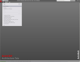
Project Browser... in the File Pulldown, Zero-Doc State
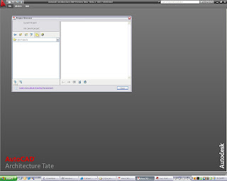
Project Browser Open, Zero-Doc State
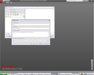
Adding a New Project, Zero-Doc State
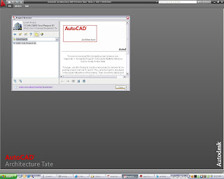
New Project Set Current, Zero Doc State
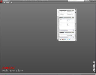
Project Navigator Open, Zero-Doc State

Here is another oft-wished for feature. There is now a button at the bottom of the Project tab of Project Navigator that will allow you to close the current project. Opening Project Browser is no longer necessary to close the current project. You will, however, need to use Project Browser to set a project current, as Project Navigator will close when the current project is closed.
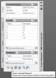
Close Current Project in Project Navigator

When closing or switching projects in 2009, you now have the option to close all project files from the project being closed.
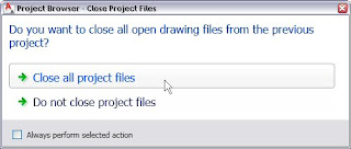
Close All Open Drawings in Closing Project

That might put you back in a zero-doc state, but that is not a problem in the 2009 release.

Yet another item is removed from the wish list: you can now open a file "read-only" from Project Navigator.
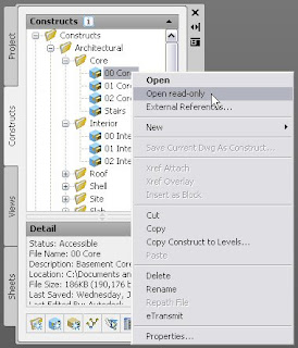
Open File Read-Only in Project Navigator

There are a number of other file-related enhancements in Project Navigator. Files that are open are now indicated graphically by the addition of a small lock in the lower right corner of the file icon. In the image below, the 00 Core, Stairs and 01 Interior Constructs are open, and show the lock icon. If you have multiple files from a project open, you are now given the opportunity to bring a particular file that is not current to the front on the right-click context menu in Project Navigator. You can also close an open file from that same context menu.
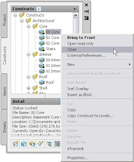
Right-click Menu Options for a Construct in Project Navigator

The External References Worksheet, accessed from that same right-click menu, has been enhanced in 2009. Instead of merely showing a list of the externally referenced files in a given Project Navigator file, you can now also see the saved path and found location for each of the external references.

External References Worksheet

The Project Properties Worksheet has gotten a makeover, making it easier to find the particular item you want to edit. Of particular interest, note that the last item, Project Tool Palette Group, is set to None. Project Tool Palettes are now optional.
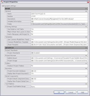
Project Properties Worksheet

Drawing tooltips in Project Navigator are now available, paralleling those available in the Sheet Set Manager in AutoCAD®. In Project Navigator, the tooltips are available for all files types, not just Sheets.
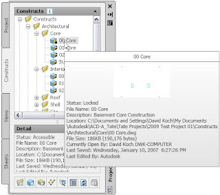
Drawing Tooltips in Project Navigator

The tooltips combine the information on the Detail and Preview options of the Detail area at the bottom of Project Navigator; you may find that you can close the Detail area, expanding the file viewing area, and using the tooltip when you need to see that information.

There are a number of other Drawing Management enhancements. If these sound like a solution to one or more pain points for you, be sure to check them out in 2009:
  • Double-click on APJ file enhancements.
  • Commas in Sheet file names (and therefore sheet drawing titles).
  • Who-has information
  • Recovery from failed, cancelled or missed repathing.
  • Reference file repathing queue worksheet.
  • Use layout name for sheet name.
  • Improvements to the Attach Elements to Constructs Worksheet
  • Project Templates installation location improvements.

Additional Features
The context menu for external references has been improved, with the addition of several new options. You can now unload, reload, detatch or bind an external reference from the context menu.
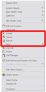
External Reference Right-Click Context Menu

Support for gbXML has been added to the 2009 release. Those of you interested in green building and extracting information from the building model will want to look into this more deeply. You can find an overview at the gbXML.org website.

IFC import and export has been improved to provide greater control over the IFC process.

Material tools now allow you to apply a material directly to a component of an AEC object or to an AutoCAD object. When a tool is active, hovering over a component will highlight the component and give you a tooltip identifying the component and listing the material that would be applied. The tooltip will also let you know if the highlighted component can not accept a material. For AEC objects with styles, the assignment can be made at the style or object level.
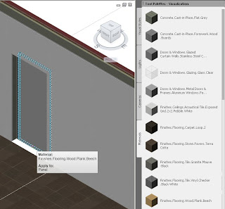
Applying a Material to a Door Panel with a Material Tool

Here is another one that many have asked for over the years - all dialogs in ACD-A 2009 are resizable. I have not personally opened every single one to see if this is true, but I do not recall any that could not be resized.

The Match Properties command (MATCHPROP) now also allows you to copy the style of an AEC object to other objects of that type. Look for the new icon on the Standard toolbar.
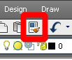
Match Properties Icon

The Display tab of the Properties palette has also been improved. The "light bulb" icons on the components list that formerly only indicated whether or not the component was on or off can now be used to toggle the on/off status of the component.
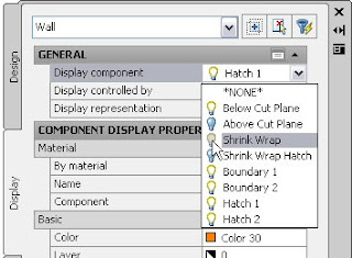
Toggle Component Visibility with Light Bulb Icon

All of the Display Properties of an object, including properties that appear on additional tabs like Cut Plane and Other in the Display Manager, are now available through the Display tab of the Properties palette.
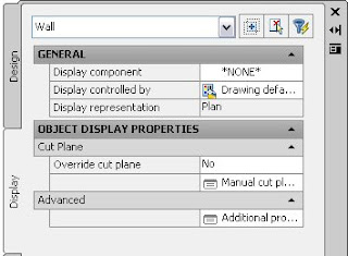
All Display Properties Accessible Through Display Tab


AutoCAD Features
There are also a number of improvements to AutoCAD 2009 that will also be available in ACD-A 2009. Many of these have been covered in detail by other bloggers of greater stature than I, and I will defer to their postings. If you have not already read these articles, you may want to take advantage of the following links.

General Overview
Heidi Hewett

Quick Access Toolbar
Lynn Allen
Heidi Hewett

Steering Wheel
Lynn Allen

ViewCube
Lynn Allen
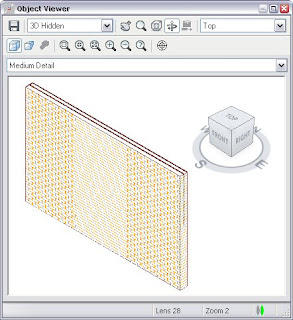
ACD-A 2009 users will also see the ViewCube in the Object Viewer.and the Components tab of a Wall Style, among other places.
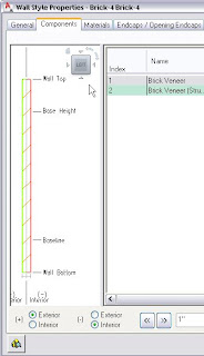
Action Recorder
Lynn Allen
Heidi Hewett

Show Motion
Lynn Allen

Quick Properties
Lynn Allen
Heidi Hewett

Quick View Layouts
Lynn Allen
Heidi Hewett
Shaan Hurley

Status Bar
Heidi Hewett

Menu Browser
Heidi Hewett

I hope this series on the new features in AutoCAD® Architecture 2009 has helped whet your appetite for the coming release and shown that there are features in the new release that make the effort to install it worthwhile.

March 02, 2008

AutoCAD Architecture 2009 - Part 3

First Article in the Series: AutoCAD Architecture 2009 - Part 1
Previous Article in the Series: AutoCAD Architecture 2009 - Part 2

Spaces
There have been several improvements to the Space object. Curved surfaces of freeform spaces are now displayed as one surface, rather than as a series of segments, as they were in previous releases. The freeform spaces shown below are from 2008, on the left, and 2009, on the right.
AutoCAD® linework, such as lines, circles and polylines, now have a "Bound spaces" property, in the Advanced category.When this is set to "yes" and you are calculating Space areas from a standard, the AutoCAD linework will affect the calculation the same way as an AEC Object that is set to bound spaces. For the BOMA standard, Base and Net areas will exclude the area of bound items within the Base and Net boundaries, respectively, while Usable and Gross areas will include the area of bound items. For AutoCAD linework, it appears that the linework needs to be entirely within the Base Area boundary, while AEC Objects can straddle a Space edge and still have their area included in the Usable and Gross area. In previous versions, when AutoCAD linework formed the boundary of a Space, the Space would still be associative to it, but the area within the AutoCAD linework would not be included in any of the areas.

The associative interaction of Spaces with objects in external references is improved. In a test file, I found that reloading the external reference with changes to the walls forming the boundaries of a space would automatically update the Spaces in the host file in 2009; a manual updating of the Space geometry was necessary in 2008.

Multi-line Attribute Text in Schedule Tags
One of the cool things added in the 2008 release was the ability to set a width for an attribute in a block, and have the entered text wrap to multiple lines if it exceeded that width. Unfortunately, that ability was not supported in Multi-View Blocks, and therefore, not in Schedule Tags. The 2009 release extends that functionality to Multi-View Blocks and Schedule Tags. One common use for this will be in room tags. You will no longer need to have multiple attributes in your view block, one for each line to be supported, and either separate Manual properties for entering the lines, with a Formula property to knit them together for use in a Schedule Table, or a set of fancy Formula properties to take the value entered into a single Manual property and chop it up into smaller pieces for use in the tag. It will also make it much easier to use List Definitions for room names.

When selecting a Schedule Tag, you will now see two or three grips. The square cyan grip is the old, familiar location grip, used to move the entire tag. If the Schedule Tag is annotative, and more than one scale is assigned to the tag, then there will be a square, yellow grip for relocating the tag graphics for the current drawing scale. New to 2009, there is now a round, gray grip that is the trigger grip for editing attributes.Selecting the edit attributes grip will enable a number of grips that allow you to edit the attributes, as shown in the composite image below. (Click on any image for a full-size version, then use the Back button to return here.)As the tooltips indicate, the two triangular cyan grips allow you to set the width of the attribute (and the tool tip lets you know the current width - 0 will display the entire text on one line). The upper circular gray grip triggers another set of grips (not shown) where you can change the justification of the attribute. The square cyan grip allows you to change the location of the attribute and the diamond cyan grip allows you to change the rotation of the attribute. The lower circular gray grip allows you to exit the attribute edit mode.

After using the left width grip (either will do) to offset the width by 3'-6", the attribute will have a total width of 7'-0"...... and result in a three-line display for the featured room tag.So easy, even a project manager could do it.

Additional Annotation Improvements
You can now associate a Display Configuration with a particular scale. Changing to that scale will also set the associated Display Configuration current. These settings are on a drawing-by-drawing basis, starting with whatever may be set in the template file, so you could have different assignments for different drawing types. For example, the imperial default setting of Medium Detail for scales from 1/8" = 1'-0" through 3/8" = 1'-0" may be appropriate for a regular plan drawing, but you will want to reset the assigned Display Configurations for a reflected ceiling plan drawing, unless you are working in a single scale. Set or change the Display Configuration assigned to a particular scale on the Scale tab of the Drawing Setup dialog.
Multi-leaders are now supported for the leader and keynoting tools.
There are new tool types for inserting various types of annotation. (Out-of-the-box DesignCenter content for imperial and metric annotation is down to Chases and Elevation labels.) These include various symbols (Bar Scale, Datum Point and North Arrow, although you could customize an instance of this tool type to insert any symbol),various polyline symbol tools (fire-resistance-rating lines - line only - and match lines and revision clouds - line and symbol)and a Column Grid Bubble tool..
The Stock Catalog's Command Tool now also features the ability to specify a Layer Key or Layer Key Overrides! This tool type is now used to provide Dimension tools and a Shrink Wrap tool that are not dependent on AEC Content.
I hope to wrap up this overview of the new features in the 2009 release in the next installment.

Next Article in the Series: AutoCAD Architecture 2009 - Part 4

February 24, 2008

AutoCAD Architecture 2009 - Part 2

First Article in the Series: AutoCAD Architecture 2009 - Part 1

Here is a quick look at the improved edit-in-place feature for wall endcaps. I must confess that my attempts at using edit-in-place for creating endcaps in previous versions were somewhat half-hearted, as I had become reasonably proficient at creating them by drawing polylines, and the "calculate automatically" feature made creating endcaps from polylines almost painless, for wall styles without stacked components. Perhaps if I had applied myself to the task more diligently, I could have mastered edit-in-place in previous versions, but my few forays generally met with disaster, and I never had time to work out what I was doing incorrectly.

So I approached this feature with low expectations in the 2009 beta, and ended up being very pleased. As previously, I dove in without first trying to read up on the process in the Help - the only "training" was a very short video that was posted, showing the feature in action. I think most people will find the improved feature much more intuitive.

The out-of-the-box CMU-8 Rigid-1.5 Air-2 Brick-4 Furring comes with an endcap style that turns the brick component back into the wall, butting into the rigid insulation, as shown below.

I created a new wall style, based on the CMU-8 Rigid-1.5 Air-2 Brick-4 Furring style, called CMU-12 Rigid-1.5 Air-2 Brick-4 Furring. As you might guess, the only difference is that the CMU component is 1'-0" wide, rather than 8" wide. This will cause the CMU-8 Rigid-1.5 Air-2 Brick-4 Furring (End 1) endcap to do strange things, as it scales things to suit the increased width of the CMU. I could have tried to edit that endcap in place, but chose instead to change the endcap to "Standard" to show just how easy it is to build a similar endcap for the CMU-12 Rigid-1.5 Air-2 Brick-4 Furring wall style "from scratch."

Selecting the wall and right clicking brings up the context menu for walls. Choosing Endcaps > Edit in Place starts the WallEndcapEdit command, and results in a prompt to select a point near the endcap.

After selecting a point near the top end of my wall instance, the GWB component's endcap was hightlighted, so I chose to start with that component. Vertices are represented by round, magenta grips; edges by rectangular ("hyphen-shaped") grips. Hovering over the edge grip at the top of the GWB component yields a tooltip that indicates the options available for that grip. For our endcap, the default Offset option will do what we need.Selecting the grip and offsetting it vertically by four inches gives us the endcap profile we need for this component.This same technique was applied to the Stud, CMU and rigid insulation components. Simply select a component to activate its endcap grips.

The Air Space component does not require an offset, as the Brick component will wrap across the top of it. The creation of the Brick component is a two-step process. The first step involves offsetting the component the same four inches vertically the same way as the other offset components were done.The second step involves using the edge grip on the right side of the now extended Brick Component, and offsetting that edge by two inches, to bring it to the face of the rigid insulation. Note that you can use object snaps when offsetting components - the edge grips will only offset perpendicular to the face, so you can snap to the endpoint of another component, even if it does not line up with the edge grip in the perpendicular direction.

At this point, having performed a total of six edge grip edits, our endcap is built. Select the save all changes button on the In-Place Edit toolbar to save the changes.The Wall Endcap Style dialog will appear, prompting you for a name for your new endcap, and offering the option of making this new endcap the wall style default, or an override for this one location. Since I was building a new endcap for this modified wall style, I chose to make this the default endcap for the wall style.

The CMU-12 Rigid-1.5 Air-2 Brick-4 Furring wall instance now sports the new wall endcap style, and the brick returns to the rigid insulation, just like its out-of-the-box cousin.

In addition to the grip edit features shown here, the right click context menu available during endcap edit-in-place allows you to add and remove vertices, hide and show edges (hide is the equivalent of drawing a polyline segment with a width, that edge will not be visible in the endcap), replace or remove the endcap, save all changes, save as a new endcap style or discard all changes. The AEC Modify tools are also available to aid in creating more complex profiles. Whether you create a lot of custom endcaps or have met with such frustration with endcaps in the past that you avoid them entirely, the improved edit-in-place of wall endcaps in the 2009 release is a feature you will want to investigate, learn and make use of in the future.

Next Article in the Series: AutoCAD Architecture 2009 - Part 3